

Toa N-CC2360, N-VT2010, N-VR2010, C-CV14-CS, N-DR2000 Installation Manual
...
INSTALLATION GUIDE
About this installation guide
This guide describes the methods of connection, software installation, setting and operation,
which are necessary for assembling and operating basic network camera systems. For more
details, please refer to the instruction or setting manuals for each device used in the system.
NETWORK CAMERA SYSTEM
TABLE OF CONTENTS
1. GENERAL DESCRIPTION ........................ 2
2. NETWORK CAMERA SYSTEM
MANUAL COMPOSITION .................... 2
3. BEFORE ASSEMBLING
THE NETWORK CAMERA SYSTEM ........ 2
4. SYSTEM CONSTRUCTION
4.1. Before Making Connections ................ 3
4.2. Basic Connection Examples ................ 3
5. MAKING CONNECTIONS
5.1. Network Video Transmitter
Connection Example ............................ 4
5.2. Network Color Camera
Connection Example ........................... 4
5.3. Network Combination Dome Camera
Connection Example ........................... 5
5.4. Network Video Recorder
Connection Example ........................... 5
5.5. Network Video Receiver
Connection Example............................ 5
6. INSTALLING THE
SOFTWARE DECODER ............................ 6
7. UNINSTALLING THE
SOFTWARE DECODER ............................ 7
8. OPERATION PROCEDURES .................... 8
9. STARTING THE SOFTWARE DECODER 9
10. EXITING THE SOFTWARE DECODER .. 10
11. CHANGING THE PC IP ADDRESS ......... 10
12. NOMENCLATURE AND FUNCTIONS .... 11
13. CREATING DEVICE LIST
13.1. Registering Devices in the
Device List by Scanning .................. 12
13.2. Registering Devices in the
Device List Manually......................... 13
14. DISPLAYING LIVE IMAGES
ON THE SOFTWARE DECODER
INSTALLED ON A PC ............................. 14
15. DISPLAYING LIVE
IMAGES VIA A RECEIVER ..................... 14
16. NORMAL RECORDING SETTINGS ........ 16
17. VIDEO RECORDING PLAYBACK
17.1. Video Recording Playback .............. 19
18. NETWORK VERIFICATION .................... 20
Thank you for purchasing TOA's Network Camera System. Please carefully follow the instructions in this
manual to ensure long, trouble-free use of your equipment.
2
1. GENERAL DESCRIPTION
The Network camera system installation guide describes the methods of connection, software installation,
setting and operation, which are necessary for assembling and operating basic network camera systems.
2. NETWORK CAMERA SYSTEM MANUAL COMPOSITION
1. Network Camera System Installation guide (This book you are reading now)
2. Network Color Camera N-CC2360 Instruction manual(Enclosed with the N-CC2360)
3. Network Combination Dome Camera N-CC2564 Instruction manual (Enclosed with the N-CC2564)
4. Network Video Transmitter N-VT2010 Instruction manual (Enclosed with the N-VT2010)
5. Network Video Receiver N-VR2010 Instruction manual (Enclosed with the N-VR2010)
6. Network Video Recorder N-DR2000 Instruction manual (Enclosed with the N-DR2000)
7. Network Camera System Setting manual (Included in the CD-ROM in PDF
format)
8. Software Decoder N-SD2000 Instruction manual (Included in the CD-ROM in PDF
format)
The above 8 manuals are available for the network camera system.
1: Explains basic system connections and installations.
2 – 6: Instruction manuals for each device.
7: Explains connection of each device, as well as device settings and camera menu settings using the Web
browser.
8: Instruction manual for the software decoder.
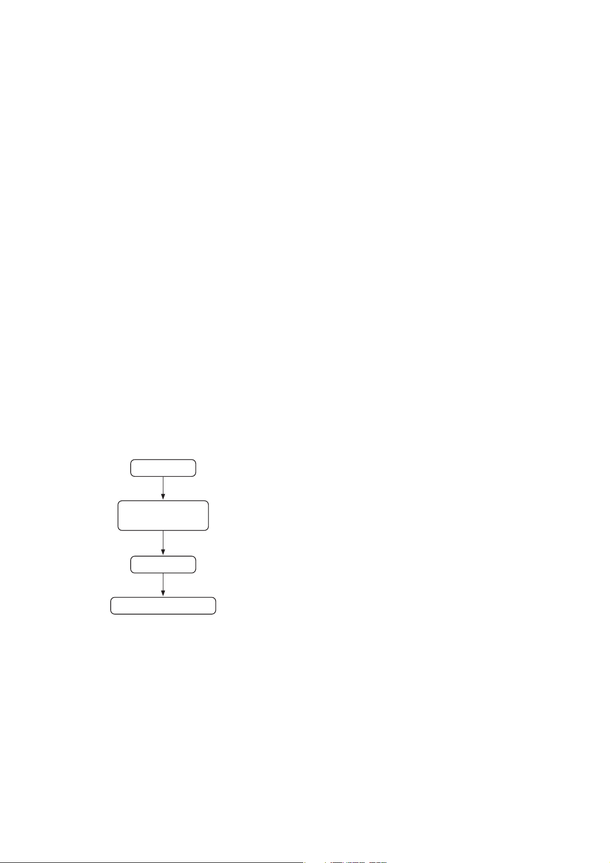
3. BEFORE ASSEMBLING THE NETWORK CAMERA SYSTEM
Use the following procedures when assembling the network camera system:
1. Make connections
Basic connections: Network camera system installation
guide
Other connections: Setting manual
2. Install the software decoder
Basic installation: Network camera system installation
guide
Detailed installations: Software decoder instruction manual
3. Perform initial settings
Basic initial settings: Network camera system installation
guide
Detailed initial settings: Setting manual, Software decoder
instruction manual and Network Video
recorder instruction manual
4. Confirm operation
Basic operations: Network camera system installation
guide
Detailed operations: Setting manual, Software decoder
instruction manual and Network video
recorder instruction manual
Basic Installation Procedure
Connection
Software decoder
Installation
Initial setting
Operation confirmation
3
4. SYSTEM CONSTRUCTION
Basic connection examples are shown for use when creating a Network camera system. Refer to the Setting
Manual (PDF file) for representative connection examples.
4.1. Before Making Connections
4.1.1. About the PoE* switching hub
Because the N-VT2010 Network Video Transmitter, N-VR2010 Network Video Receiver, and N-CC2360
Network Color Camera are compatible with PoE Standards, power can be supplied to them using a single
network cable. This eliminates the necessity for preparing a separate power supply in each camera installation
location, and greatly improves installation freedom. (*PoE : Acronym for Power over Ethernet. This complies
with the IEEE802.3af standard and allows simultaneous transmission of both normal data and DC power
using a 10BASE-T or 100BASE-TX network.)
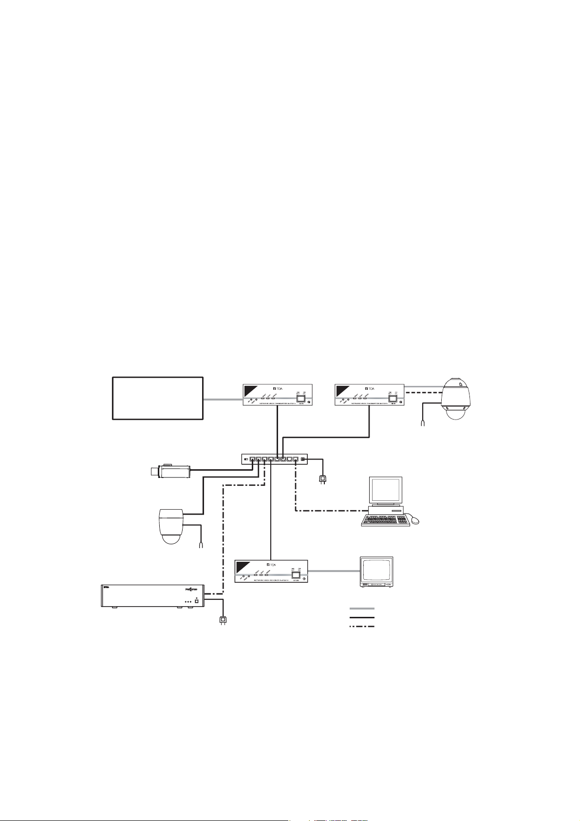
4.2. Basic Connection Examples
The connection of a basic system is shown below.
The analog CCTV system is comprised of conventional cameras and switchers.
When using a PoE-compatible hub, the power supply need not be connected to the N-VT2010 Network Video
Transmitter, N-VR2010 Network Video Receiver and N-CC2360 Network Color Camera.
When using a hub not supporting PoE, power must be independently supplied to each device. Connect AC
MAINS to N-DR2000 Network Video Recorder.
Connect 24V AC to the N-CC2564 Network Combination Dome Camera.
H
D
D
DEO
NETWORK
V
I
E
R
R
O
R
N-
RECORDER
P
O
W
E
R
DR2000
Analog
CCTV system
Network Color Camera
N-CC2360
Network Combination
Dome Camera
N-CC2564
Network Video Recorder
N-DR2000
To 24 V AC
TM
To AC mains
Network
Video Transmitter
N-VT2010
PoE compatible
switching hub
Network Video Receiver
N-VR2010
DC-IN
12345678
To AC mains
Network
Video Transmitter
N-VT2010
Software Decoder
N-SD2000
Monitor
: Coaxial cable
: 10BASE-T/100BASE-TX
: 100BASE-TX/1000BASE-T
RS-485
To 24 V AC
Combination
Dome Camera
4
-
O
CONTACT
Notes
• For more details about connection terminals, refer to the installation manual for the Combination dome
camera.
• The method used to connect the N-VT2010's front panel to the PoE-compatible switching hub is the same as
the method used for connecting the CV series camera.
5. MAKING CONNECTIONS
Refer to the following connection examples in addition to the basic system example when making connections
between devices. For more details, refer to the instruction manual for each device.
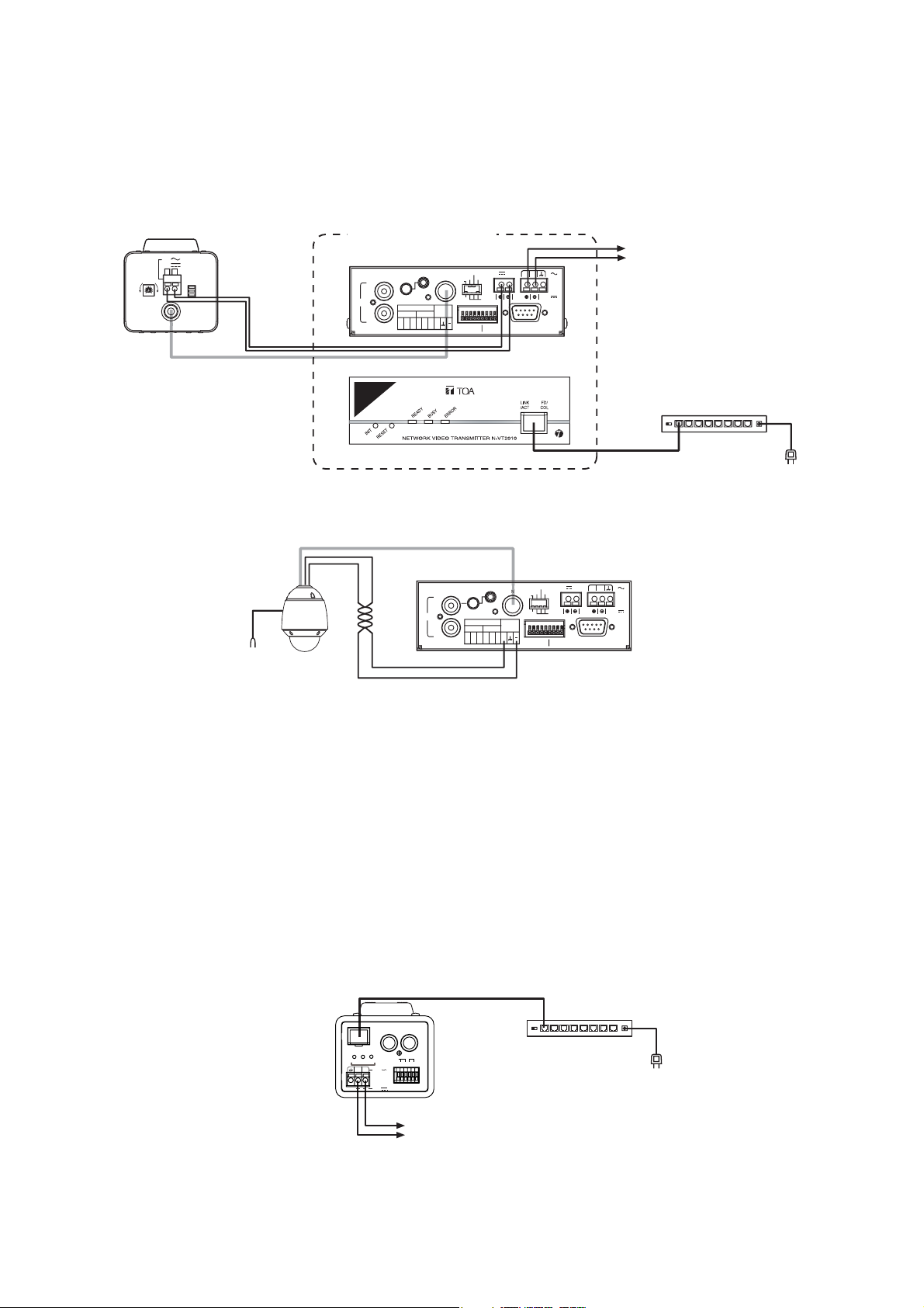
5.1. Network Video Transmitter Connection Example
5.1.1. Connection with the CV series camera
5.1.2. Connection with the combination dome camera
5.2. Network Color Camera Connection Example
[ About point view and zoom view functions ]
Point view and zoom view functions are available for the type B protocol compatible combination dome
cameras. Perform settings as follow.
• Set the camera control system to type B using the DIP switch.
(Set DIP DW2 switch No. 6 to the ON position.)
• Perform the electronic zoom setting to X2Cont, X4Cont, X8Cont, or X12Cont. Perform camera menu
operation with the software decoder via a network.
For details, refer to the N-SD2000 instruction manual and Combination dome camera setting manual.
C-CV14-CS
24V
12V
++-
IRIS
H
L
VIDEO OUT
12V DC power supply
OFF ON
FOUCUS ADJ
BLC
SHUTTER
for the CV camera
(Maximum: 0.2 A)
Video Output
Coaxial cable
Video output
Combination
Dome Camera
To 24 V AC
Network Video Transmitter
N-VT2010
Rear
AUDIO
LINE
VOL
IN
OUT
IN
12
Front
Coaxial cable
CONTACTCONTACT
C
MIC IN
12
Connect the 24 VAC or 24 VDC
AUDIO ADJ.
VIDEO
RS485
OUT
+
C
12V OUT
2
75Ω
PHANTOM
IN
MIC
LINE
CONTACT
1
24V
ON
MAX 02A
RS485
IN
RS-232C
VIDEO IN
LINK
10/100M PoE
AUDIO ADJ.
AUDIO
VIDEO
MIC IN
LINE
VOL
IN
CONTACT
OUT
RS-485
RS485
IN
OUT
+
12
12
C
C
(+)
IN
PHANTOM
MIC
LINE
CONTACT
RS-485
75Ω
ON
(
RS485
-
12V OUT
RS-232C
)
power when not using a PoE
compatible switching hub.
PoE compatible switching hub
10BASE-T/
100BASE-TX
2
1
24V
IN
Network
Video Transmitter
N-VT2010
DC-IN
12345678
To AC mains
LINK
10/100M
Network Color Camera
N-CC2360
FD/
COL
RDY
BUSY ERR
2 1
?
?
MONITOR
AUDIO
OUT
LINK/
ACT
IN
12C 12C
24V
CONTACT
24V
10BASE-T/
100BASE-TX
OUT
OUT
Connect the 24 VAC or 24 VDC power
when not using a PoE compatible switching hub.
PoE compatible switching hub
DC-IN
12345678
To AC mains
5
CONTACT
5
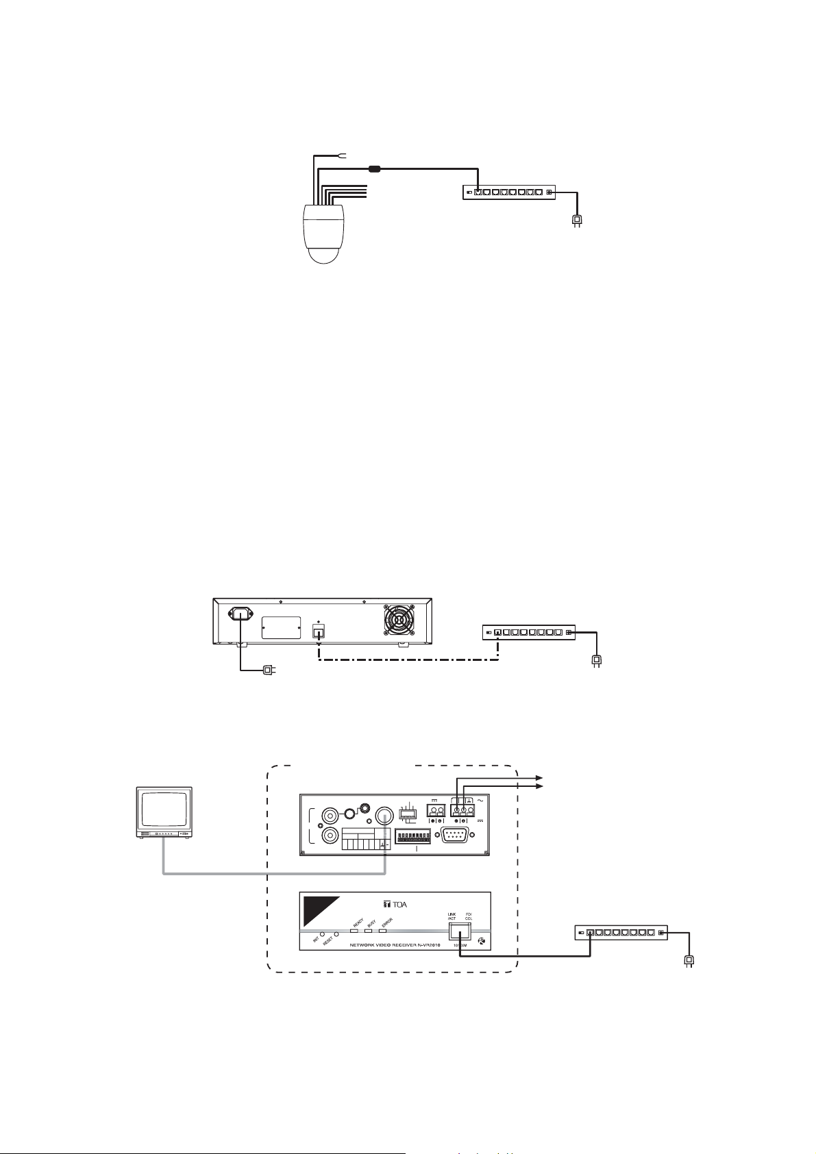
5.3. Network Combination Dome Camera Connection Example
Note
Because the power to the network combination dome camera is supplied from the existing AC line power
source, the PoE switching hub need not be used.
Note
For more details about connection terminals, refer to the instruction manual for the network combination
dome camera.
5.4. Network Video Recorder Connection Example
Note
Because the power to the network video recorder is supplied from the existing AC line power source, the PoE
switching hub need not be used.
5.5. Network Video Receiver Connection Example
[ About point view and zoom view functions ]
Point view and zoom view functions of the software decoder are available for the network combination dome
cameras. Perform settings as follow.
• Perform the electronic zoom setting to X2Cont, X4Cont, X8Cont, or X12Cont. Perform camera menu
operation with the software decoder via a network.
For details, refer to the N-SD2000 instruction manual and network camera system setting manual.
To 24 V AC
LAN terminal
Network
Combination
Dome Camera
N-CC2564
Switching hub
To AC mains
DC-IN
12345678
Network Video Recorder
N-DR2000
Switching hub
DC-IN
12345678
To AC mains
LINK
100BASE-TX/
1000BASE-T
To AC mains
Monitor
VIDEO IN
Coaxial cable
Network Video Receiver
N-VR2010
Rear
AUDIO
LINE
IN
OUT
Front
AUDIO ADJ.
VIDEO
MIC IN
VOL
OUT
CONTACT
RS485
IN
OUT
+
12
12
C
C
12V OUT
2
75Ω
PHANTOM
MIC
LINE
8
CONTACT
1
24V
ON
RS485
IN
RS-232C
VIDEO OUT
LINK
Connect the 24 VAC or 24 VDC
power when not using a PoE
compatible switching hub.
PoE switching hub
10BASE-T/
100BASE-TX
To AC mains
DC-IN
12345678
Note: The 12 V DC terminal can be used to supply power to the remote controller, etc. (Maximum: 0.2 A)
6
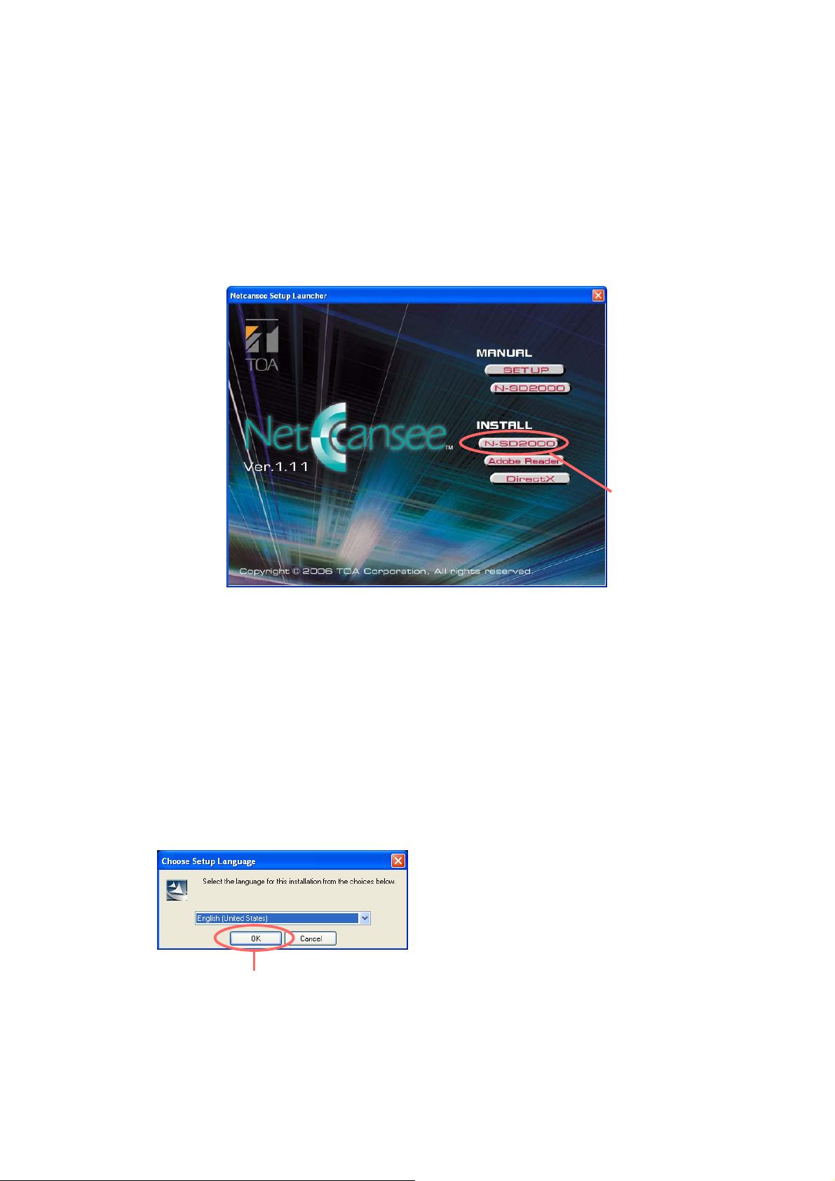
Click on “OK.”
Click on “N-SD2000.”
A “Setup language selection” dialog is displayed.
Click on √ to select “English,” then click on “OK.”
[Manual]
SETUP : Opens the Setting Manual.
N-SD2000 : Opens the Software Decoder Instruction Manual.
[Installation]
N-SD2000 : Begins to install the N-SD2000 software.
Adobe Reader : Begins installation of Adobe Reader.
DirectX : Begins installation of DirectX.
6. INSTALLING THE SOFTWARE DECODER
Install the N-SD2000 software decoder on a PC.
1. Insert the CD-ROM into the PC’s optical drive. When the PC recognizes the CD-ROM, the “Netcansee
Setup Launcher” is automatically started.
Note
If the CD-ROM drive is not compatible with AutoRun, the Setup Launcher will not start when the CD-ROM is
inserted. If this happens, simply click on “Autorun.exe” in the CD-ROM to start the Netcansee Setup Launcher.
2. Click on “N-SD2000.”
 Loading...