

Page 1
INSTALLATION MANUAL
IP DOOR STATION BOARD N-8640SB
Be sure to ground the operation panel.
CAUTION
Use the specied AC adapter in combination.
Failure to do so may cause a re.
1. GENERAL DESCRIPTION
The N-8640SB is an IP door station assembly kit consisting
of Main and Sub PC boards, cables, and mounting hardware
(excluding the operation panel) of the N-8640DS IP door station.
You can make the IP door station suitable for applications using
this kit in combination with the operation panel section to be
prepared separately.
Use the N-8000 Setting Software* to perform settings. Set up the
same items as those for the N-8640DS since the N-8640SB is
handled as the N-8640DS on the software.
Settings and operations are the same as those of the N-8640DS.
For details, read the descriptions about the N-8640DS in the
N-8000 series instruction manual*.
* Available for download on the TOA product data download site
(http://www.toa-products.com/international/).
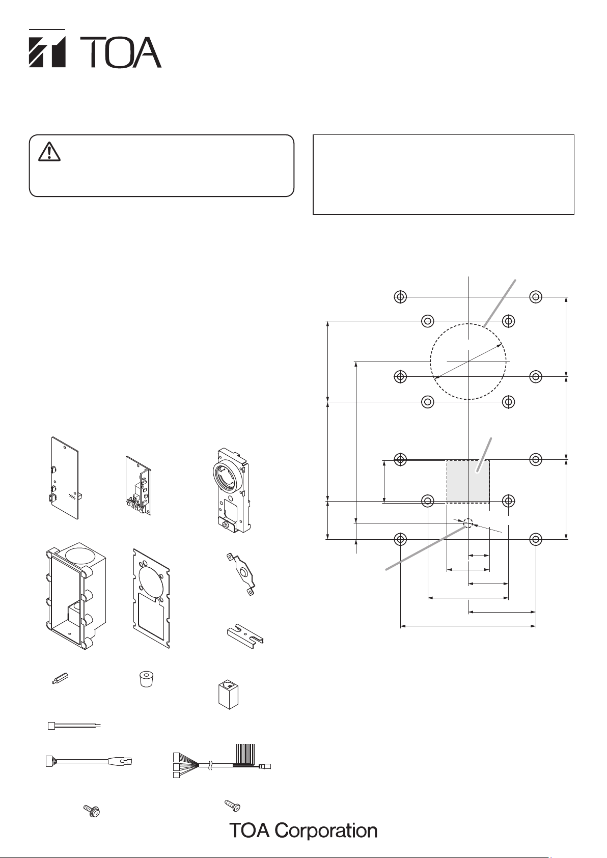
2. COMPONENT PARTS
Main PC board ... 1
Sub PC board … 1
Chassis (with speaker
and microphone) … 1
Follow the instructions below.
Doing otherwise may cause unit failure.
• The operation panel should be metallic.
• Install a frame ground terminal and ground the operation
panel. For details, refer to p. 4, "5. CONNECTIONS".
3. OPERATION PANEL DESIGN GUIDELINE
The operation panel should be metallic, and grounded.
Note:
[Chassis and case mounting sleeve layout]
Speaker mounting position
4049
80
A
B B
φ37.5
Speaker diameter
A A
B B
Switch position range
A A
A
41 39.5
Case … 1
Sleeve … 3
Call switch connection
harness … 1
LAN connection cable … 1
Machine screw M3 x 8
(with plain and spring washers) … 17
Case gasket … 1
Cord bush … 2
Speaker bracket … 1
Cord bush fixing bracket … 1
LAN coupler … 1
Power supply and external
input/output connection cable … 1
Tapping screw 3 x 8 … 1
21
19
8
Microphone
mounting position
B
Microphone diameter
φ4.5
A
10.5
21
20
40
67
B
39.5
A
33.5
Unit: mm
• A: Case mounting sleeve position
• B: Chassis mounting sleeve position
• Sleeve height: 11 mm (from the panel’s rear surface)
• Sleeves should be metallic.
• Speaker opening size should be roughly 30% of the area of a
circle with the speaker’s diameter.
• Microphone opening size should be roughly 70% or more of the
area of a circle with the microphone’s diameter.
[Notes on the Call switch]
• Position the Call switch within the range shown above.
• The Call switch’s height should be 20 mm or less from the operation panel’s rear surface.
• The Call switch should be of momentary type.
• When the above conditions could not be satised, provide an
external call switch using the external control input cables.
133-06-304-6C
Page 2
4. ASSEMBLING
Step 1.
Step 2.
2-1.
Note
2-2.
Place the Case gasket onto the operation panel, then
screw the chassis and speaker bracket to the operation
panel.
Connect the connection cables and harness to the
Main PC board, then secure the Main PC board to the
chassis.
Connect the speaker and microphone connection
cables (tted with a connector) from the chassis to the
Main PC board. Connect between the Call switch on
the operation panel and Main PC board using the Call
switch connection harness.
If no Call switch is installed on the operation panel,
connect the external control input cables to the external
switch. (See Example 3 on p. 4, “Connections.”)
Secure the Main PC board to the chassis using the
sleeves.
Speaker bracket
Machine screw (with plain
and spring washers) M3 x 8
1
Chassis
Step 3.
Step 4.
Connect the power supply and external input/output
connection cable to the Sub PC board.
Join the connector on the Sub PC board and that on the
Main PC board together, then screw the Sub PC board
onto the sleeves.
Machine screw (with plain and
spring washers) M3 x 8
4
Sub PC board
4
Sleeve
Chassis gasket
Power supply and
external input/output
connection cable
Viewed from the component side
3
Power supply and
external input/output
connection cable
2
-2
Main PC board
Call switch
connection harness
Cables from the chassis
Chassis
Viewed from the rear side
2
-1
Cables from the chassis
To the switch on the operation panel
Call switch
connection harness
Page 3

Step 5.
5-1.
5-2.
Run the connection cables through the case’s cable
entry holes, then make cable connections.
Run the LAN connection cable through the case’s
cable entry hole on your left, then connect it to the LAN
connector on the Main PC board.
Run the power supply and external input/output
connection cable connected to the Sub PC board in step
3 through the other cable entry hole from the inside of
the case, then pull it out.
[Dimensional diagram for the completed assembly]
79
53
69
Unit: mm
Step 6.
Step 7.
7-1.
7-2.
Screw the case to the sleeves fixed to the operation
panel.
Secure the cables to the case.
Install the cord bush to each cable.
Screw the cord bush fixing bracket to the case while
pressing both cord bushes with it.
Machine screw (with plain
and spring washers)
M3 x 8
6
134
Note
Numerical values in parentheses
are for reference only.
Cord bush
Note
7
-1
A slit is provided on each cord bush.
Install the cord bush with its slit
facing inward.
(135)
(130)
Case
LAN connection cable
LAN connector
5
-1
LAN connection
cable
Power supply and external
input/output connection cable
5
-2
Power supply and external
input/output connection cable
Cord bush fixing bracket
7
-2
Tapping screw 3 x 8
Page 4

5. CONNECTIONS
N-8640SB
Frame
ground
LAN connection
cable
Ext. connection cables
(Shown at right.)
Power cable
LAN coupler
AC adapter*
Use the AC adapter
A straight through
cable of UTP
category 5 or more
To network
Connecting the station to a PoE (Power over Ethernet)
Note:
switching hub compliant with IEEE802.3af eliminates
the need for an AC adapter.
*
AD-1210P/1215P (optional)
or the equivalent.
As for the usable adapter,
consult your TOA dealer.
To AC mains
Be sure to ground the N-8640SB's frame ground terminal.
Also ground the electrical box if used.
Ext. connection cables Specifications Connected device Reference
Control OUT 1
Control OUT 2
Control OUT 3
Control OUT 4
Control OUT COM
Control OUT
Control OUT
Control IN HOT
Control IN COM
Speaker cable
Speaker cable
Color
BRN
Open collector OUT
RED
Withstand voltage: 30 V DC
ORG
Max. control current: 50 mA
YEL
PUR
Relay contact OUT
BLU
Withstand voltage: 30 V DC
BLU
Max. control current: 500 mA
No-voltage closed contact IN
GRY
Open voltage: 5 V DC
WHT
Short-circuit current: 10 mA or less
BLK
Max. OUT 0.5 W
8Ω
BLK
[Example 1]
HOT
COM
[Example 2] (When using a 24 V DC relay)
Control OUT (BLU)
Control OUT (BLU)
[Example 3]
Control IN HOT (GRY)
Control OUT 1 (BRN)
Control OUT COM (PUR)
-
An indicator or other
external equipment
An electronic lock
or other external
equipment
A switch, sensor,
or other external
equipment
Ext. speakers
(8 Ω, 0.6 W or more)
Max. 50 mA
Diode
Relay
+
Example 1
Example 2
Example 3
Battery etc.
Max.30 V DC
Ext. power supply
24 V DC
GND
Control IN COM (WHT)
6. SPECIFICATIONS
Power Source Power supply device that complies with IEEE802.3af standard or 12 V DC (supplied from the AC adapter)
Power Consumption Use of the AC adapter (12 V DC): 3.5 W (station only), Use of the PoE (48 V DC): 5 W
Speech Method Hands-free conversation
Audio Frequency Range 300 Hz – 7 kHz
Hands-free Speaker: 3.5 cm cone-type, maximum output 0.5 W, 8 Ω
Control Input 1 channel, no-voltage make contact input, open circuit voltage: 5 V DC, short-circuit current: 10 mA or less,
Control Output Open collector output, 4 channels, withstand voltage: 30 V DC, control current: Max. 50 mA (4 output 1 COMMON),
External Speaker Output Maximum output 0.5 W, 8 Ω, unterminated ends
Network Section Network I/F:
Operating Temperature –10 to +50℃
Operating Humidity Under 90 % RH (no condensation)
Dimensions 79 (w) x 134 (h) x 53 (d) mm (Complete assembly of parts)
Weight 350 g (Total weight)
Optional Products AC adapter: AD-1210P or AD-1215P
Microphone: Omni-directional electret condenser microphone
unterminated ends
unterminated ends
Relay contact output, 1 channel, withstand voltage: 30 V DC, control current: Max. 500 mA, unterminated ends
Network Protocol:
Audio Packet Transmission System:
Number of Paging Destinations:
LAN Connector:
Voice Sampling Frequency:
Quantifying Bit Number:
Voice Encoding Method:
Voice Packet Loss Recovery:
Audio Delay Time:
10BASE-T/100BASE-TX (Automatic-Negotiation)
TCP/IP, UDP, HTTP, RTP, ARP, ICMP, IGMP
Unicast, Multicast
0 Note: Reception only
RJ-45 connector (PoE compatible)
16 kHz, 8 kHz (controllable on the software)
16-bit
Sub-band ADPCM, Cryptosystem
Silence insertion
80 ms, 320 ms (controllable on the software)
Note: The design and specifications are subject to change without notice for improvement.
URL: http://www.toa.jp/
 Loading...