

Toa N-8540DS Installation Manual
INSTALLATION
MANUAL
IP DOOR STATION N-8540DS
Designed to connect to the IP network, the N-8540DS is an
indoor use door station featuring high quality hands-free
conversation. It has a contact output (momentarily closed) to
remotely control an electronic door lock. Using with an
electrical box or surface mounting box, the station can be
mounted to a wall. The operating temperature range is
–10°C to +50°C.
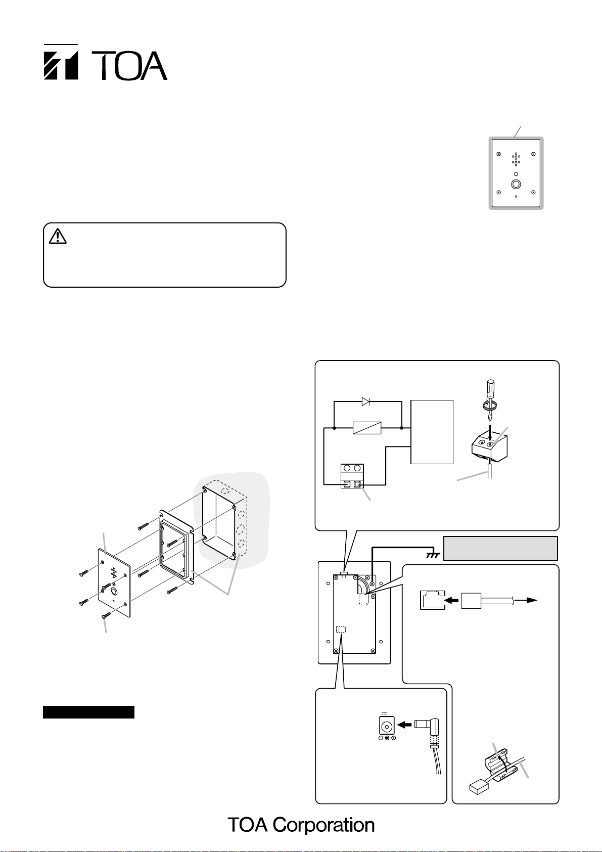
3. WALL MOUNTING
2. GENERAL DESCRIPTION
3.1. Mounting to a 3-gang Switch Box (with cover)
Mount the N-8540DS to the
electrical box mounted in
the wall.
Note
The wall should be over 12 mm thick, and the opening in the
wall for an electrical box should be under 115 mm (wide) by
162 mm (high).
3.2. Mounting to the YS-13A Wall Mount Box
Install the YS-13A on a wall and mount the station in the
same way as 3.1.
5. WIRING
[Power supply connection]
The following 2 methods are available for supplying power
to the station.
• From a DC 12 V AC adapter
• From an IEEE802.3af compliant PoE switching hub
(For connection, refer to the instruction manual supplied
with the switching hub.)
Printed in Japan
133-21-554-60
The N-8540DS comes with 2 types of screws: oval head
combination screw M4 x 25 and oval head slotted screw
UNC No.6 x 18.
For the electrical box provided with unified threads, use the
oval head slotted screws UNC No.6 x 18.
Accessory screws
• Before installation or use, be sure to carefully read all the
instructions in this section for correct and safe operation.
• Be sure to follow all the precautionary instructions in this
section, which contain important warnings and/or cautions
regarding safety.
• After reading, keep this manual handy for future reference.
1. SAFETY PRECAUTIONS
CAUTION
Indicates a potentially hazardous situation which, if
mishandled, could result in moderate or minor personal
injury, and/or property damage.
• Use the dedicated AC adapter or its equivalent for the unit.
Note that the use of other adapter may cause a fire.
4. INSTALLATION PRECAUTIONS
• When installing the N-8540DS
outdoors or at locations where it gets
wet with water, tightly seal the panel
edges. Besides, provide a weep hole
at the underside of the mounting box
to permit water to drain off.
• When installing the N-8540DS under
difficult environmental conditions
such as in coastal areas or at humid
locations, cover the inside of the N8540DS with coating. For the coating
method, consult your TOA dealer.
Seal the panel edges.
N-8540DS's
front panel
[Connection to an external relay]
Diode
Relay
-
Contact outout
terminal
+
External
power supply
+24 V DC
GND
• Connections
Tighten
Terminal screw
Wall
surface
N-8540DS
3-gang electrical box
YC-150 (optional)
Oval head combination screw
M4 x 25 (accessory)
HC
Open collector output:
30 V DC, 50 mA
Frame ground (FG)
HC
LAN
Network Connection Terminal
[Network connection]
Can be connected to a network of
10BASE-T/100BASE-TX in auto-sensing.
Use a UTP category 5 straight-through
N-8540DS
rear
[AC adapter connection]
12V 400mA
AC adapter
terminal
Connect the AC adapter*.
Use the AD-1210P (optional)
*
or equivalent.
As for the usable adapter,
consult your TOA dealer.
cable with an RJ-45 connector for this
connection.
DC INPUT
Cable
Bared end: 7 mm
Conductor diameter:
ø 0.4 – 1.3 mm (AWG16 – 20),
Solid wire/Stranded wire
Ground from the FG when the
switch box is not grounded.
LAN
LAN
Note
Install the supplied ferrite
clamp on the cable.
Ferrite clamp
(accessory)
To network
Cable
 Loading...