

Page 1
N-8000MS
N-8010MS
N-8020MS
MULTIFUNCTIONAL MASTER STATION
STANDARD MASTER STATION
INDUSTRIAL-USE MASTER STATION
INSTALLATION MANUAL
These Master Stations are designed to connect to the IP Intercom Exchange, and provide hands-free conversation of high
sound quality.
Using an optional YC-280 Wall Mounting Bracket, these stations can be mounted on a wall, or tilted for easy key operation
when used on a desktop.
Warning
This is a class A product. In a domestic environment this product may cause radio interference in which case the user may be
required to take adequate measures.
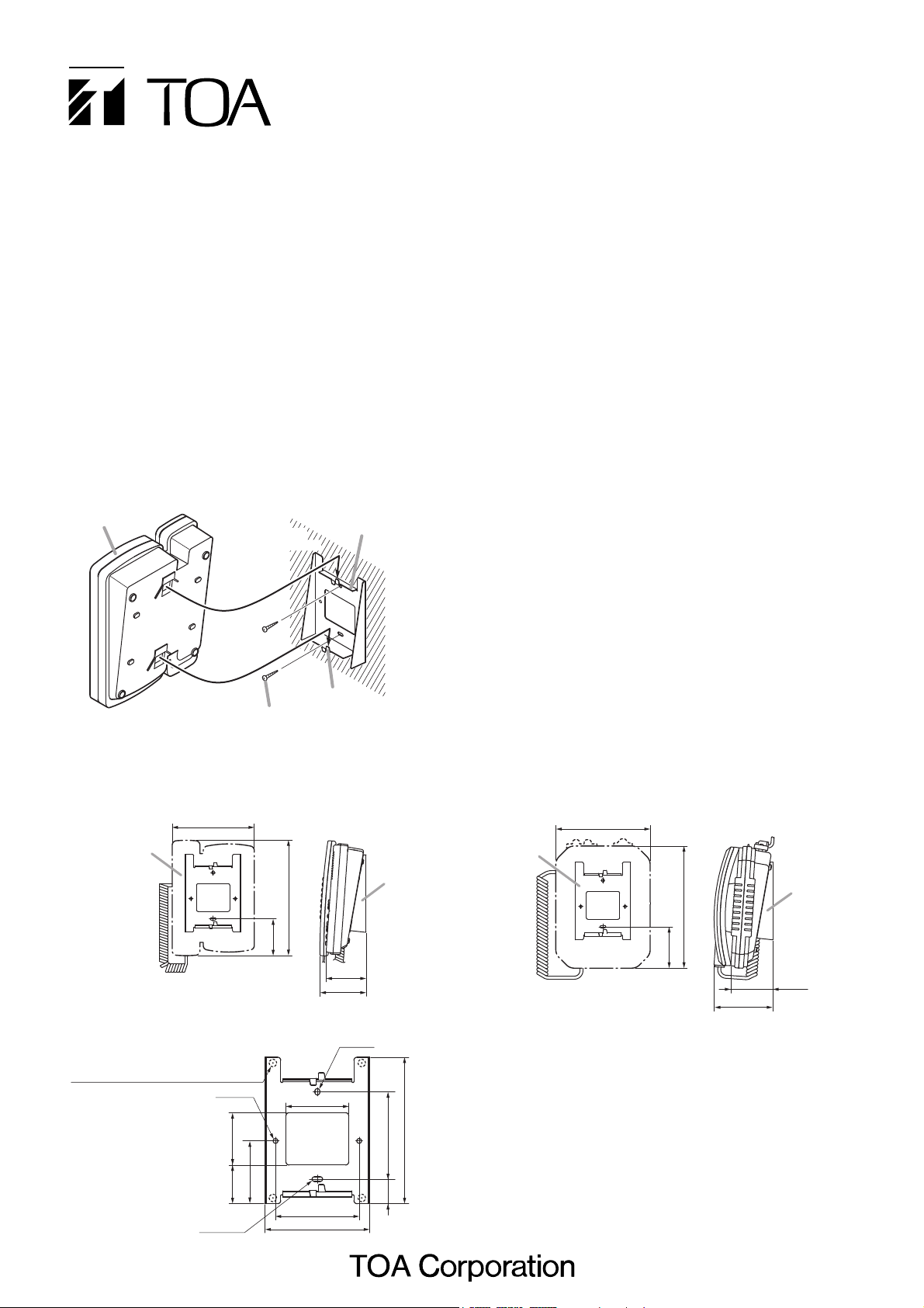
1. WALL MOUNTING
The station can be mounted on a wall using an optional YC-280 wall-mounting bracket.
The YC-280 can be installed to JIS standard one gang switch box.
1.1. Mounting Example
Step 1. Install the YC-280 wall mounting bracket to the wall.
Notes
• Use the appropriate screws for the construction of wall.
• Wooden screws 3.5 x 20 are supplied with the YC-280.
• No fitting screws for switch box are supplied with.
Use commercially available screws.
Step 2. Hang the station on the wall mounting bracket hook to
install.
Push down the station main body in the direction
indicated by the arrow.
1.2. Installation Completion Drawing
Unit: mm
1.3. YC-280 Dimensional Drawing
Unit: mm
Unit: mm
Station
2
YC-280 Wall mounting
bracket (optional)
Wall
surface
1
Note: The figure shows
the N-8000MS.
[N-8000MS/8010MS]
148
YC-280
Rubber foot mounting position
(desk-top application)
2-ø4.5
Wooden screw 3.5 x 20
(supplied with the YC-280)
208
66.2
60
Hook
72.1
83.5
4.6 x 6
YC-280
[N-8020MS]
170
YC-280
220
74.7
106.5
YC-280
76.2
5037
4.5 x 10
60
80
100
83.5
23.5
140
Page 2
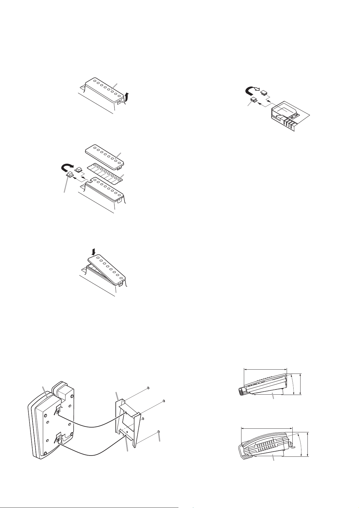
2. WALL MOUNTING
When mounting the station on a wall, the orientation of the
handset hook needs to be changed.
2.1. N-8000MS or N-8010MS Station
Step 1. Raise the number directory cover forward tab.
Step 2. Remove both the number directory cover and the
directory. Remove the handset hook and reverse its
orientation, then replace.
Step 3. After replacing the directory on the station, hook the
directory cover's forward tab and push on the upper
part of the directory cover.
2.2. N-8020MS Station
Remove the handset hook and reverse its orientation.
3. DESK-TOP INSTALLATION
In desktop installations, the front operation panel can be inclined 16˚ from the desk surface for easier operation by attaching the
YC-280 Wall Mounting Bracket to its bottom surface.
3.1. Mounting Example 3.2. Installation Completion Drawing
Hang the wall mounting bracket hook on the station's wall
bracket mounting slot to install.
Push up the Wall mounting bracket in the direction indicated
by the arrow.
Unit: mm
Number directory cover
Number directory cover
Reverse the orientation.
Number directory
Handset hook
Reverse the orientation.
Handset hook
Station
YC-280 Wall
mounting bracket
Rubber foot
(supplied with the YC-280)
Hook
Note
The figure shows the N-8000MS.
[N-8000MS/8010MS]
205.2
YC-280
[N-8020MS]
245
YC-280
16°
101.8
16°
115
Page 3

4. WIRING
4.1. Connection Diagram
(1) Station connection
To connect the cables from the N-8000EX Exchange to the
Master Station, use the connection cable* and a commercially
available RJ-11 modular jack. These cables have no polarity.
* The connection cable is supplied with the station (N-
8000MS/8010MS), while that of the N-8020MS directly
attached to the unit.
(2) Ext e r nal sp e aker t e r minal s a nd con t rol ou t p ut
terminals connections
[N-8000MS]
These terminals are designed for exclusive connection with
external speakers.
Press down the desired push-in terminal button on the rear
panel with a tip of standard driver, and insert the cable
securely.
[N-8020MS]
Follow the procedure below for external speaker terminals and
control output terminals connections.
Step 1. Remove a protection cover.
Unscrew the 3 fitting screws securing the protection
cover.
Step 2. Pull out a protection cap on the desired terminal.
Note
Do not remove the protection cover on the unused
terminal.
Step 3. Run the cable through the protection cover removed,
and then connect it to the push-in terminal.
Step 4. After inserting the cables in the supplied rubber
bushing, insert the bushing into the station, then put
the protection cover back in place.
To N-8000EX Exchange
E-7000TB
Terminal board
RJ-11 modular rosette
(commercially available)
To external speakers
Connection cable
(2)
To a device to
indicate the
calling station
Station Station
16 lines
Mini-clamp connector
(Supplied with the
N-8000EX)
Both upper and lower
terminals (clip terminals)
are internally connected.
(1)
Connection cable
(supplied with
each station)
N-8020MS rear view
Fitting screws for
the protection cover
View of the terminal where
protection cover is removed
Protection cap
Protection cover
Note
For the type of cables, refer
to p.4, The Type of Cables.
Protection cover
Protection cover fixing screw
(the screw removed in Step 1)
COM HOT
Press down the desired
push-in terminal button with
a tip of standard driver, and
insert the cable securely.
11 mm
Push-in terminal
Protection cover
Since wire leads can be pinched,
make them as short as possible.
Rubber bushing
(Supplied with the N-8020MS.)
Page 4

4.2. The Type of Cables
The types of cables are to be determined according to the
following conditions.
• Twisted pair wires (such as those used for electronic pushbutton telephone) are to be used for wiring between the
Exchange and the stations in principle.
• The number of cables pairs laid should be determined
considering the possibility of future expansion of the
system.
• Outdoor wires should be used where wiring passes through
inaccessible areas such as ceilings or under floors where
the maintenance is not performed. Indoor wires may also
be used, however, in case where there is no risk of
deterioration due to exposure to heat, etc.
Note
Specifications related to each junction are as follows.
Mini-clamp connector (N-8000EX line terminal)
Conductor diameter: ø 0.4 – 0.65 mm (AWG22 – 26),
Solid wire
Outside diameter: ø 1.05 mm or below
Clip terminal (E-7000TB)
Conductor diameter: ø 0.4 – 0.8 mm (AWG20 – 26),
Solid wire
Outside diameter: ø 1.5 mm or below
4.3. Relations Between Core Diameter of Cable and
Maximum Cable Length
Referring to the following chart as guidelines, design the
distance between the Exchange and stations so that loop
resistance value becomes 170 Ω or less.
4.4. Mini-Clamp Connector Connection
Mini-clamp connectors for line terminals are supplied with the
N-8000EX Exchange.
Connect the mini-clamp connector to a cable using a
commercially available tool (pliers).
Step 1. Cut off two-cable ends in equal length, and insert
them securely to a cover section (transparent side) of
the mini-clamp connector.
Note
Insert the cable without stripping the cable jacket.
Step 2. With a pair of pliers, lightly pinch the mini-clamp
cover and, after ensuring that the cable is securely
inserted, firmly squeeze on the cover.
Note
Squeeze on the mini-clamp cover until it is correctly
locked.
Step 3. Insert the wired connector (plug) into the exchange's
connector (socket) until it locks into place.
Conductor
diameter
(mm)
ø
0.4
ø
0.5
ø
0.65
ø
0.9
Maximum cable length between the
Exchange and station
(Assuming that the loop resistance is 170 Ω.)
570 m
900 m
1.5 km
2.9 km
Loop
resistance
(Ω/km)
295
187
113
58
133-06-262-9B
URL: http://www.toa.jp/
Cover (transparent side)
Cable
N-8000EX Rear panel
 Loading...