

Page 1

OPERATING INSTRUCTIONS
PACKET INTERCOM SYSTEM
N-8000 SERIES
Thank you for purchasing TOA's Packet Intercom system.
Please carefully follow the instructions in this manual to ensure long, trouble-free use of your equipment.
Page 2

2
TABLE OF CONTENTS
SAFETY PRECAUTIONS (For N-8000EX and N-8000MI) ................................... 10
OPERATING INSTRUCTIONS CONFIGURATION .................................................. 12
1. GENERAL DESCRIPTION ......................................................................................... 1-2
2. FEATURES ..................................................................................................................... 1-2
3. SPECIFICATIONS ........................................................................................................ 1-3
4. SYSTEM CONFIGURATION
4.1. System Configuration Example .................................................................................... 1-4
4.1.1. Exchange ........................................................................................................... 1-5
4.1.2. Peripheral components ....................................................................................... 1-5
4.1.3. Stations ............................................................................................................... 1-5
4.1.4. Others ................................................................................................................. 1-5
4.2. Component Description
4.2.1. Exchange ........................................................................................................... 1-6
4.2.2. Peripheral components ....................................................................................... 1-6
4.2.3. Stations ............................................................................................................... 1-7
4.2.4. Others ................................................................................................................. 1-7
4.3. Rack Mounting Examples for Exchanges
4.3.1. A 128-line exchange system .............................................................................. 1-8
4.3.2. A 192-line exchange system .............................................................................. 1-8
4.3.3. A 256-line exchange system .............................................................................. 1-8
4.3.4. A 1280-line exchange system ............................................................................ 1-9
5. NOMENCLATURE AND FUNCTIONS
5.1. N-8000EX IP Intercom Exchange
[Front] ......................................................................................................................... 1-10
[Rear] .......................................................................................................................... 1-10
5.2. N-8000MI Multi Interface Unit
[Front] ......................................................................................................................... 1-11
[Rear] .......................................................................................................................... 1-11
5.3. N-8000MS Multifunctional Master Station
[Top] ........................................................................................................................... 1-12
[Rear] .......................................................................................................................... 1-13
[Bottom] ...................................................................................................................... 1-14
5.4. N-8010MS Standard Master Station
[Top] ........................................................................................................................... 1-15
[Rear] .......................................................................................................................... 1-16
[Bottom] ...................................................................................................................... 1-16
5.5. N-8011MS Standard Hands-free Master Station
[Top] ........................................................................................................................... 1-17
[Rear] .......................................................................................................................... 1-18
[Bottom] ...................................................................................................................... 1-18
Chapter 1: GENERAL DESCRIPTION
Page 3

3
5.6. N-8020MS Industrial-Use Master Station
[Top] ........................................................................................................................... 1-19
[Rear] .......................................................................................................................... 1-20
[Bottom] ...................................................................................................................... 1-20
5.7. N-8031MS Flush-Mount Master Station
[Front] ......................................................................................................................... 1-21
[Rear] .......................................................................................................................... 1-21
5.8. N-8050DS Door Station
[Front] ......................................................................................................................... 1-22
[Rear] .......................................................................................................................... 1-22
6. SYSTEM FUNCTION TABLE
6.1. Basic Functions .......................................................................................................... 1-23
6.1. Multi Interface Unit's Functions .................................................................................. 1-26
7. PAGING FUNCTION OUTLINES
7.1. Paging Types
7.1.1. PA paging ......................................................................................................... 1-27
7.1.2. Station paging .................................................................................................. 1-27
7.2. Paging Functions
7.2.1. Zone paging ..................................................................................................... 1-28
7.2.2. Paging .............................................................................................................. 1-28
7.2.3. All-call paging ................................................................................................... 1-28
7.3. Station Paging Receiving Mode
7.3.1. Conversation priority mode ............................................................................... 1-28
7.3.2. Paging priority mode ......................................................................................... 1-28
7.4. Responding to Paging
7.4.1. Automatic response .......................................................................................... 1-29
7.4.2. Zone number dialing ......................................................................................... 1-29
8. MULTI INTERFACE FUNCTION OUTLINES
8.1. External Input Paging ................................................................................................. 1-30
8.2. Tie-line Connection ..................................................................................................... 1-30
8.3. PBX Interface (E and M Interface) .............................................................................. 1-30
8.4. BGM ........................................................................................................................... 1-31
8.5. Contact Input and Output Functions
8.5.1. External equipment control ............................................................................... 1-32
8.5.2. Contact bridge function (external contact interlock) ......................................... 1-32
8.5.3. Paging busy input ............................................................................................. 1-32
1. BASIC USAGE
1.1. Calling from a Master Station ....................................................................................... 2-2
1.2. Calling from a Door Station .......................................................................................... 2-3
1.3. Receiving a Call
1.3.1. Receiving a call at the master station ................................................................. 2-4
1.3.2. Receiving a call at the door station ..................................................................... 2-4
1.4. Station Speaker Volume ............................................................................................... 2-4
Chapter 2: FUNCTIONS AND OPERATION
Page 4

4
2. CONVERSATION FUNCTIONS AND THEIR OPERATION
2.1. Conversation
2.1.1. Hands-free conversation .................................................................................... 2-5
2.1.2. Handset conversation ......................................................................................... 2-5
2.1.3. PTT conversation ............................................................................................... 2-5
2.2. Calling
2.2.1. Individual calls .................................................................................................... 2-6
2.2.2. Master station calls ............................................................................................. 2-6
2.2.3. Redialing ............................................................................................................. 2-6
2.2.4. Recall .................................................................................................................. 2-7
2.2.5. Voice callings ...................................................................................................... 2-7
2.2.6. Group calls ......................................................................................................... 2-8
2.3. Setting Call Receiving Modes
2.3.1. Automatic connection ......................................................................................... 2-8
2.3.2. Continuous call ................................................................................................... 2-8
2.4. Speed Dialing
2.4.1. Auto-dialing (N-8000MS only) ............................................................................ 2-9
2.4.2. One-touch dialing ............................................................................................. 2-10
2.5. Hold
2.5.1. Mic off ............................................................................................................... 2-11
2.5.2. Call hold ............................................................................................................ 2-11
2.6. Call Transfer ............................................................................................................... 2-12
2.7. Automatic Transfer
2.7.1. Group hunting ................................................................................................... 2-14
2.7.2. Absence transfer .............................................................................................. 2-15
2.7.3. Call forwarding ................................................................................................. 2-16
2.8. Remote Response ...................................................................................................... 2-18
2.9. Executive Priority ........................................................................................................ 2-20
2.10. Time-Out ................................................................................................................... 2-20
2.11. Group Blocking ......................................................................................................... 2-21
3. PAGING FUNCTION AND OPERATION
3.1. Paging
3.1.1. Zone paging ..................................................................................................... 2-22
3.1.2. Paging .............................................................................................................. 2-23
3.1.3. All-call paging ................................................................................................... 2-24
3.2. External Input Paging (only when the N-8000MI is used) .......................................... 2-25
3.3. Responding to Paging
3.3.1. Automatic response .......................................................................................... 2-26
3.3.2. Zone number designation response ................................................................. 2-27
4. OTHER FUNCTION AND OPERATION
4.1. Scan Monitor .............................................................................................................. 2-28
4.2. PBX Connection (only when the N-8000MI is used)
4.2.1. Calling the PBX extension telephone ............................................................... 2-29
4.2.2. Being called from a PBX extension telephone ................................................. 2-29
4.3. Tie-Line Connection (only when the N-8000MI is used)
4.3.1. Calling another intercom system ...................................................................... 2-30
4.3.2. Being called from another intercom system ..................................................... 2-30
4.4. BGM (only when the N-8000MI is used) ..................................................................... 2-31
4.5. External equipment Control (only when the N-8000MI is used) ................................. 2-32
4.6. Calling Station Indication/CCTV Interlock (only when the N-8000MI is used) ............ 2-34
4.7. Door Remote Control (only when the N-8050DS or N-8000MI is used) ..................... 2-35
Page 5

5
4.8. Contact Bridge (only when the N-8000MI is used) ..................................................... 2-36
4.9. Paging Busy Input (only when the N-8000MI is used) ................................................ 2-36
5. OPERATION TABLE AT MASTER STATIONS ................................................. 2-37
6. MULTIFUNCTIONAL MASTER STATION'S LCD DISPLAY TABLE .......... 2-38
1. INSTALLATION OF THE EXCHANGE
1.1. Equipment Rack Mounting
1.1.1. Setting space ...................................................................................................... 3-2
1.1.2. Caution when installing the unit .......................................................................... 3-2
1.1.3. Exchange mounting ............................................................................................ 3-3
1.2. Desk-Top Installation .................................................................................................... 3-3
1.3. Wall Mounting ............................................................................................................... 3-4
2. INSTALLATION OF THE MULTI INTERFACE UNIT
2.1. Equipment Rack Mounting
2.1.1. Setting space ...................................................................................................... 3-5
2.1.2. Caution when installing the unit .......................................................................... 3-5
2.1.3. N-8000MI mounting ............................................................................................ 3-6
2.2. Desk-Top Installation .................................................................................................... 3-6
2.3. Wall Mounting ............................................................................................................... 3-7
3. INSTALLATION OF STATIONS
3.1. When Mounting the Station on a Wall
3.1.1. N-8000MS or N-8010MS Station ........................................................................ 3-8
3.1.2. N-8020MS Station .............................................................................................. 3-8
3.2. On-Wall Mounting
3.2.1. N-8000MS/8010MS/8020MS .............................................................................. 3-9
3.2.2. N-8011MS ........................................................................................................ 3-11
3.3. Desk-Top Installation
3.3.1. N-8000MS/8010MS/8020MS ............................................................................ 3-13
3.3.2. N-8011MS ........................................................................................................ 3-14
3.4. In-Wall Mounting Using an Electrical Box
3.4.1. N-8031MS ........................................................................................................ 3-15
3.4.2. N-8050DS ......................................................................................................... 3-16
3.5. On-Wall Mounting Using a Wall-Mount Box
3.5.1. N-8031MS ........................................................................................................ 3-17
3.5.2. N-8050DS ......................................................................................................... 3-18
4. WIRING
4.1. Exchange Connection ................................................................................................ 3-19
4.2. Station Connection
4.2.1. Station and Exchange connection .................................................................... 3-21
4.2.2. External speaker terminals and control output terminals connections ............. 3-23
4.2.3. N-8031MS and RS-191 connections ................................................................ 3-24
4.2.4. N-8031MS and external switch connections .................................................... 3-25
4.2.5. N-8050DS and external relay connections ....................................................... 3-25
4.3. Multi Interface Unit Connection .................................................................................. 3-26
4.4. Type of Cable ............................................................................................................. 3-29
Chapter 3: INSTALLATION & WIRING
Page 6

6
4.5. Relations Between Core Diameter of Cable and Maximum Cable Length ................. 3-29
4.6. Connector Connection
4.6.1. Mini-clamp connector connection ..................................................................... 3-30
4.6.2. Terminal plug connection ................................................................................. 3-30
4.7. E-7000TB Terminal Board Wiring ............................................................................... 3-32
1. SYSTEM SETTING ITEMS AND DEFAULT
1.1. General System ............................................................................................................ 4-2
1.2. Exchange
1.2.1. Network settings ................................................................................................. 4-3
1.2.2. Sampling frequency correction ........................................................................... 4-3
1.2.3. Function settings ................................................................................................ 4-4
1.3. Multi Interface Unit
1.3.1. Network settings ................................................................................................. 4-5
1.3.2. Sampling frequency correction ........................................................................... 4-5
1.3.3. Function settings ................................................................................................ 4-5
1.3.4. Audio I/O ............................................................................................................. 4-6
1.3.5. Contact I/O ......................................................................................................... 4-6
1.4. Stations
1.4.1. Function settings ................................................................................................ 4-7
1.4.2. Speed dialing ...................................................................................................... 4-7
1.4.3. Scan monitor ...................................................................................................... 4-8
1.4.4. Paging ................................................................................................................ 4-8
1.4.5. Group .................................................................................................................. 4-8
2. TURNING THE SYSTEM'S POWER SWITCH ON
2.1. Caution When Turning the Power Switch On ............................................................... 4-9
2.2. Turning the Power Switch On ....................................................................................... 4-9
3. SETTING PROCEDURES .......................................................................................... 4-9
4. NETWORK SETTINGS USING A PERSONAL COMPUTER ....................... 4-10
1. N-8000 SOFTWARE GENERAL DESCRIPTION
1.1. General Description
1.1.1. Equipment scan and network setting functions .................................................. 5-2
1.1.2. System setting function ...................................................................................... 5-2
1.2. PC Network Settings .................................................................................................... 5-2
1.3. Notes on Setting Update .............................................................................................. 5-2
2. INSTALLING SOFTWARE
2.1. System Requirements .................................................................................................. 5-3
2.2. Activating the Setup Guide ........................................................................................... 5-3
2.3. N-8000 Software Installation
2.3.1. Installation .......................................................................................................... 5-4
2.3.2. Version update information ................................................................................. 5-5
2.3.3. Install folder configuration ................................................................................... 5-6
Chapter 5: SYSTEM SETTINGS BY SOFTWARE
Chapter 4: BEFORE PERFORMING SYSTEM SETTINGS…
Page 7

7
2.4. N-8000 Software Uninstallation .................................................................................... 5-6
3. ACTIVATING N-8000 SOFTWARE PROGRAM .................................................. 5-7
4. UNIT SCAN AND NETWORK SETTINGS
4.1. Screen Description ....................................................................................................... 5-9
4.2. Menu
4.2.1. File .................................................................................................................... 5-10
4.2.2. Scan ................................................................................................................. 5-10
4.2.3. Help .................................................................................................................. 5-10
4.3. Buttons ....................................................................................................................... 5-10
4.4. Using Unit Scan .......................................................................................................... 5-11
4.5. Changing Equipment Settings .................................................................................... 5-12
4.6. Automatic IP Address Assignment ............................................................................. 5-12
4.7. Subnet Mask and Default Gateway Settings .............................................................. 5-13
5. SYSTEM SETTING FUNCTION
5.1. Screen Description ..................................................................................................... 5-15
5.2. Menu
5.2.1. File .................................................................................................................... 5-16
5.2.2. Setting .............................................................................................................. 5-16
5.2.3. Help .................................................................................................................. 5-16
5.3. Overall System Configuration Settings
5.3.1. Equipment registration ...................................................................................... 5-17
5.3.2. Station number and type settings ..................................................................... 5-19
5.3.3. Network communications registration ............................................................... 5-20
5.3.4. Multicast communications registration .............................................................. 5-21
5.4. Exchange Settings
5.4.1. Network settings ............................................................................................... 5-22
5.4.2. Sampling frequency correction settings ............................................................ 5-25
5.4.3. Function settings .............................................................................................. 5-26
5.5. Multi Interface Unit Settings
5.5.1. Network settings ............................................................................................... 5-28
5.5.2. Sampling frequency correction settings ............................................................ 5-31
5.5.3. Function settings .............................................................................................. 5-32
5.5.4. Audio I/O settings ............................................................................................. 5-34
5.5.5. Contact setting .................................................................................................. 5-36
5.6. Setting Stations Connected to the Exchange
5.6.1. Function settings .............................................................................................. 5-38
5.6.2. Speed dialing settings ...................................................................................... 5-40
5.6.3. Scan Monitor settings ....................................................................................... 5-41
5.7. Paging Zone settings .................................................................................................. 5-42
5.8. Group Settings
5.8.1. Group blocking settings .................................................................................... 5-43
5.8.2. Remote response group settings ...................................................................... 5-45
6. WHEN SETTINGS ARE COMPLETED
6.1. Saving Setting Contents to Files ................................................................................ 5-47
6.2. Uploading Settings ..................................................................................................... 5-47
6.3. Downloading Settings ................................................................................................. 5-47
Page 8

8
7. CHANGING THE PASSWORD
7.1. Changing the System Password ................................................................................ 5-48
7.2. Changing the Station Maintenance Password ............................................................ 5-49
8. SYSTEM CLOCK SETTINGS ................................................................................. 5-50
1. OUTLINE OF SETTINGS USING BROWSER ..................................................... 6-2
2. MENU ITEMS ................................................................................................................. 6-2
3. DISPLAYING THE MENU SCREEN ........................................................................ 6-3
4. NETWORK SETTING .................................................................................................. 6-5
5. OPERATION STATUS DISPLAY
5.1. N-8000EX ..................................................................................................................... 6-6
5.2. N-8000MI ...................................................................................................................... 6-7
6. LINE STATUS INDICATION (Only for the Exchange) ..................................... 6-9
7. NETWORK STATUS INDICATION ........................................................................ 6-11
8. OPERATION LOG ....................................................................................................... 6-12
9. STREAM LOG .............................................................................................................. 6-14
10. SYSTEM MANAGEMENT ...................................................................................... 6-17
10.1. Changing System Names and Passwords ............................................................. 6-19
10.2. Uploading Setting File ............................................................................................ 6-19
10.3. Downloading Setting File ....................................................................................... 6-20
10.4. Updating Firmware ................................................................................................. 6-21
10.5. Clock Settings ........................................................................................................ 6-21
1. KEYS USED FOR MENU SCREEN OPERATION .............................................. 7-2
2. MENU ITEMS ................................................................................................................. 7-2
3. MONITORING LINE STATUS .................................................................................... 7-3
4. UPDATING LOG FILES .............................................................................................. 7-3
5. SYSTEM SETTINGS
5.1. Entering Maintenance Screen ...................................................................................... 7-4
5.2. Network Settings .......................................................................................................... 7-5
5.3. Station Number Settings ............................................................................................... 7-6
5.4. System Clock Settings .................................................................................................. 7-7
Chapter 7: MULTIFUNCTIONAL STATION MENU SCREEN OPERATION
(N-8000MS ONLY)
Chapter 6: SYSTEM SETTINGS USING THE BROWSER
Page 9

9
5.5. Restarting the Exchange .............................................................................................. 7-8
1. BASIC KNOWLEDGE ABOUT NETWORKS
1.1. Unicast vs. Multicast Communications ......................................................................... 8-2
1.2. Network Paging Restrictions ........................................................................................ 8-2
1.3. Unit Scan and Broadcast Communications Domains ................................................... 8-3
1.4. Sampling Frequency Correction ................................................................................... 8-3
2. IF TROUBLE OCCURS: ............................................................................................. 8-4
3. INDICATOR STATUS & TROUBLESHOOTING .................................................. 8-5
4. SPECIFICATIONS
4.1. N-8000EX IP Intercom Exchange ................................................................................. 8-6
4.2. N-8000MI Multi Interface Unit ....................................................................................... 8-7
4.3. N-8000MS Multifunctional Master Station .................................................................... 8-8
4.4. N-8010MS Standard Master Station ............................................................................. 8-9
4.5. N-8011MS Standard Hands-Free Master Station ....................................................... 8-10
4.6. N-8020MS Industrial-Use Master Station ................................................................... 8-11
4.7. N-8031MS Flush-Mount Master Station ..................................................................... 8-12
4.8. N-8050DS Door Station .............................................................................................. 8-13
4.9. YC-280 Wall Mounting Bracket .................................................................................. 8-13
4.10. YC-290 Wall Mounting Bracket ................................................................................ 8-14
4.11. YC-241 Back Box ..................................................................................................... 8-14
4.12. YC-251 Wall-Mount Box ........................................................................................... 8-14
4.13. YC-150 Back Box ..................................................................................................... 8-14
4.14. YS-13A Wall-Mount Box ........................................................................................... 8-15
4.15. E-7000TB Terminal Board ........................................................................................ 8-15
4.16. RS-191 Option Handset ........................................................................................... 8-15
Chapter 8:
APPENDIX
Page 10
10
SAFETY PRECAUTIONS (For N-8000EX and N-8000MI)
• Before installation or use, be sure to carefully read all the instructions in this section for correct and safe
operation.
• Be sure to follow all the precautionary instructions in this section, which contain important warnings and/or
cautions regarding safety.
• After reading, keep this manual handy for future reference.
Safety Symbol and Message Conventions
Safety symbols and messages described below are used in this manual to prevent bodily injury and property
damage which could result from mishandling. Before operating your product, read this manual first and
understand the safety symbols and messages so you are thoroughly aware of the potential safety hazards.
Indicates a potentially hazardous situation which, if mishandled, could
result in death or serious personal injury.
Indicates a potentially hazardous situation which, if mishandled, could
result in moderate or minor personal injury, and/or property damage.
WARNING
CAUTION
When Installing the Unit
• Do not expose the unit to rain or an environment
where it may be splashed by water or other liquids,
as doing so may result in fire or electric shock.
• Use the unit only with the voltage specified on the
unit. Using a voltage higher than that which is
specified may result in fire or electric shock.
• Do not cut, kink, otherwise damage nor modify the
power supply cord. In addition, avoid using the
power cord in close proximity to heaters, and never
place heavy objects -- including the unit itself -- on
the power cord, as doing so may result in fire or
electric shock.
• Avoid installing or mounting the unit in unstable
locations, such as on a rickety table or a slanted
surface. Doing so may result in the unit falling
down and causing personal injury and/or property
damage.
• Install the unit only in a location that can
structurally support the weight of the unit and the
mounting bracket. Doing otherwise may result in
the unit falling down and causing personal injury
and/or property damage.
When the Unit is in Use
• Should the following irregularity be found during
use, immediately switch off the power, disconnect
the power supply plug from the AC outlet and
contact your nearest TOA dealer. Make no further
attempt to operate the unit in this condition as this
may cause fire or electric shock.
· If you detect smoke or a strange smell coming
from the unit.
· If water or any metallic object gets into the unit
· If the unit falls, or the unit case breaks
· If the power supply cord is damaged (exposure of
the core, disconnection, etc.)
· If it is malfunctioning (no tone sounds.)
• To prevent a fire or electric shock, never open nor
remove the unit case as there are high voltage
components inside the unit. Refer all servicing to
your nearest TOA dealer.
• Do not insert nor drop metallic objects or
flammable materials in the ventilation slots of the
unit's cover, as this may result in fire or electric
shock.
• Do not touch a plug during thunder and lightning,
as this may result in electric shock.
When Installing the Unit
• Never plug in nor remove the power supply plug
with wet hands, as doing so may cause electric
shock.
• When unplugging the power supply cord, be sure
to grasp the power supply plug; never pull on the
cord itself. Operating the unit with a damaged
power supply cord may cause a fire or electric
shock.
• Do not block the ventilation slots in the unit's cover
or fan exhaust vent. Doing so may cause heat to
build up inside the unit and result in fire.
CAUTION
WARNING
Page 11

11
• Be sure to follow the instructions below when rackmounting the unit. Failure to do so may cause a fire
or personal injury.
· Install the equipment rack on a stable, hard floor.
Fix it with anchor bolts or take other arrangements
to prevent it from falling down.
· To mount the unit on the TOA equipment rack,
use the rack mounting hardware supplied with the
unit.
· When connecting the unit's power cord to an AC
outlet, use the AC outlet with current capacity
allowable to the unit.
When the Unit is in Use
• Do not place heavy objects on the unit as this may
cause it to fall or break which may result in
personal injury and/or property damage. In
addition, the object itself may fall off and cause
injury and/or damage.
• Do not stand or sit on, nor hang down from the unit
as this may cause it to fall down or drop, resulting
in personal injury and/or property damage.
Page 12
12
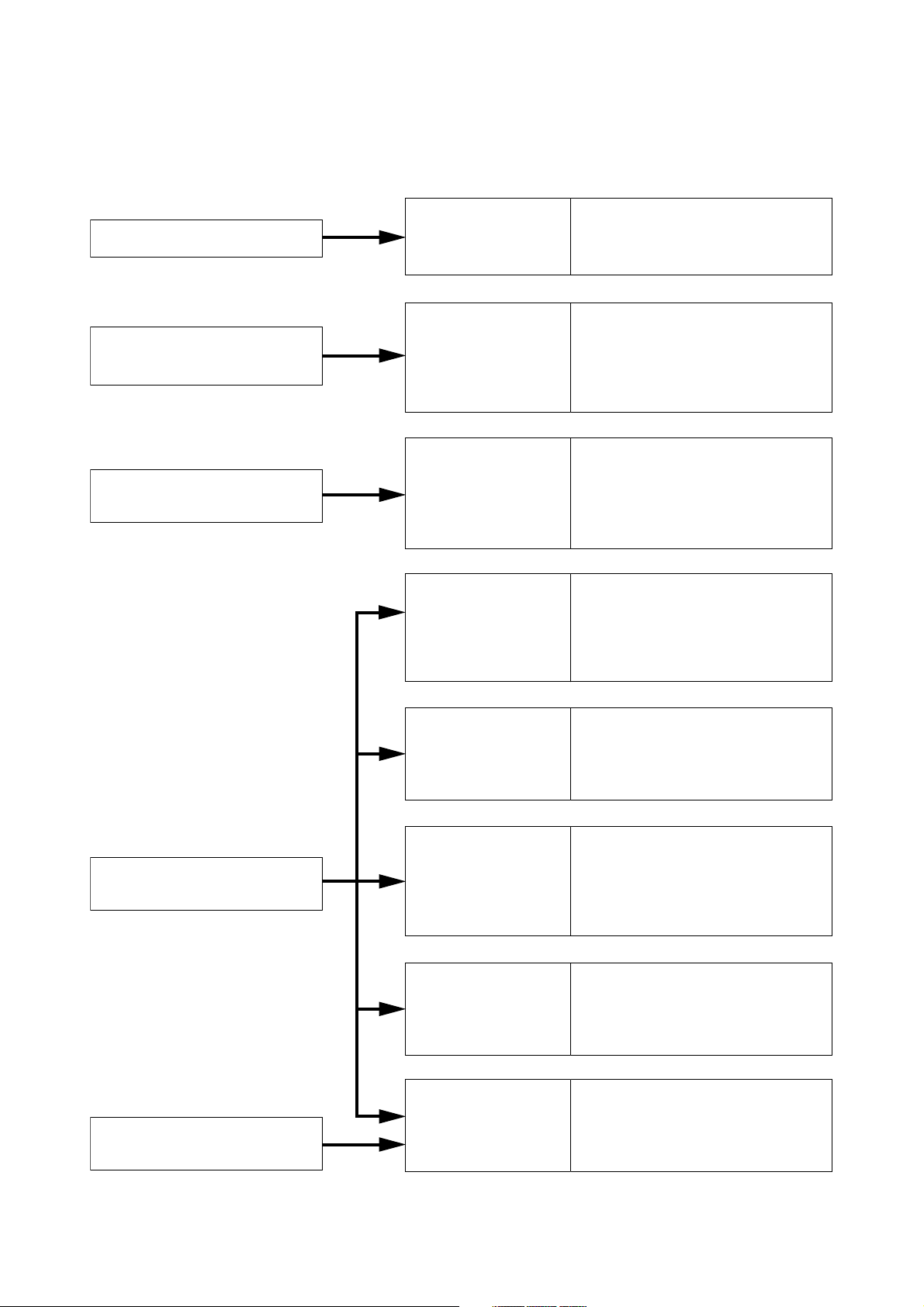
OPERATING INSTRUCTIONS CONFIGURATION
This operating instruction consists of Chapter 1 – 8 as follows.
Please read the necessary chapter as required.
To all users
To the person who operates
the equipment
To the person who installs and
wires the equipment
Chapter 1
General Description
Chapter 2
Function and
Operation
Chapter 3
Installation and
Wiring
Chapter 4
Before Performing
System Settings
• System Configuration
• Nomenclature and Functions
• System Function
• Basic Usage
• Conversation Functions and their
Operations
• Paging Function and Operation
• Other Functions and Operation
• Installation of the Exchange
• Installation of the Multi Interface
Unit
• Installation of Stations
• Wiring
• System Setting Items and Initial
Values
• Turning the system's Power
Switch ON
• Network Settings using a PC
To the person who designs
and maintains the system
To the person who installs and
wires the equipment
Chapter 5
System Settings by
Software
Chapter 6
System Settings
Using the Browser
Chapter 7
Multifunctional Station
Menu Screen Operation
(N-8000MS only)
Chapter 8
Appendix
• General Description
• Installation and Activating
• Equipment Scan
• System Settings
• Starting the Browser
• Network Settings
• Operating Status Indication,
Operation Log Indication
• System Administration
• Menu Items
• Entering Maintenance screen
• Settings
•
Basic Knowledge About Networks
• Trouble Occurs
•
Indicator Status & Troubleshooting
• Specifications
Page 13

Chapter 1
GENERAL DESCRIPTION
This chapter describes the Exchange and Multi interface unit system configurations,
station types, and functions of the N-8000 Series Packet Intercom System.
Page 14

1-2
Chapter 1: GENERAL DESCRIPTION
1. GENERAL DESCRIPTION
The N-8000 Series is a packet intercom system (IP network compatible intercom) employing packet audio
technology*1. By connecting IP intercom exchanges (which can connect up to 16 stations per exchange) and
Multi interface units to a network (LAN or WAN), an optimal system can be constructed for in-house or wide
area information communications such as duplex conversations between stations, periodical broadcasts, and
BGM broadcasts. Since up to 80 exchanges and multi interface units can be combined, systems of up to a
total of 1,280 stations can be realized. The system's "echo cancellation"*2feature makes hands-free duplex
conversation possible (conversations made without using a handset at both parties) between stations. In
addition, the multi interface unit features a contact bridge function to be performed by way of contact input and
output control.
*1Technology related to audio transmission over a network.
*2A circuit that prevents acoustic feedback or echo generated when the voice output from the station's
internal speaker enters the microphone.
Warning
This is a class A product. In a domestic environment this product may cause radio interference in which case
the user may be required to take adequate measures.
2. FEATURES
• Exchanges and Multi interface units can be distributed over a data communications network.
• Can be connected to an existing local area network (LAN) or wide-area network (WAN). The system can
also be easily connected to fiber-optic networks without restrictions on operating distance.
• The dedicated software program enables centralized control with a personal computer.
• System maintenance (verifying operation log and Line supervision) can also be performed with a personal
computer and Internet browser.
• Can be connected to the Exchange of the EXES-2000 or EXES-6000 Intercom System by a tie-line, or the
PBX exchange via the OD (out-band-dialing) trunk.
• The Multi interface unit can interlock with an electronic lock system or CCTV surveillance system by way of
contact input/output control function.
Page 15

1-3
Chapter 1: GENERAL DESCRIPTION
3. SPECIFICATIONS
Number of Units
Connectable to LAN: Maximum 80 (a total of Exchanges and Multi interface units)
Line Capacity: Maximum 1,280 (80 Exchanges x 16 stations per Exchange)
Speech Link Capacity
(Single Exchange): 4 links
(Exchange to Exchange): Speech Link: maximum 8 links, Multicast paging Link:maximum 4 links,
Unicast paging: 1 link (Simultaneous access capacity)
(Multi Interface): 2 links
Speech: Maximum 2 links
Audio input: Maximum 2 links
Audio output: Maximum 2 links
Note
The above links can be simultaneously used.
(Refer to the table on p. 1-6.)
Simultaneous access capacity for paging links
Multicast paging: Maximum 2 links
Unicast paging: 1 link
Paging Zones: Maximum 160 (When 80 Exchanges or Multi interface units are connected)
Paging Zone Via Network: Maximum 79 (Multicast paging), Maximum 16 (Unicast paging)
BGM Input: Maximum 8 channels (Number of inputs per exchange)
PBX Interface: Maximum 160 (When 80 Multi interface units are connected)
Tie-line Interface: Maximum 160 (When 80 Multi interface units are connected)
External Contact Output: Maximum 1,280 (When 80 Multi interface units are connected)
External Contact Input: Maximum 1,280 (When 80 Multi interface units are connected)
System Settings: Personal computer setting using a dedicated software program (over LAN)
(Network Related)
Voice Delay Time: 80 or 320 ms, selectable
Connection Delay Time: Maximum 1 second (When Multicast paging is made to 79 zones)
Usage Bandwidth: Maximum 2.08 Mbps (one way)/When Unicast paging is made to 16 zones
Maximum 130 kbps (two-way)/one call
Page 16
1-4
Chapter 1: GENERAL DESCRIPTION
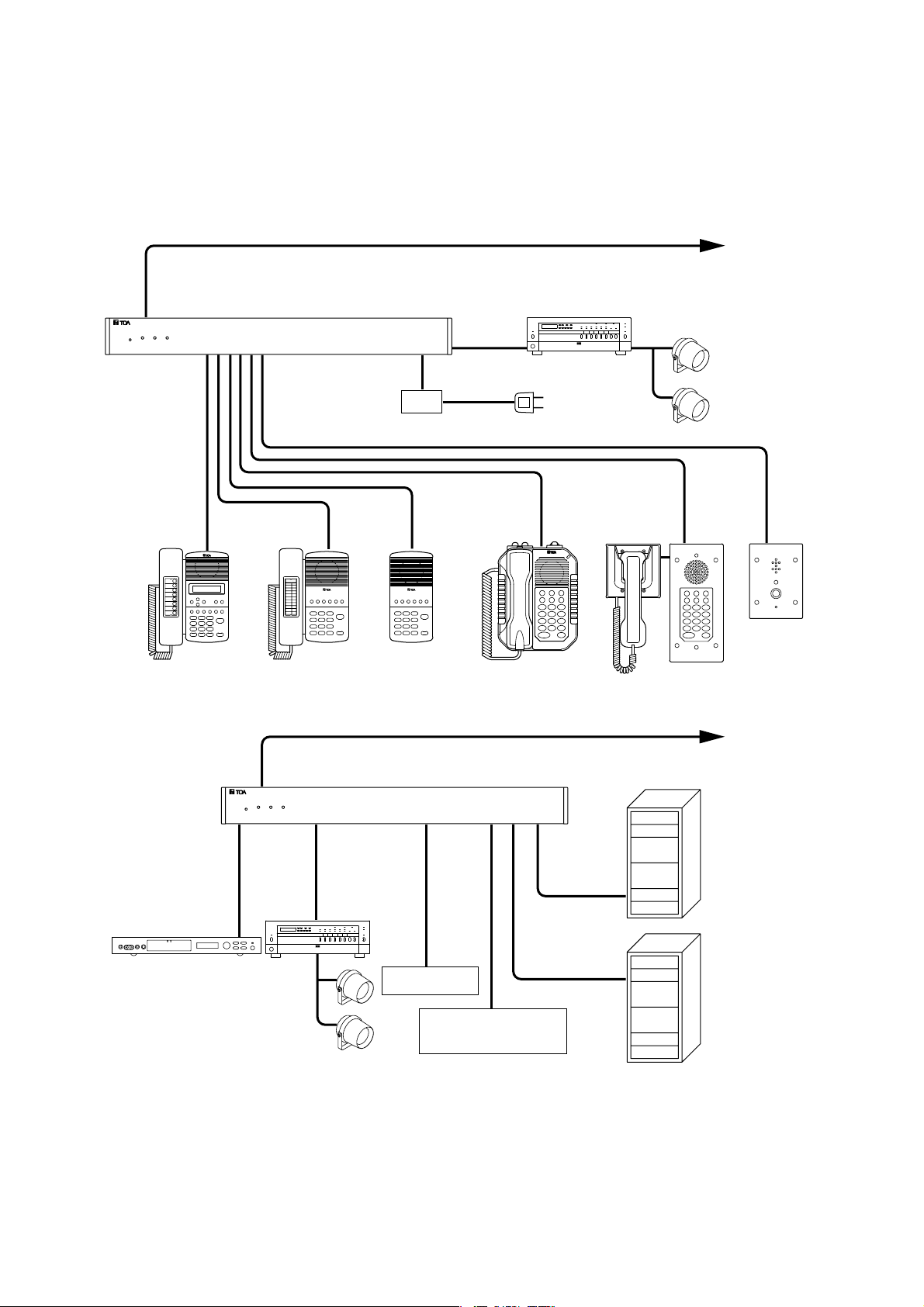
4. SYSTEM CONFIGURATION
4.1. System Configuration Example
This system consists of the following equipment.
To LAN
N-8000EX
UPS
(Uninterruptible power supply system)
N-8000MS N-8010MS N-8020MS N-8031MS N-8050DSN-8011MS
Amplifier
To AC Mains
Speaker
RS-191
To LAN
BGM player, digital
announcer, or other
sound source
Amplifier
Speaker
Contact input
Contact output
(door remote control)
N-8000MI
EXES-2000
EXES-6000
PBX
Page 17

1-5
Chapter 1: GENERAL DESCRIPTION
4.1.1. Exchange
N-8000EX: IP Intercom Exchange
4.1.2. Peripheral Components
N-8000MI: Multi Interface Unit
E-7000TB: 40-Station Terminal Board
4.1.3. Stations
N-8000MS: Multifunctional Master Station
N-8010MS: Standard Master Station
N-8011MS: Standard Hands-Free Master Station
N-8020MS: Industrial-Use Master Station
N-8031MS: Flush-Mount Master Station
RS-191: Option Handset
N-8050DS: Door Station
4.1.4. Others
YC-280: Wall mounting bracket for the N-8000MS/-8010MS/-8020MS
YC-290: Wall mounting bracket for the N-8011MS
YC-241 Back box for the N-8031MS
YC-251: Wall-mount box for the N-8031MS
YC-150: Back box for the N-8050DS
YS-13A: Wall-mount box for the N-8050DS
CR-273: Equipment Rack
CR-413: Equipment Rack
Page 18
1-6
Chapter 1: GENERAL DESCRIPTION
4.2. Component Description
4.2.1. Exchange
[N-8000EX IP Intercom Exchange]
The Exchange permits connection of up to sixteen N-8000 Series stations and features two outputs for public
address paging. The exchange is equipped with a networking interface, allowing connection with other IP
intercom exchanges and multi interface units. The Exchange can be mounted in an EIA standard rack (1U), to
a wall or installed on a desk.
4.2.2. Peripheral components
[N-8000MI Multi Interface Unit]
Having 2 channels each for audio input and output, and 16 contacts each for control input and output, the N8000MI performs the following interface functions*.
• Tie-line interface for connection with the EXES-2000 and EXES-6000 systems.
• PBX interface for connection with the PBX via the OD trunk.
• PA paging interface for connection with PA equipment
• External input broadcast interface for connection with a music player (chime unit) or paging
microphone irrespective of with or without remote control function.
• Interface to control an indicator or external equipment such as a CCTV's switcher using relay contacts.
The N-8000MI also features Network interface for connection with an IP intercom exchange or other Multiinterface unit.
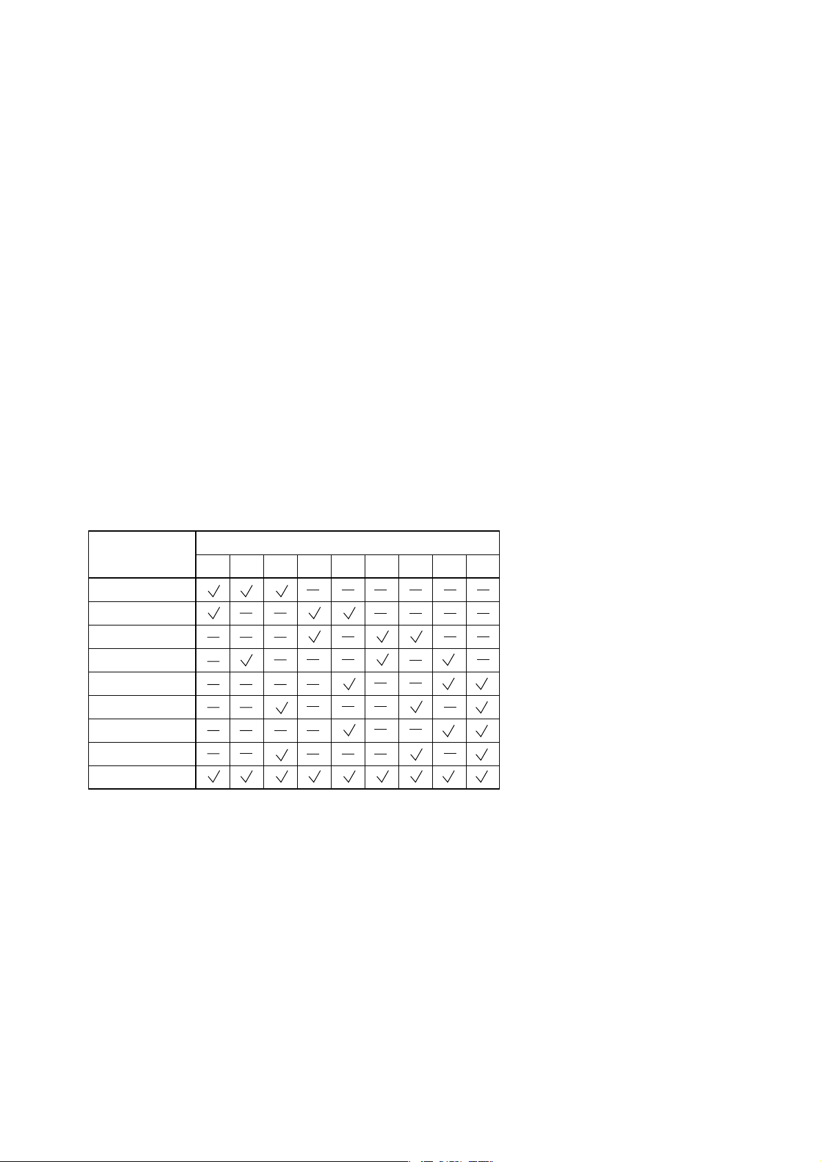
* The interface functions can be combined in the following 9 patterns.
[40-Station Terminal Board E-7000TB]
The E-7000TB is a clip type terminal board for connecting station lines to each exchange. Up to 40 lines
(twisted pair cables) can be connected. The optional YC-105 clipping tool is required for wiring. The E-7000TB
is rack-mountable (3U size).
Interface function
PBX 1
PBX 2
Tie-line 1
Tie-line 2
Audio output 1
Audio output 2
Audio input 1
Audio input 2
Contact IN/OUT
12345678
Combination pattern
9
Page 19

1-7
Chapter 1: GENERAL DESCRIPTION
*1The front operation panel can be inclined 16° from the desk surface by attaching the YC-280 Wall Mounting
Bracket to its bottom surface.
*2The front operation panel can be inclined 16° from the desk surface by attaching the YC-290 Wall Mounting
Bracket to its bottom surface.
*3A dedicated YC-280 Wall Mounting Bracket is required.
*4A dedicated YC-290 Wall Mounting Bracket is required.
*5Permits handset conversation when used in conversation with the RS-191 Option Handset
*6A dedicated YC-241 Back Box is required.
*7A dedicated YC-251 Wall-Mount Box is required.
*8A dedicated YC-150 Back Box is required.
*9A dedicated YS-13A Wall-Mount Box is required.
4.2.4. Others
[Equipment Racks CR-273 and CR-413]
The Exchange, 40-station terminal board, and other equipment components are mounted in these racks.
4.2.3. Stations
Type of Stations
N-8000MS: Multifunctional
Master Station
N-8010MS: Standard
Master Station
Speech Method
Handset
Handsfree
Headset
Desk top
*1
*1
Specification
Installation Method
Wall
Flush-
hanging
mounting
*3
*3
Wall
surface
mounting
LCD
Display
Autodialing
External
speaker
External
control
External
dial input
N-8011MS: Standard
Hands-Free Master Station
N-8020MS: Industrial-Use
Master Station
N-8031MS: Flush-Mount
Master Station
N-8050DS: Door Station
*2
*1
*5
*4
*3
*6
*7
*8
*9
Page 20
1-8
Chapter 1: GENERAL DESCRIPTION
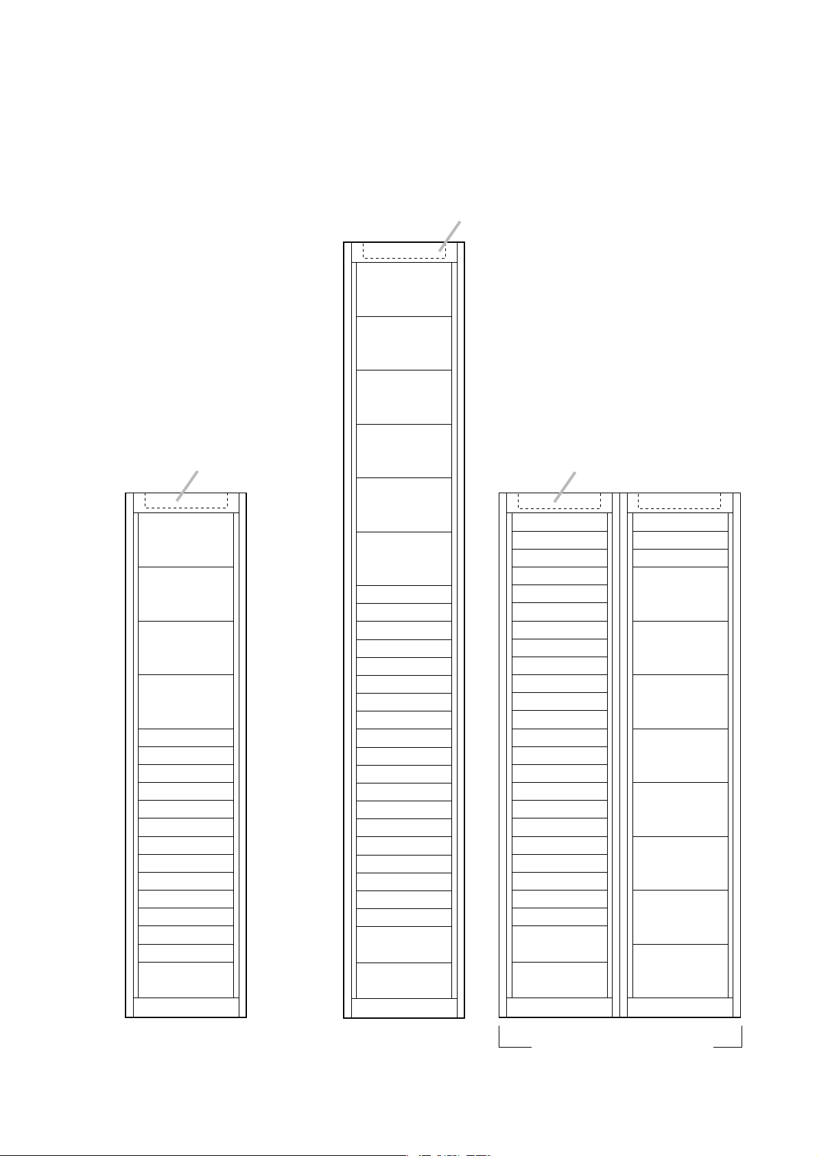
4.3. Rack Mounting Examples for Exchanges
4.3.1. A 128-line exchange system
One CR-273 Equipment Rack is
used.
4.3.2. A 192-line exchange system
One CR-413 Equipment Rack is
used.
4.3.3. A 256-line exchange system
Two CR-273 Equipment Racks are
used.
Blower unit
(BU-412)
Terminal board
(E-7000TB)
Terminal board
(E-7000TB)
Terminal board
(E-7000TB)
Terminal board
(E-7000TB)
Exchange (N-8000EX)
Exchange (N-8000EX)
Perforated panel
Exchange (N-8000EX)
Exchange (N-8000EX)
Perforated panel
Exchange (N-8000EX)
Exchange (N-8000EX)
Perforated panel
Exchange (N-8000EX)
Exchange (N-8000EX)
Perforated panel
Switching hub
Power distributor
Blower unit
(BU-412)
Terminal board
(E-7000TB)
Terminal board
(E-7000TB)
Terminal board
(E-7000TB)
Terminal board
(E-7000TB)
Terminal board
(E-7000TB)
Terminal board
(E-7000TB)
Exchange (N-8000EX)
Exchange (N-8000EX)
Perforated panel
Exchange (N-8000EX)
Exchange (N-8000EX)
Perforated panel
Exchange (N-8000EX)
Exchange (N-8000EX)
Perforated panel
Exchange (N-8000EX)
Exchange (N-8000EX)
Perforated panel
Exchange (N-8000EX)
Exchange (N-8000EX)
Perforated panel
Exchange (N-8000EX)
Exchange (N-8000EX)
Perforated panel
Switching hub
Power distributor
Power distributor
Blower unit
(BU-412)
Perforated panel
Exchange (N-8000EX)
Exchange (N-8000EX)
Perforated panel
Exchange (N-8000EX)
Exchange (N-8000EX)
Perforated panel
Exchange (N-8000EX)
Exchange (N-8000EX)
Perforated panel
Exchange (N-8000EX)
Exchange (N-8000EX)
Perforated panel
Exchange (N-8000EX)
Exchange (N-8000EX)
Perforated panel
Exchange (N-8000EX)
Exchange (N-8000EX)
Perforated panel
Exchange (N-8000EX)
Exchange (N-8000EX)
Perforated panel
Switching hub
Power distributor
Power distributor
Perforated panel
Exchange (N-8000EX)
Exchange (N-8000EX)
Terminal board
(E-7000TB)
Terminal board
(E-7000TB)
Terminal board
(E-7000TB)
Terminal board
(E-7000TB)
Terminal board
(E-7000TB)
Terminal board
(E-7000TB)
Terminal board
(E-7000TB)
Terminal board
(E-7000TB)
256-line exchange (CR-273)128-line exchange (CR-273) 192-line exchange (CR-413)
Page 21
1-9
Chapter 1: GENERAL DESCRIPTION
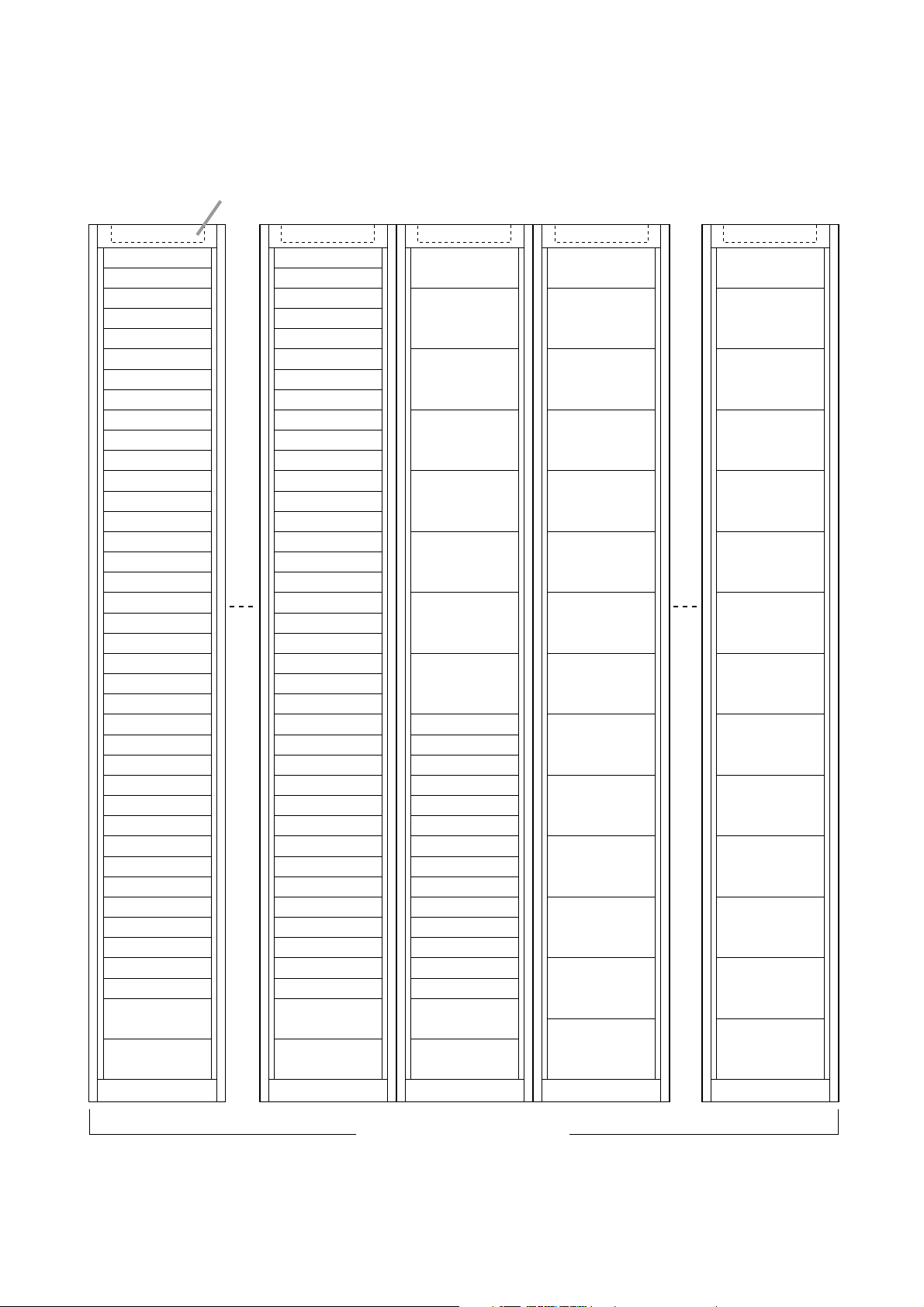
4.3.4. A 1280-line exchange system
Seven CR-413 Equipment Racks are used.
1280-line exchange (CR-413)
Power distributor
Power distributor
Switching hub
Perforated panel
Exchange (N-8000EX)
Exchange (N-8000EX)
Perforated panel
Exchange (N-8000EX)
Exchange (N-8000EX)
Perforated panel
Exchange (N-8000EX)
Exchange (N-8000EX)
Perforated panel
Exchange (N-8000EX)
Exchange (N-8000EX)
Perforated panel
Exchange (N-8000EX)
Exchange (N-8000EX)
Perforated panel
Exchange (N-8000EX)
Exchange (N-8000EX)
Perforated panel
Exchange (N-8000EX)
Exchange (N-8000EX)
Perforated panel
Exchange (N-8000EX)
Exchange (N-8000EX)
Perforated panel
Exchange (N-8000EX)
Exchange (N-8000EX)
Perforated panel
Exchange (N-8000EX)
Exchange (N-8000EX)
Perforated panel
Exchange (N-8000EX)
Exchange (N-8000EX)
Perforated panel
Exchange (N-8000EX)
Exchange (N-8000EX)
Power distributor
Power distributor
Switching hub
Perforated panel
Exchange (N-8000EX)
Exchange (N-8000EX)
Perforated panel
Exchange (N-8000EX)
Exchange (N-8000EX)
Perforated panel
Exchange (N-8000EX)
Exchange (N-8000EX)
Perforated panel
Exchange (N-8000EX)
Exchange (N-8000EX)
Perforated panel
Blank panel
Blank panel
Blank panel
Blank panel
Blank panel
Blank panel
Blank panel
Terminal board
(E-7000TB)
Terminal board
(E-7000TB)
Terminal board
(E-7000TB)
Terminal board
(E-7000TB)
Terminal board
(E-7000TB)
Terminal board
(E-7000TB)
Terminal board
(E-7000TB)
Terminal board
(E-7000TB)
Terminal board
(E-7000TB)
Terminal board
(E-7000TB)
Terminal board
(E-7000TB)
Terminal board
(E-7000TB)
Terminal board
(E-7000TB)
Terminal board
(E-7000TB)
Blank panel
Terminal board
(E-7000TB)
Terminal board
(E-7000TB)
Terminal board
(E-7000TB)
Terminal board
(E-7000TB)
Terminal board
(E-7000TB)
Terminal board
(E-7000TB)
Terminal board
(E-7000TB)
Terminal board
(E-7000TB)
Terminal board
(E-7000TB)
Terminal board
(E-7000TB)
Terminal board
(E-7000TB)
Terminal board
(E-7000TB)
Terminal board
(E-7000TB)
Blank panel
Rack No. 1 No. 3 No. 4 No. 5 No. 7
Blower unit
(BU-412)
Page 22
1-10
Chapter 1: GENERAL DESCRIPTION
[Rear]
5. NOMENCLATURE AND FUNCTIONS
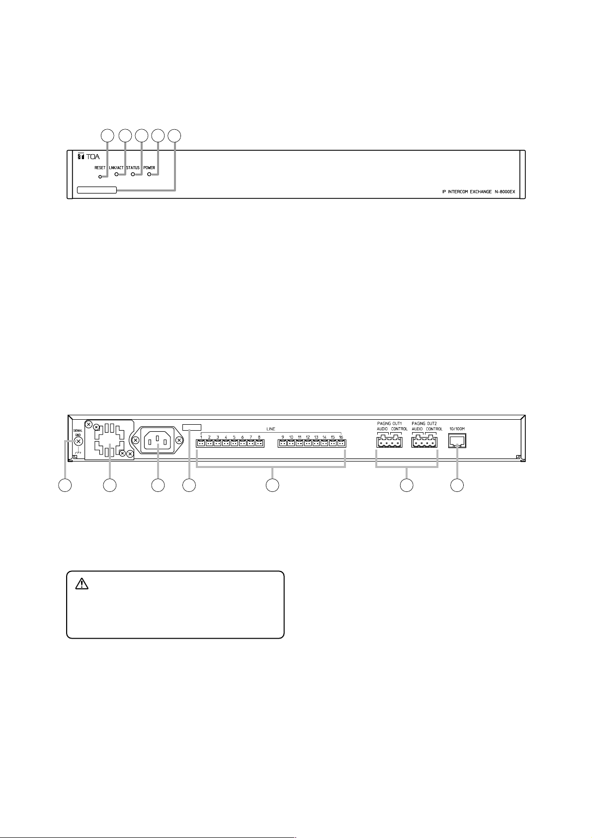
5.1. N-8000EX IP Intercom Exchange
[Front]
1. Reset key [RESET]
Pressing this key reactivates the exchange.
2. LNK/ACT indicator [LNK/ACT] (Green)
Lights when connected to a network, and flashes
while transmitting or receiving data.
3. Status indicator [STATUS] (Red)
Continuously lights while data is written to an
internal storage medium (FlashMemory), and
flashes to indicate such exchange malfunctions as
cooling fan failure. (Refer to p. 8-5.)
4. Power indicator [POWER] (Green)
Lights when power is supplied to the exchange.
5. MAC address
This is the address* used by the exchange. Since
the relationship of each exchange location to its
MAC address is established when setting the
network attributes, keep track of this relationship
for later use.
*The inherent address assigned to each network
component, expressed in 12-digit hexadecimal
notation.
1 2 3 4
5
00-05-F9-FF-00-00
6. Functional earth terminal [SIGNAL GND]
Ground this terminal.
Note: This terminal is not for protective earth.
7. Cooling fan
8. AC inlet
Connects the supplied power cord.
Note
If there is a danger of lightning strikes, insert an
appropriate surge arrester into the power line.
9. Cord clamp
Pass the power cord through this clamp to ensure
that the plug cannot be pulled out when the unit is
mounted to a wall. (Refer to p. 3-4)
10. Line connection terminals [LINE]
Connect the station to each terminal using a
mini-clamp connector. (Refer to p. 3-30)
11. Paging output terminals [PAGING OUT 1/2,
AUDIO/CONTROL]
Includes audio outputs (0 dB*, 600 Ω, balanced)
and contact outputs (no-voltage make, 24 V DC,
0.5 A MAX).
Connect using a removable terminal plug.
(Refer to p. 3-30)
12. Network connection terminal [10/100M]
Connects a 10BASE-T- or 100BASE-TXcompatible network. (Ethernet RJ45 jack)
* 0 dB = 1 V
CAUTION
Do not block the fan exhaust vent. Doing so
may cause heat to build up inside the unit and
result in fire.
6 7 8 9 10 11
12
Page 23
1-11
Chapter 1: GENERAL DESCRIPTION
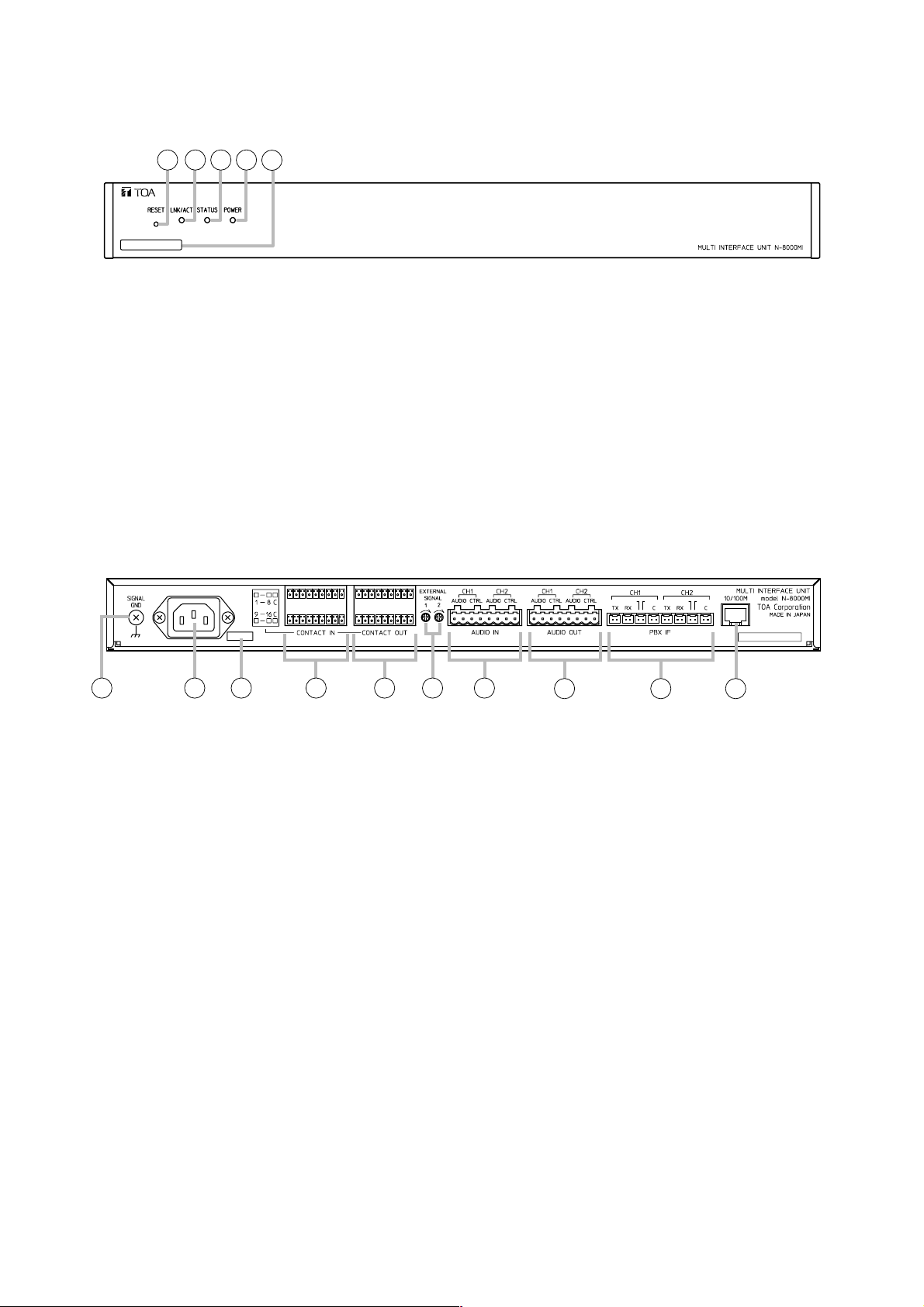
5.2. N-8000MI Multi Interface Unit
[Front]
[Rear]
1. Reset key [RESET]
Pressing this key reactivates the exchange.
2. LNK/ACT indicator [LNK/ACT] (Green)
Lights when connected to a network, and flashes
while transmitting or receiving data.
3. Status indicator [STATUS] (Red)
Continuously lights while data is written to an
internal storage medium (FlashMemory).
Flashes if there is a failure. (Refer to p. 8-5.)
4. Power indicator [POWER] (Green)
Lights when power is supplied to the unit.
5. MAC address
This is the address*1used by the unit. Since the
relationship of each exchange location to its MAC
address is established when setting the network
attributes, keep track of this relationship for later
use.
*1The inherent address assigned to each network
component, expressed in 12-digit hexadecimal
notation.
6. Functional earth terminal [SIGNAL GND]
Be sure to ground this terminal unless the unit
connects to a PBX.
Note: This terminal is not for protective earth.
7. AC inlet
Connects the supplied power cord.
Note
If there is a danger of lightning strikes, insert an
appropriate surge arrester into the power line.
8. Cord clamp
Pass the power cord through this clamp to
ensure that the plug does not pull out when the
unit is mounted to a wall. (Refer to p. 3-7.)
9. Contact input terminals [CONTACT IN]
No-voltage make contact inputs.
Short-circuit current: 10 mA, Open-circuit
voltage: 12 V
10. Contact output terminals [CONTACT OUT]
Relay contact outputs.
Withstand voltage: 24 V DC, Control current:
Maximum 0.5 A
11.Audio input level controls [EXTERNAL
SIGNAL 1, 2]
Use these controls to adjust the audio input
levels for channels 1 and 2 according to the input
sources.
12. Audio input terminal [AUDIO IN]
Includes audio inputs (maximum 0 dB*2, over 10
kΩ, balanced) and contact inputs (no-voltage
make contact, short-circuit current: 10 mA, opencircuit voltage: 12 V).
13. Audio output terminal [AUDIO OUT]
Includes audio outputs (maximum 0 dB*2, under
600 Ω, balanced) and control outputs (relay
contact withstand voltage: 24 V DC, control
current: maximum 0.5 A).
14. PBX interface terminal [PBX IF]
Connects to the Exchange of the EXES-2000 or
EXES-6000 system by a tie-line, or the PBX
exchange via the OD (out-band-dialing) trunk.
15. Network connection terminal [10/100M]
Connects to a 10BASE-T- or 100BASE-TXcompatible network. (Ethernet RJ45 jack)
*
2
0 dB = 1 V
1 2 3 4
00-05-F9-FF-00-00
5
ME ME
6 7 8 9 10 11
12
13 14 15
Page 24
1-12
Chapter 1: GENERAL DESCRIPTION
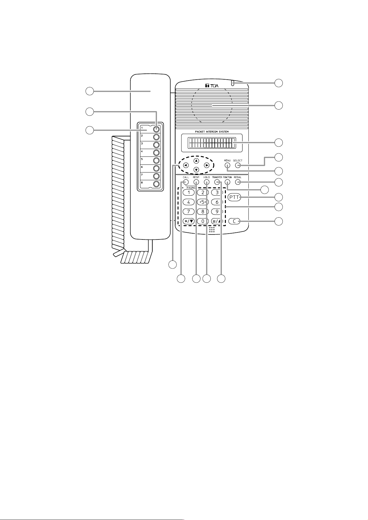
5.3. N-8000MS Multifunctional Master Station
[Top]
3
2
1
5
6
7
8
9
10
11
12
13
14
15 16 1817
4
1. Handset
Lift the handset for handset conversation. Lifting
the handset disconnects both the hands-free
microphone and the speaker.
2. Auto-dial key
Used to call or register the party to be called.
(Refer to p. 2-9.)
3. Auto-dial directory
Writes the auto-dial registration contents to this
directory.
4. Status indicator (Red)
Flashes when a call is received, continuously
lights during a conversation, and is off while in
standby mode. The indicator also continuously
lights while receiving a paging announcement.
5. Speaker
Outputs call tones and used for hands-free
conversations.
6. Liquid crystal display
Displays the dialed number or the number of a call
received in 2 lines of 16 digits. Pressing the Menu
key (8) displays the menu screen.
7. Selection key [SELECT]
Used for menu item selection or input value
confirmation.
8. Menu key [MENU]
Used for auto-dial registration (refer to p. 2-9) or
system settings. (Refer to Chapter 7.)
Page 25
1-13
Chapter 1: GENERAL DESCRIPTION
9. Redial key [REDIAL]
Permits the last called number to be dialed.
(Refer to p.2-6.)
10. Function key [FUNCTION]
Use this key to perform function settings such as
assigning call transfer recipients or programming
one-touch dialing.
11. Push-to-talk key [PTT]
Pressing this key while calling a party by means
of a continuous call tone permits a voice call to
be made. (Refer to p. 2-7.) Also, pressing this
key during a hands-free conversation establishes
a one-way conversation from the party who
pressed the key. (Refer to p. 2-5.)
12. Dial keys
Use these keys to make a call or set a function.
13. Clear key [C]
Terminates the conversation.
14. Arrow keys [ ][ ][ ][ ]
Use these keys to perform auto-dial registration
(refer to p. 2-9) or system settings (refer to
Chapter 7).
15. Paging key [CALL]
Makes a paging. (Refer to p. 2-22.)
16. Paging response key [RESP.]
Responds to a paging.
(Refer to p. 2-26.)
17. Hold key [HOLD]
Places the conversation on hold. (Refer to
p. 2-11.)
18. Transfer key [TRANSFER]
Used to transfer the current conversation to
another station. (Refer to p. 2-12.)
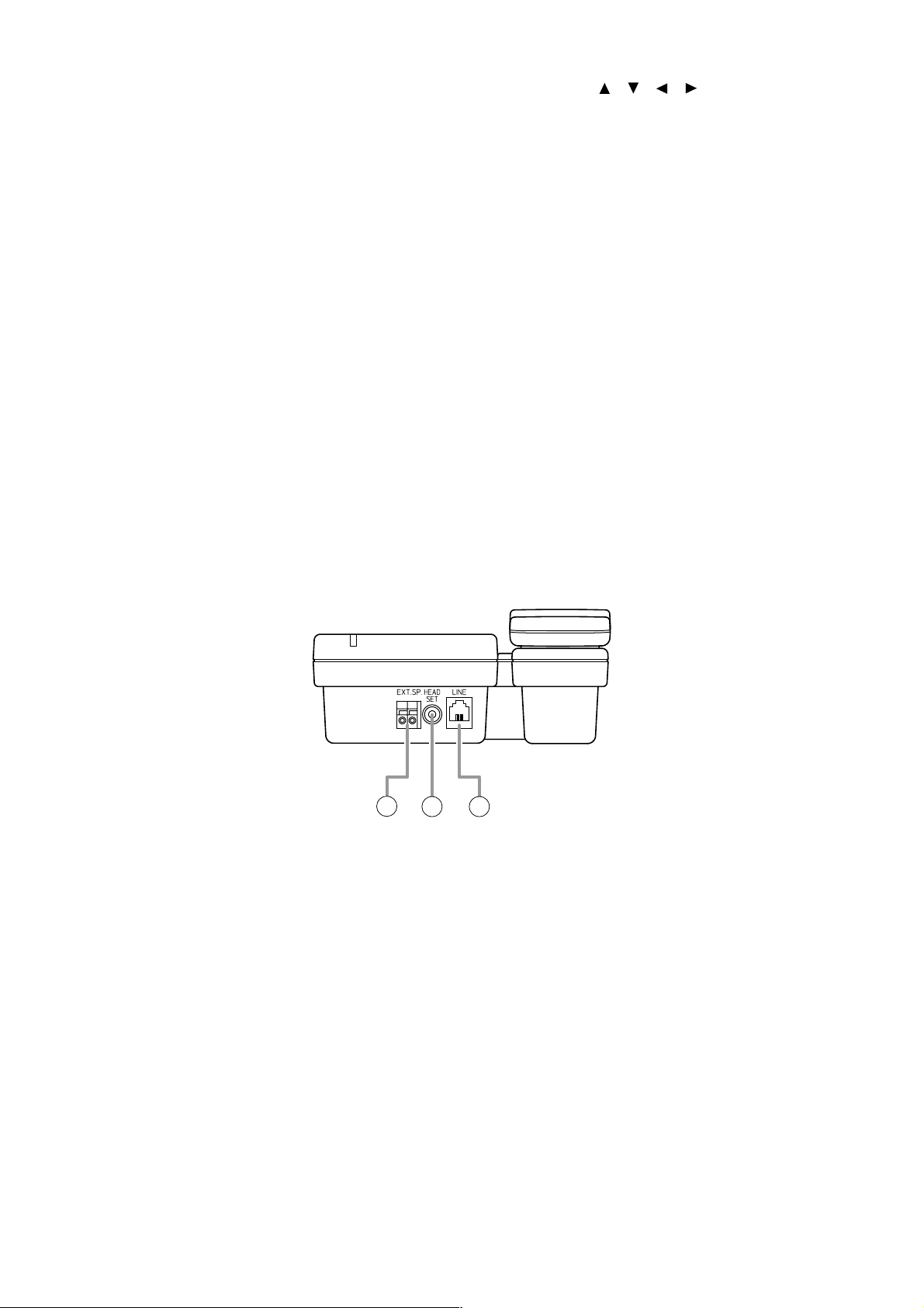
2120
19
19. External speaker terminal [EXT.SP.]
An external speaker (8 Ω, 0.6 W) can be
connected to this terminal. (Refer to p. 3-23.)
Shift the Speaker selector switch (22) located on
the bottom surface of the unit to the EXT.SP
position when using the external speaker.
20. Headset terminal [HEADSET]
Connects to a headset. Connection of the
headset disables the speaker.
21. Line connection terminal [LINE]
Connects to the exchange. (RJ11 modular jack)
[Rear]
Page 26
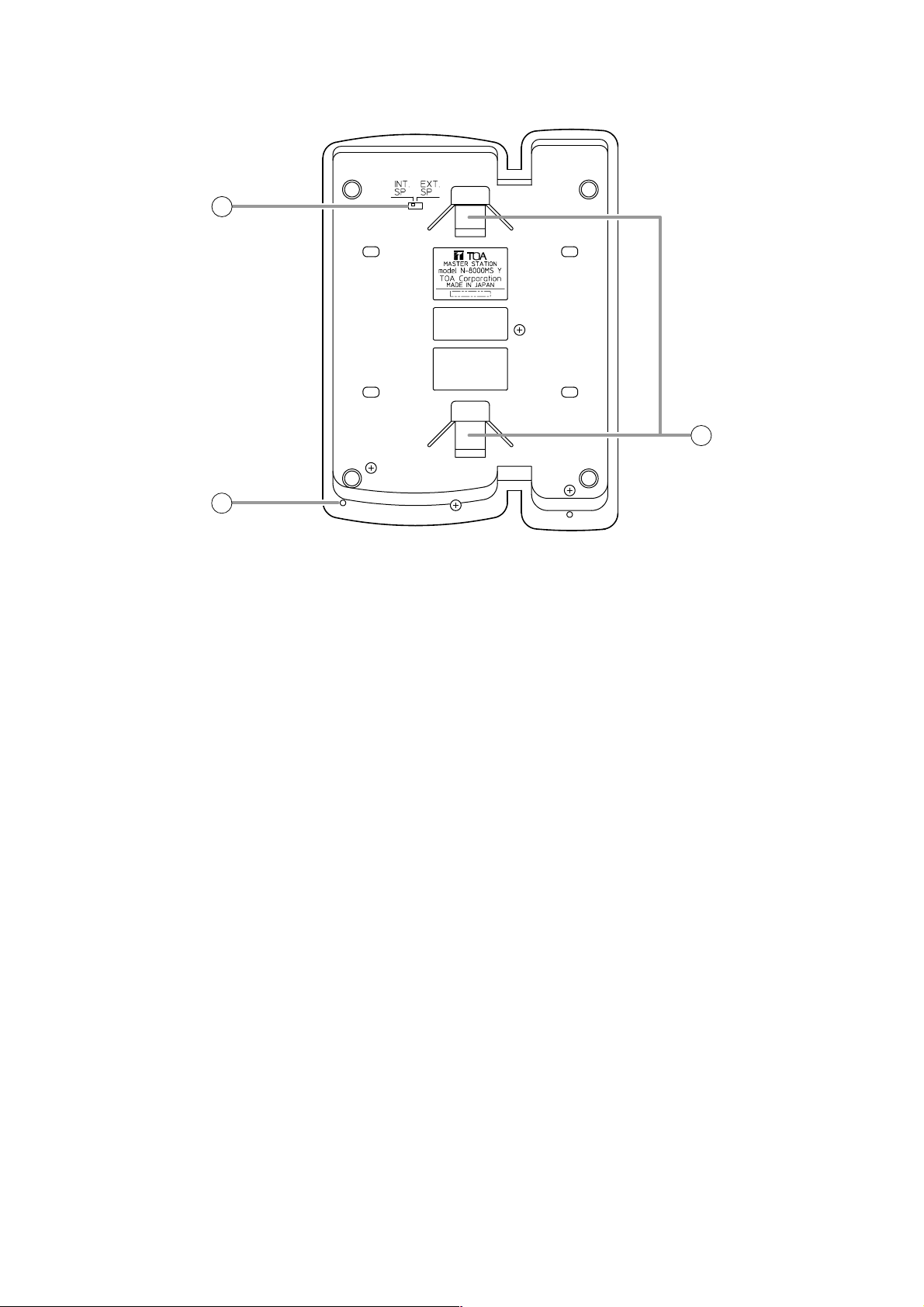
1-14
Chapter 1: GENERAL DESCRIPTION
22. Speaker selector switch [INT.SP/EXT.SP]
Used to select either an internal (INT.SP) or an
external (EXT.SP) speaker.
23. Microphone
Used for hands-free conversation.
Note
Avoid placing obstacles close to the microphone
that might block sound and prevent
conversations.
24. Wall bracket mounting slots
Hang the mounting bracket hooks to these slots
when using the YC-280 Wall Mounting Bracket.
(Refer to p. 3-9, p. 3-13.)
[Bottom]
24
23
22
Page 27
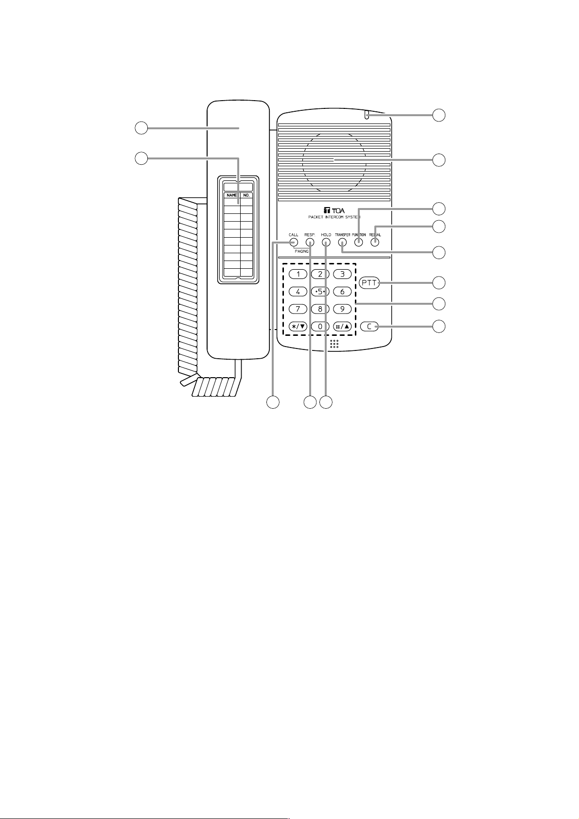
1-15
Chapter 1: GENERAL DESCRIPTION
2
1
9
10
11 12 13
3
4
5
6
7
8
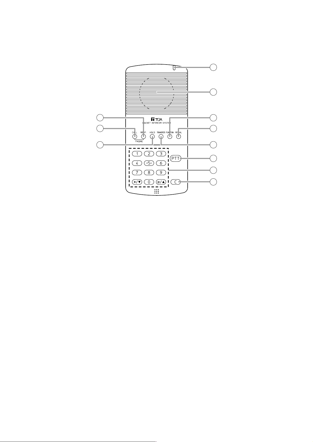
1. Handset
Lift the handset for handset conversation. Lifting
the handset disconnects both the hands-free
microphone and the speaker.
2. Dial directory
Writes the dial registration of the party to be called
to this directory.
3. Status indicator (Red)
Flashes when a call is received, continuously
lights during a conversation, and is off while in
standby mode. The indicator also continuously
lights while receiving a paging announcement.
4. Speaker
Outputs call tones and used for hands-free
conversations.
5. Function key [FUNCTION]
Use this key to perform function settings such as
assigning call transfer recipients or programming
one-touch dialing.
6. Redial key [REDIAL]
Permits the last called number to be dialed. (Refer
to p. 2-6.)
7. Transfer key [TRANSFER]
Used to transfer the current conversation to
another station. (Refer to p. 2-12.)
8. Push-to-talk key [PTT]
Pressing this key while calling a party by means of
a continuous call tone permits a voice call to be
made. (Refer to p. 2-7.) Also, pressing this key
during a hands-free conversation establishes a
one-way conversation from the party who pressed
the key. (Refer to p. 2-5.)
9. Dial keys
Use these keys to make a call or set a function.
10. Clear key [C]
Terminates the conversation.
11. Paging key [CALL]
Makes a paging. (Refer to p. 2-22.)
12. Paging response key [RESP.]
Responds to a paging.
(Refer to p. 2-26.)
13. Hold key [HOLD]
Places the conversation on hold.
(Refer to p. 2-11.)
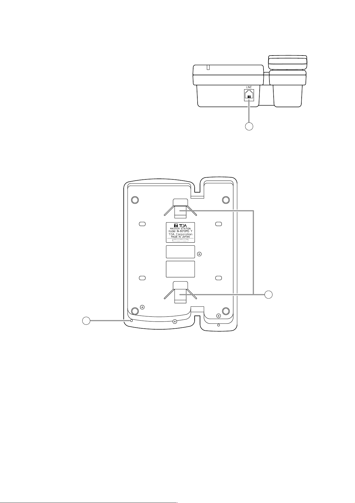
5.4. N-8010MS Standard Master Station
[Top]
Page 28
1-16
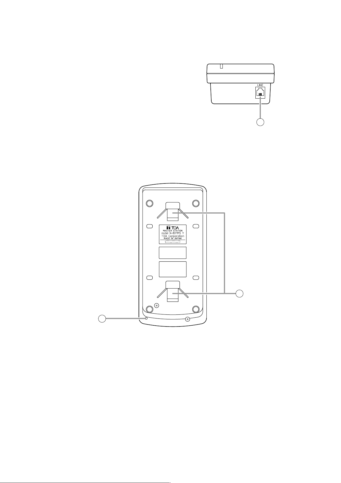
Chapter 1: GENERAL DESCRIPTION
16
15
[Rear]
15. Microphone
Used for hands-free conversation.
Note
Avoid placing obstacles close to the microphone
that might block sound and prevent
conversations.
16. Wall bracket mounting slots
Hang the hooks of the mounting bracket to these
slots when using the YC-280 Wall Mounting
Bracket. (Refer to p. 3-9, p. 3-13.)
14. Line connection terminal [LINE]
Connects to the exchange. (RJ11 modular jack)
14
[Bottom]
Page 29
1-17
Chapter 1: GENERAL DESCRIPTION
2
3
4
9
10
5
7
8
11
1
6
1. Paging response key [RESP.]
Responds to a paging. (Refer to p. 2-26.)
2. Paging key [CALL]
Makes a paging. (Refer to p. 2-22.)
3. Hold key [HOLD]
Places the conversation on hold.
(Refer to p. 2-11.)
4. Status indicator (Red)
Flashes when a call is received, continuously
lights during a conversation, and is off while in
standby mode. The indicator also continuously
lights while receiving a paging announcement.
5. Speaker
Outputs call tones and used for hands-free
conversations.
6. Function key [FUNCTION]
Use this key to perform function settings such as
assigning call transfer recipients or programming
one-touch dialing.
7. Redial key [REDIAL]
Permits the last called number to be dialed. (Refer
to p. 2-6.)
8. Transfer key [TRANSFER]
Used to transfer the current conversation to
another station. (Refer to p. 2-12.)
9. Push-to-talk key [PTT]
Pressing this key while calling a party by means of
a continuous call tone permits a voice call to be
made. (Refer to p. 2-7.) Also, pressing this key
during a hands-free conversation establishes a
one-way conversation from the party who pressed
the key. (Refer to p. 2-5.)
10. Dial keys
Use these keys to make a call or set a function.
11. Clear key [C]
Terminates the conversation.
5.5. N-8011MS Standard Hands-free Master Station
[Top]
Page 30
1-18
Chapter 1: GENERAL DESCRIPTION
12
14
13
[Rear]
13. Microphone
Used for hands-free conversation.
Note
Avoid placing obstacles close to the microphone
that might block sound and prevent
conversations.
14. Wall bracket mounting slots
Hang the mounting bracket hooks to these slots
when using the YC-290 Wall mounting bracket.
(Refer to p. 3-11, p. 3-14.)
12. Line connection terminal [LINE]
Connects to the exchange. (RJ11 modular jack)
[Bottom]
Page 31

1-19
Chapter 1: GENERAL DESCRIPTION
2
1
11 12
3
4
5
9
10
6
7
8
1. Handset
Lift the handset for handset conversation. Lifting
the handset disconnects both the hands-free
microphone and the speaker.
2. Status indicator (Red)
Flashes when a call is received, continuously
lights during a conversation, and is off while in
standby mode. The indicator also continuously
lights while receiving a paging announcement.
3. Speaker
Outputs call tones and used for hands-free
conversations.
4. Paging key [CALL]
Makes a paging. (Refer to p. 2-22).
5. Paging response key [RESP.]
Responds to a paging. (Refer to p. 2-26)
6. Function key [FUNCTION]
Use this key to perform function settings such as
assigning call transfer recipients or programming
one-touch dialing.
7. Redial key [REDIAL]
Permits the last called number to be dialed. (Refer
to p. 2-6.)
8. Transfer key [TRANSFER]
Used to transfer the current conversation to
another station. (Refer to p. 2-12.)
9. Dial keys
Use these keys to make a call or set a function.
10. Hold key [HOLD]
Places the conversation on hold.
(Refer to p. 2-11.)
11. Push-to-talk key [PTT]
Pressing this key while calling a party by means
of a continuous call tone permits a voice call to
be made. (Refer to p. 2-7.) Also, pressing this
key during a hands-free
conversation establishes a one-way conversation
from the party who pressed the key.
(Refer to p. 2-5.)
12. Clear key [C]
Terminates the conversation.
5.6. N-8020MS Industrial-Use Master Station
[Top]
Page 32

1-20
Chapter 1: GENERAL DESCRIPTION
Figure of the terminal
where protection cover
is removed
Figure viewed from front center
18
17
16
14 15
Protection cover
13
[Rear]
13. Line connection cable [LINE]
Connects to the exchange. (3 m-length cable
with RJ11 modular plug)
Note: Do not remove the protection cover.
14. External speaker terminal [EXT.SP.]
An external speaker (8 Ω 0.6 W) can be
connected to this terminal. When connecting,
replace a protection cap with a supplied rubber
bushing. (Refer to p. 3-23.)
Shift the Speaker selector switch (16) located on
the bottom surface of the unit to the EXT.SP
position when using the external speaker.
15. Contact output terminal [CONTACT OUT]
Permits connection of a device to indicate the
calling station.
This terminal closes only while a call is being
made or received. (Output capacity: 30 V DC
and 50 mA.)
When connecting, replace a protection cap with
a supplied rubber bushing. (Refer to p. 3-23.)
16. Speaker selector switch [INT.SP/EXT.SP]
The internal switch is exposed if the protection
cover is removed.
Used to select either an internal (INT.SP) or an
external (EXT.SP) speaker. After shifting the
selector switch, fit the protection cover back into
place.
17. Microphone
Used for hands-free conversation.
Note
Avoid placing obstacles close to the microphone
that might block sound and prevent
conversations.
18. Wall bracket mounting slots
Hang the mounting bracket hooks to these slots
when using the YC-280 Wall mounting bracket.
(Refer to p. 3-9, p. 3-13.)
[Bottom]
Page 33

1-21
Chapter 1: GENERAL DESCRIPTION
5.7. N-8031MS Flush-Mount Master Station
[Front] [Rear]
1. Status indicator (Red)
Flashes when a call is received, continuously
lights during a conversation, and is off while in
standby mode. The indicator also continuously
lights while receiving a paging announcement.
2. Paging key [CALL]
Makes a paging. (Refer to p. 2-22.)
3. Hold key [HOLD]
Places the conversation on hold. (Refer to p. 2-11.)
4. Push-to-talk key [PTT]
Pressing this key while calling a party by means of
a continuous call tone permits a voice call to be
made. (Refer to p. 2-7.) Also, pressing this key
during a hands-free conversation establishes a
one-way conversation from the party who pressed
the key.
(Refer to p. 2-5.)
5. Speaker
Outputs call tones and used for hands-free
conversations.
6. Paging response key. [RESP.]
Responds to a paging. (Refer to p. 2-26.)
7. Function key [FUNCTION]
Use this key to perform function settings such as
assigning call transfer recipients or programming
one-touch dialing.
8. Redial key [REDIAL]
Permits the last called number to be dialed.
(Refer to p. 2-6.)
9. Transfer key [TRANSFER]
Used to transfer the current conversation to
another station. (Refer to p. 2-12.)
10. Dial keys
Use these keys to make a call or set a function.
11. Clear key [C]
Terminates the conversation.
12. Microphone
Used for hands-free conversation.
13. Line connection terminals [1, 2]
Connect to the exchange. (Pin header)
Note
The removable terminal plug (2P) is factory-
attached. (Refer to p. 3-22.)
1
2 1
5
13
14
6
2
3
7
8
9
10
7
8
15
4
11
COM
9
C
12
Page 34

1-22
Chapter 1: GENERAL DESCRIPTION
14. Handset connection terminals [CN302]
A dedicated RS-191 Option Handset can be
connected. (Refer to p. 3-24.)
15. External dial input terminals [CN306]
An external switch such as a footswitch can be
connected. (Refer to p. 3-25.)
One-touch dial function needs be programmed
when using the external switch. (Refer to p. 2-
10.)
5.8. N-8050DS Door Station
[Front] [Rear]
1. Speaker
Outputs call tones and used for hands-free
conversations.
2. Status indicator (Red)
Flashes when a call is received, continuously
lights during a conversation, and is off while in
standby mode. The indicator also continuously
lights while receiving a paging announcement.
3. Call button
Used to call the pre-programmed master station.
4. Microphone
Used for hands-free conversation.
5. Line connection terminal [LINE]
Connects to the exchange. (Terminal block)
(Refer to p. 3-22.)
6. Contact output terminals [H, C]
External equipment such as an electronic lock can
be connected.
Can be shorted momentarily by the operation from
the conversation party's master station.
(Output capacity: 30 V DC and 50 mA)
(Refer to p. 3-25.)
1
2
5
6
3
4
Page 35

1-23
Chapter 1: GENERAL DESCRIPTION
Operation
Function
Conversation
Calls can be made or received by lifting the handset.
The desired party can be called by dialing its station
number.
Pressing the Redial key automatically redials the last
number called. Only the N-8000MS Multifunctional
Master Station permits selection from the most recent
10 numbers.
The last conversation partner can be recalled by
pressing the [#/ ] key regardless of whether the call
was made or received. Only the N-8000MS
Multifunctional Master Station permits selection from
the most recent 10 numbers.
Holding down the Push-to-talk key while making a call
by means of a continuous call tone permits a voice
calling to be made to the called station. The voice
calling reverts to the original continuous tone call when
the Push-to-talk key is released.
When a station is assigned to a call group, if the
station is called, all stations within that group are
simultaneously called by a continuous call tone
regardless of their call connection mode settings. If
any one of the stations within the group responds, calls
to the other stations stop.
Call
Handset
conversation
Individual call
Redialing
Recall
Voice calling
Group call
Permits conversations to be made without lifting the
handset when another party is called or when a call is
received in automatic connection mode.
Hands-free
conversation
Incoming
Call
Selection
Incoming calls are automatically connected after a
brief call tone (1 second) or without a call tone.
Calls continue with a continuous call tone (or without a
call tone) and a status indicator continuously flashes
as long as no response is made.
Automatic
connection
Continuous call
Description
Reference page
P. 2-5
P. 2-5
P. 2-6
P. 2-6
P. 2-7
P. 2-7
P. 2-8
P. 2-8
P. 2-8
Pressing the Push-to-talk key during a hands-free
conversation enables one-way conversation from the
party who pressed the Push-to-talk key. Conversation
flow is reversed when the key is released. This
function makes announcements and conversations
possible to areas with a high ambient noise level.
PTT conversation
P. 2-5
P. 5-38
P. 5-38
P. 5-38
Setting
6. SYSTEM FUNCTION TABLE
6.1. Basic Functions
The system consisting of Exchanges and stations makes the following functions available.
The pre-programmed master station can be called by
pressing the door station's call button.
Master call
P. 2-6
P. 5-40
Page 36

1-24
Chapter 1: GENERAL DESCRIPTION
Speed
Dialing
Auto-dialing
(N-8000MS only)
One-touch dialing
The dial operation (up to 20-digit numbers)
programmed into the station's auto dialer can be
performed by one-touch dialing.
The dial operation (up to 20-digit numbers)
programmed into the station's [7], [8], [9], [0] or offhook keys can be called by one-touch dialing.
P. 2-9
P. 2-10
P. 2-9
P. 2-10
P. 5-40
Function Description
Reference page
Operation
Setting
Mic Off
Call hold
When it is desirable to hold the line during a
conversation, if any dialing key ([0] – [9]) is pressed, the
microphone is disabled as long as the key is pressed.
Pressing the Hold key during a conversation places the
conversation on hold, transmitting a hold tone to both
parties. If the Hold key is pressed again, the hold mode
is cancelled, and the original conversation is restored.
Hold
P. 2-11
P. 2-11
Calls to a busy station are automatically transferred to
another designated station, if group hunting function is
set to the called station.
When no response is made to a call for a set period of
time, the call is automatically transferred to another
designated station.
Calls to stations are automatically transferred to
another designated station without sounding a call
tone. Two different modes are available: one is call
forwarding, in which calls are manually rerouted to the
selected station, and the other is time-based call
forwarding, which transfers calls only when the preset
time is reached.
Automatic
Transfer
Group hunting
Absence transfer
Call forwarding
Remote Response
Calls to a station can be answered by pressing the
Push-to-talk key of another station, provided both
stations are assigned to the same group.
If a called station is busy, as indicated by a busy tone,
pressing the [9] key transmits a short priority call tone,
then forcibly terminates the current conversation,
allowing the call to go through. Access to priority call
operation or refusal of priority calls can be set
individually for each station.
Executive Priority
Current conversations can be placed on hold to call a
third party by pressing the Transfer key. The original
conversation can be subsequently restored or
transferred to the third party after conclusion of the
second call.
Call transfer
P. 2-12
P. 2-14
P. 2-15
P. 2-16
P. 2-18
P. 2-20
P. 2-14
P. 5-26
P. 5-38
P. 2-15
P. 5-26
P. 5-38
P. 2-16
P. 2-17
P. 5-26
P. 5-38
P. 2-19
P. 5-45
P. 5-38
Calls can be made to one of the pre-programmed
zones.
Calls can be made to up to 10 zones of the preprogrammed multiple zones.
Calls can be made simultaneously to all of the preprogrammed zones.
Paging
Zone paging
Paging
All-call paging
P. 2-22
P. 2-23
P. 2-24
P. 5-42
P. 5-42
P. 5-42
Page 37

1-25
Chapter 1: GENERAL DESCRIPTION
Group Blocking
Arbitrary station groups (up to 31 groups) can be set
to permit or disallow calls between groups.
Time-Out
The duration of calls, conversations and paging can
be limited by pre-programming time intervals (10 –
990 seconds) for individual exchanges or multi
interface units.
P. 2-20
P. 2-21
Function Description
Reference page
Operation
Setting
Dialing the Paging Response key automatically
initiates a response to the paging last received.
Dialing the number assigned to paging response
automatically initiates a response to a next-to-last
paging.
Paging
Response
Automatic response
Zone number paging
P. 2-26
P. 2-27
P. 5-26
P. 5-26
P. 5-26
P. 5-43
Door Remote Control
(Only when the N-8050DS is
used)
Door station's contact output can be used to remotely
control external equipment such as electronic lock.
The contact output terminals can be shorted for a set
period of time by the dial operation to perform this
function from the master station engaged in
conversation with the door station.
P. 2-35
P. 5-26
Scan Monitor
The station can scan an arbitrary group of preprogrammed stations for auditory monitoring.
P. 2-28
Station Speaker Output Setting
Permits adjustment of the station speaker sound
volume.
P. 2-4
Ambient Noise Control
Automatically measures the ambient noise level of the
station and sets the station for proper hands-free
conversation.
P. 2-5
P. 5-41
P. 5-38
Page 38

1-26
Chapter 1: GENERAL DESCRIPTION
6.2. Multi Interface Unit's Functions
The addition of the N-8000MI Multi-interface unit makes the following functions available:
External Input Paging
Activating the control input after connecting the
Remote microphone or playback components to the
Multi interface unit enables broadcasting to the
preprogrammed zone(s).
P. 2-25
Function Description
Reference page
Operation
Setting
External equipment can be controlled by momentarily
closing the Multi interface unit's corresponding contact
through operation of the station.
External
Equipment
Control
One-shot make
output
P. 2-32
P. 5-32
P. 5-36
P. 5-38
P. 5-34
P. 5-36
PBX Connection
If the Multi interface unit is connected to the PBX's OD
trunk, calls or conversations can be mutually made
between the N-8000 system's stations and the PBX's
extension telephones or paging calls can be initiated
from the PBX extension telephone.
P. 2-29
P. 5-34
Tie-Line Connection
Using the Multi interface unit for tie-line connection
between the N-8000 Series intercom system
exchange and other series intercom system
exchanges via 4-wire private lines permits calls,
conversations, or paging to be mutually made
between stations connected to the tie-lined
exchanges.
P. 2-30
P. 5-34
BGM
Connecting playback components to the Multi
interface unit permits Background music selectable
from up to 8 programs to be heard from each station
speaker while in standby mode.
P. 2-31
P. 5-26
P. 5-38
External equipment can be controlled by closing or
opening the Multi interface unit's corresponding
contact through operation of the station.
Make/break output
P. 2-32
P. 5-36
P. 5-38
Calling Station
Indication/CCTV Interlock
Closing the Multi interface unit's contact in
synchronization with calls received enables calling
station indication or CCTV system control.
P. 2-34
P. 5-38
Door Remote Control
Control of such external equipment as electronic locks
can be performed by momentarily closing the Multi
interface unit's corresponding contact through
operation of the station.
Operating the door remote control function at the
station in conversation mode closes the Multi interface
unit's preset contact output terminal for a specified
period of time.
P. 2-35
P. 5-32
P. 5-38
Contact Bridge
Closes the Multi interface unit's output contact
terminal when the input contact terminal is closed.
P. 2-36
P. 5-36
Paging Busy Input
Notifies the busy status of connected external PA
paging equipment.
P. 2-36
P. 5-36
Page 39

1-27
Chapter 1: GENERAL DESCRIPTION
7. PAGING FUNCTION OUTLINES
There are two types of paging: (1) PA paging by way of external PA equipment and (2) Station paging by way
of the station's internal speaker. Both types have access to the (1) zone paging function which pages one
zone, (2) the paging function which pages multiple selected zones, and (3) the all-call paging function which
pages all zones simultaneously.
7.1. Paging Types
7.1.1. PA paging
Connecting PA equipment to the exchange's or multi interface unit's output terminal permits PA paging to be
made by dial operation at the station.
7.1.2. Station paging
By performing dial operation at the station, paging can be made to another station's internal speaker.
Except busy stations assigned to "Conversation Priority" mode (p. 5-33). This interrupts all current
conversations to allow the paging to go through, can be selected. Use the supplied N-8000 Software program
to perform the mode setting.
LAN
N-8000EX N-8000EX
PA paging
N-8000MI
Station Paging
PA paging
Page 40

1-28
Chapter 1: GENERAL DESCRIPTION
7.2. Paging Functions
7.2.1. Zone paging
Calls can be made to one of the pre-programmed zones. For PA paging, assign a PA paging output to the
zone number. For station paging, assign a station to the zone number. One of the following three settings can
be selected: PA paging only, station paging only, or a combination of PA paging and station paging. Use the
supplied N-8000 Software program to perform the mode setting. There are no limitations of the number of
stations that can be programmed nor the number of PA paging output.
7.2.2. Paging
By performing dial operation at the station, paging can be made to up to 10 zones of the pre-programmed
multiple zones.
7.2.3. All-call paging
Calls can be made simultaneously to all of the pre-programmed zones
7.3. Station Paging Receiving Mode
The station that receives Station Paging must be set to one of the following two modes using the supplied N8000 Software program.
7.3.1. Conversation priority mode
• When a paging is made, the station in standby mode receives it. If it is engaged in conversation or dialing, it
does not receive the paging.
• If paged during a conversation with another station in the same zone, the paged station receives the paging
and the conversation is placed on hold. If the conversation partner belongs to a different zone, a holding
tone is transmitted while the conversation is placed on hold.
Note
Dialing is possible even while receiving a paging.
7.3.2. Paging priority mode
• When a page is made, the station in standby mode receives it. If paged during a conversation, the paged
station receives the page without terminating the current conversation, while a holding tone is transmitted to
the conversation partner during a conversation between paging and paged parties if the paging station does
not belong to the same paging zone.
• When the station being paged receives a call from another station, the paged station becomes busy and
maintains the paging. When the station is paged during a conversation and the paging is still connected
even after conversation completion, the paging is put through to the station.
Note
Dialing is impossible while receiving a page.
Zone 1 Zone 2 Zone 3
Page 41

1-29
Chapter 1: GENERAL DESCRIPTION
7.4. Responding to Paging
If the paged party responds at the nearest station, the paging party is called and put through to the paged
party. The following two response modes are available. Use the supplied N-8000 Software program to set
either mode.
7.4.1. Automatic response
If the paged party dials the number assigned to paging response, the paging party who initiated the paging
last is called and put through to the paged party.
To use this mode, each paging zone must be independent of responding master stations assigned to each
zone. When using external PA speakers, their zones must match those of master stations.
7.4.2. Zone number dialing
When making a paging, the paging party notifies the paging zone to use, and the paged party dials the
designated zone number when responding. If the paged party responds dialing the designated zone number,
the paging party who made the paging to the designated zone last is called and put through to the paged
party.
Use this mode in locations where broadcasts from multiple zones can be heard or if the Station Paging
function is not used.
Building A
Zone 1
Speaker
Building B Building C
Zone 2
Zone 3
Speaker
Hello, Mr. TOA.
Please respond.
Speaker
Zone 1 Zone 2
Hello, Mr. TOA.
Please respond to Response 2.
2
Page 42

1-30
Chapter 1: GENERAL DESCRIPTION
8. MULTI INTERFACE FUNCTION OUTLINES
Functions that are available with the use of the N-8000MI Multi interface unit are described below.
8.1. External Input Paging
Microphone announcements or background music can be broadcast to any desired channel by connecting a
Remote microphone or playback components to the N-8000MI unit.
8.2. Tie-line Connection
Conversations or paging can be performed by connecting the N-8000MI unit to the exchange of EXES-2000
or EXES-6000 Series intercom systems. Wiring requires two pairs of cables per line, and the connected
exchange must be equipped with a Tie-line unit (TI-20A for the EXES-2000 and TI-600 for the EXES-6000).
8.3. PBX Interface (E and M Interface)
Connecting the N-8000MI unit to a PBX permits conversations to be made between the intercom station and
the telephone, or paging calls to be initiated from the telephone. The N-8000MI is connected to a standard
PBX OD trunk using 3 pairs of cables per line. Since the ground return method is employed for the installation
of the system connecting between the trunk and the N-8000MI, use grounding or connect the grounding cable
separately.
* 0 dB = 1 V
Audio signal: 1 pair
Broadcast to
N-8000MI
desired channel
(0 dB*)
Control: 1 pair
(Make contact)
Remote microphone,
playback components,
etc.
Audio signal: 2 pairs
EXES-2000
EXES-6000
(0 dB)*
TI-20A
TI-600
N-8000MI
Audio signal: 2 pairs (0 dB*)
PBX
OD trunk
Control: 1 pair (E and M)
N-8000MI
Grounding
Grounding
or
Direct connection
Page 43

1-31
Chapter 1: GENERAL DESCRIPTION
8.4. BGM
Background music can be transmitted to the station speakers in standby mode by connecting the N-8000MI
unit to musical playing equipment. Any BGM program can be selected from 8 channels at each station.
* 0 dB = 1 V
BGM 7
Can be freely
selected at
each station.
BGM 4
BGM 1
N-8000MI
N-8000MI
BGM signal: 1 pair each (0dB*)
BGM
Channel 1
BGM
Channel 2
BGM
Channel 7
BGM
Channel 8
Page 44

1-32
Chapter 1: GENERAL DESCRIPTION
8.5. Contact Input and Output Functions
The following functions can be realized by using the N-8000MI's contact input and output.
8.5.1. External equipment control
External equipment can be controlled by a one-shot make signal or a make/break signal provided at the N8000MI's contact output through either interlock with received calls or station operation. Such control includes
door remote control, calling station indication control, and hospital waiting status indication control.
8.5.2. Contact bridge function (external contact interlock)
Contact signals can be transmitted by way of a network.
8.5.3. Paging busy input
Busy status data from an airport broadcast system or similar large sound systems can be received when the
N-8000MI is interlocked with such systems, allowing important information to be accurately transmitted.
N-8000MI
External equipment
Make contact (16 channels)
LAN
Contact output
N-8000MI N-8000MI
Contact input
Large airport broadcast
Busy signal
system, etc.
Audio signal
N-8000MI
Page 45

Chapter 2
FUNCTIONS AND OPERATION
This chapter describes the system functions and operation of the N-8000 Series Packet
Intercom System.
Page 46

2-2
Chapter 2: FUNCTIONS AND OPERATION
1. BASIC USAGE
1.1. Calling from a Master Station
Step 1. Dial the number of the station to be called.
• Dialing from a master station is possible with its
handset either lifted or in place.
The calling station's internal speaker sounds an
audible call tone (heard in the handset speaker if
the handset is lifted).
When a busy tone is heard, wait till the line becomes
free, and you are automatically connected to the
called party.
Step 2. Conversation can begin when the calling tone stops
and the called party responds.
• When the called station is set to Automatic
connection mode, the calling party is
automatically connected after a brief call tone and
conversation can begin.
• When the called station is set to Continuous call
tone mode, a continuous call tone sounds until the
called station responds, after which conversation
can begin.
Step 3. When conversation is finished, press the Clear key
or replace the handset.
Note
If the system has been set for call time-out or conversation time-out, the call or conversation automatically
stops after the specified time limit. The specific length of this time-out (in 10-second units between 10 and 999
seconds) is preprogrammed into individual exchanges using the supplied N-8000 software (Refer to p. 5-26).
or
1 51 5
Call tone
Call tone
or
Master station Master station
or
or
C
Page 47

2-3
Chapter 2: FUNCTIONS AND OPERATION
1.2. Calling from a Door Station
Step 1. Press the call button to call the pre-programmed master station.
The calling station's internal speaker sounds an audible call tone.
• When a busy tone is heard, wait till the line becomes free, and you are
automatically connected to the called party.
[When the door station is set to door station mode]
The call tone sounds only once regardless of the called station's connection
mode settings.
When no response is made to a call within 30 seconds, the call
automatically stops, as the call timeout is limited to 30 seconds in this mode.
[When the door station is not set to door station mode]
When the called master station is set to Automatic connection mode, the
calling party is automatically connected after a brief tone and conversation
can begin.
When the called master station is set to Continuous call tone mode, a
continuous call tone sounds until the called station responds, after which
conversation can begin.
Note
Calls cannot be terminated at the door station.
Step 2. Conversation can begin when the called party responds.
[When the door station is set to door station mode]
Conversation automatically terminates in 30 seconds, as the conversation
timeout is limited to 30 seconds.
[When the door station is not set to door station mode]
Conversations are available until the called party at the master station
executes the termination operation.
Note
Conversation cannot be terminated at the door station.
Call tone
Page 48

2-4
Chapter 2: FUNCTIONS AND OPERATION
1.3. Receiving a Call
1.3.1. Receiving a call at the master station
Step 1. Responding to a Received Call.
1-1. If the called station is set to Automatic connection
mode, the call tone sounds only once, after which
the calling party's voice is heard immediately
through the internal speaker. Respond by
speaking into the station microphone or the
handset.
1-2. If the called station is set to Continuous call tone
mode, press any key for hands-free conversation
or lift the handset for handset conversation.
Step 2. When conversation is finished, press the Clear
key or replace the handset.
[Example]
1.4. Station Speaker Volume
The volume of the master station speaker can be preset (in five 3-decibel increments) using the supplied N8000 software program, however it can also be adjusted at the station.
• Pressing the [ ] key during conversation increases the volume.
• Pressing the [ ] key during conversation decreases the volume.
Note
The resulting volume level will be maintained even after conversation is finished.
1.3.2. Receiving a call at the door station
When receiving a call from the master station, the call tone sounds only once, after which the calling party's
voice is heard immediately through the internal speaker. Respond by speaking into the door station.
Conversation termination operation cannot be executed at the door station.
Conversation can be terminated by the termination operation at the master station or after the preset time
limit.
Master station
or
5
or
C
Page 49

2-5
Chapter 2: FUNCTIONS AND OPERATION
2. CONVERSATION FUNCTIONS AND THEIR OPERATION
2.1. Conversation
2.1.1. Hands-free conversation
Permits conversations to be
made without holding the
handset when another party is
called or when a call is received
in automatic connection mode.
2.1.2. Handset conversation
Calls can be made or received by lifting the handset.
Ambient Noise Level Measurement
The master station has a function to measure ambient noise level at its
installation site, automatically making the internal setting for proper
hands-free conversation.
When acoustic feedback such as squeal or howl* inhibits hands-free
conversation, recalibrate by re-measuring ambient noise as follows.
*Caused by a portion of the sound output from the speaker returning to
a microphone of the same amplifier.
With the handset in place, press the [ ] key and then the
[ ] key to begin ambient noise level re-measurement.
"Re-measuring" will appear on the LCD (if the N-8000MS station is
being used).
After about five seconds, a confirmation tone sounds to indicate that
ambient noise re-measurement has been completed.
Duplex conversations
or
2.1.3. PTT conversation
This function makes announcements and
conversations possible to areas with a high
ambient noise level. Pressing the Push-to-talk
key during a conversation enables one-way
conversation from the party who pressed the
Push-to-talk key. Conversation flow is reversed
when the key is released. When both parties
have pressed the Push-to-talk key, the party
who pressed the button last is given
precedence to speak.
Tip
The master station automatically measures the ambient noise level when the Exchange is powered up or
the station is connected to the line. During the measurement, the station's status indicator flashes and the
dial operation cannot be performed.
Duplex conversations
or
Re -measur i ng
PTT
One-way conversation
One-way conversation
Page 50

2-6
Chapter 2: FUNCTIONS AND OPERATION
2.2. Calling
2.2.1. Individual calls
• The desired party can be called by dialing its station number.
(The desired party can be called by dialing its station number without lifting the handset.)
• Conversation can begin when the called party responds and the call tone stops.
• A busy tone indicates that the called party is already engaged on another line.
Connection to the called party will occur as soon as the busy line is freed.
2.2.2. Master station calls
The pre-programmed master station can be called by pressing the door station's call button.
2.2.3. Redialing
Pressing the Redial key automatically redials the last dialed number.
Only the N-8000MS Multifunctional Master Station permits selection from the most recent 10 numbers dialed.
Tip
Keys to be registered into the Redial key are the Dial keys (12 keys), the Paging key, and the Function key.
When using the N-8010MS/8011MS/8020MS/8031MS:
Press the Redial key to automatically redial the last dialed
number (individual call, paging, etc.)
When using the N-8000MS station:
Step 1. Press the Redial key to display the most recently
dialed numbers on the display.
Step 2. Use the Up and Down arrow keys to display the
desired dial number. Pressing the Down arrow key
displays the last ten numbers dialed in reverse
chronological order.
Step 3. Press either the Select or Redial key to perform the
dial operation indicated on the display (individual call,
paging, etc.).
[Example when dialing the paging last]
[Example]
Paging
Red i a l i ng
9: 1001
Red i a l i ng
7: 1203
1203 TOA
Calling
Page 51

2-7
Chapter 2: FUNCTIONS AND OPERATION
2.2.4. Recall
The last conversation partner can be recalled by pressing the [ ] key regardless of whether the call was
made or received. Only the N-8000MS Multifunctional Master Station permits selection from the most recent
10 numbers.
When using the N-8010MS/8011MS/8020MS/8031MS:
Press the [ ] key to recall the last conversation
partner regardless of whether the call was made or
received.
When using the N-8000MS:
Step 1. Press the [ ] key to display the recent dial data of
the conversation partners regardless of whether the
call was made or received on the display.
Step 2. Use the Up and Down arrow keys to display the
desired dial number. Pressing the Down arrow key
displays the last ten numbers dialed in reverse
chronological order.
Step 3. Press either the Select or [ ] key to perform the
dial operation indicated on the display.
2.2.5. Voice callings
A voice call can be made to the called station while
making a call by means of a continuous call tone.
• Voice a call to a called party by pressing the Push-totalk key as the continuous call tone sounds.
The call tone stops as long as the Push-to-talk key is
pressed, enabling the called party to hear your voice.
• The original continuous call tone resumes as soon as
the Push-to-talk key is released.
.
[Example]
Call
(The last conversation partner)
Reca l l
9: 1008
Reca l l
8: 1111
1111 Ma i n ent ran
Calling
Continuous call tone
Call
Continuous call tone
PTT
Hello, Mr. TOA.
Call
Hello, Mr. TOA
Page 52

2-8
Chapter 2: FUNCTIONS AND OPERATION
2.2.6. Group calls
• When a station is assigned to group call member station, if the station is called, this station (representative
station) and all member stations are simultaneously called by a continuous call tone regardless of their call
connection mode settings.
• Even when the representative station is busy, all of the associated member stations within the same group
are called by means of a continuous call tone. This continuous call tone stops when any one of the
associated stations responds to the call.
Notes
• Use the supplied N-8000 Software program to perform the group call member station setting.
(Refer to p.5-38)
• The N-8050DS Door Station cannot be assigned to the group call representative station nor member station.
Call
Conversation
Station number where
group calls is set
Any key
Continuous call tone
X X
X
Continuous call tone Continuous call tone
2.3. Setting Call Receiving Modes
Call receiving modes, and call tone on/off can be selected for each station.
Use the supplied N-8000 Software program to perform the setting. (Refer to p. 5-38.)
2.3.1. Automatic connection
Incoming calls are automatically connected after a brief call tone (about 1 second) or without a call tone.
When a call is received, the status indicator flashes red. It lights red continuously when a conversation begins.
Lifting the handset creates a handset conversation.
2.3.2. Continuous call
Calls continue with a continuous call tone (or without a call tone) and a status indicator continuously flashes
as long as no response is made. When a call is received, the status indicator flashes red. It lights red
continuously when a conversation begins.
Lifting the handset to respond to a call creates a handset conversation.
Pressing any key to respond to a call creates a hands-free conversation (one-touch key response).
Note
The N-8050DS Door Station cannot be set for the continuous call function.
Page 53

2-9
Chapter 2: FUNCTIONS AND OPERATION
2.4. Speed Dialing
2.4.1. Auto-dialing (N-8000MS only)
The dial operation (up to 20-digit numbers) programmed
into the station's auto dialer can be performed by onetouch dialing.
• Auto Dial keys can be programmed individually at each
station.
• The contents programmed into each Auto Dial key can
be confirmed at each station.
1:Auto-dial ing
2:Line moni tor
Auto-dial1:
Auto-dial4:
2004
Auto-dial4:
Auto-dial4:
2004
10: 08 AM
2000
X
4
or
[Example]
[Programming]
Step 1. Press the Menu key to set the display to Menu
mode.
Step 2. Press the Select key to set the display to auto-
dial programming mode and display the data
already programmed into Auto Dial key 1.
Tips
• Use the Left and Right arrow keys to scroll the
display of programmed numbers with more
than 15 digits.
• Since there are no factory program settings,
the display is initially blank.
Step 3. Select the desired Auto Dial key by pressing the
corresponding Auto Dial key directly or moving
the cursor using the Up and Down keys.
Step 4. Press the Select key to allow the contents
programmed into the selected Auto Dial key to
be changed.
Step 5. Enter new programming contents using the Dial
keys (12), Paging key, and/or Function key.
Entering a number longer than 15 digits causes
the screen to scroll.
Step 6. Press the Select key to enter the number into the
program of the selected Auto Dial key. To
continue programming other keys, return to Step
3 and repeat the process.
Step 7. Press the Menu key to return the screen to the
normal (standby) mode.
Call
1
Page 54

2-10
Chapter 2: FUNCTIONS AND OPERATION
2.4.2. One-touch dialing
The dial operation (up to 20-digit numbers) programmed
into the station's [7], [8], [9], [0], or [Off-Hook*] keys can be
called by one-touch dialing.
* The action to lift up the handset.
Notes
• Perform one-touch dial programming when using the
external dial input terminal on the N-8031MS.
• The one-touch programming can be performed either by dialing operation (see below) or using the supplied
N-8000 Software program. (Refer to p. 5-40.)
[Programming]
[Erasure]
Tips
• The key X above represents the [7], [8], [9], [0], or Push-to-talk keys, which are used for one-touch
functions.
• Enter one-touch dialing programming (the key Y above) using the Dial keys (12), Paging key, and/or
Function key.
[Example] Programming [7] key for function designation number of Call forwarding.
• Press the Push-to-talk key when enabling the Off-Hook function for one-touch key operation.
[Example] Programming and erasing of station [1][2][3] for the Off-Hook function.
[Programming]
[Erasure]
Note
The programmed contents by dialing operation are automatically saved into the exchange at midnight
every day. If the exchange is turned off before completion of save, such programmed contents are all
cancelled.
Call
8
No. 200
Function
designation No.
One-touch
dialing key
dial to be programmed
(up to 20 digits)
+++ +(Confirmation tone)
6 X Y Y PTT
+++(Confirmation tone)
6 X PTT
Function
designation No.
++++1+
One-touch
dialing key
6 7 4
(Example) Function designation number of Call forwarding
dial to be programmed
+
PTT
Function
designation No.
+++2+++
One-touch
dialing key
dial to be programmed
6 PTT 1 3 PTT
Function
designation No.
+++
One-touch
dialing key
6 PTT PTT
Page 55

2-11
Chapter 2: FUNCTIONS AND OPERATION
2.5. Hold
2.5.1. Mic off
Disabling the microphone during a conversation places the line on hold.
[Mic off]
Hold down any key of [0] through [9] continuously during
a conversation.
[Mic off release]
If the key hold down is released, the original conversation
is restored.
2.5.2. Call hold
Conversation during a conversation can be placed on
hold.
[Hold]
Pressing the Hold key during a conversation placed the
conversation on hold, transmitting a hold tone to both
parties
[Hold release]
If the Hold key is pressed again, the hold mode is
cancelled, and the original conversation is restored.
[Example]
0
0
Release the key hold down.
Receiving call
Conversation
Mic off
Holding tone
Hold
Holding tone
Conversation
Page 56

2-12
Chapter 2: FUNCTIONS AND OPERATION
2.6. Call Transfer
During a conversation, either party can call another station to speak with a third party (temporarily placing the
original conversation partner on hold) and then either return to the original conversation or transfer the
conversation with the third party to the original conversation partner.
Step 1. Press the Transfer key during a conversation to place the current conversation on hold and transmit a
holding tone to the other party.
Step 2. Dial the third party's station number, for example [6][3]. If the third party responds, the first party can
speak with the third party while keeping the original conversation on hold.
After completing the conversation with the third party, the first party can transfer the original conversation to
the third party or return to the original conversation, as described next.
The first party
No. 61
No. 61
Dial the third party's station number.
The second party
6 3
The first party
No. 61 No. 62
On hold
Holding tone
The third party
The second party
No. 62
No. 63
Page 57

2-13
Chapter 2: FUNCTIONS AND OPERATION
[Transferring calls to a third party]
Step 3. To connect the third party to the original conversation partner (who has been placed on hold), either
press the Clear key or replace the handset. This permits conversation between the second and third
parties.
[Returning to the original conversation]
Step 4. To return to the original conversation without transferring it to the third party, press the Transfer key
again. The original two-way conversation is restored.
Tip
Even if the first party does not press the Transfer
key, if the third party either presses the Clear key
or replaces the handset of its station, the original
conversation is restored.
The first party The second party
No. 61 No. 62
or
C
The third party
No. 63
No. 61
The first party
No. 61
The second party
No. 62
The third party
No. 63
The third party
No. 63
or
C
Page 58

2-14
Chapter 2: FUNCTIONS AND OPERATION
2.7. Automatic Transfer
2.7.1. Group hunting
Calls to a busy station are automatically transferred to another designated station.
This Group hunting function also applies to the call transfer (p. 2-12) performed during conversation.
When the designated station to which a call was transferred is busy, the call is automatically transferred to the
next designated station, and this continues in series until a free line is found.
Note
The station to which a call is to be transferred can be set either by dialing operation (see below) or using the
supplied N-8000 Software program. (Refer to p. 5-38.)
Use the supplied N-8000 Software program to enable or disable the Group hunting function. (Refer to p. 5-26.)
The station to which a call is to be transferred cannot be designated unless the group hunting function is
enabled.
(Example: A call to the station number 62 will automatically be transferred, if 62 is busy, to the next
designated station, number 63.)
Notes
Calls are not transferred under the following
conditions:
• The designated station is set for Call
forwarding.
• The designated station is not in standby
mode. (However, even when the designated
station is busy, if it is set for Group hunting,
the call is further transferred to the next
designated station.)
• The station set for Group hunting is called as
a representative or its associated member
station of the group.
Programming or erasure can be performed at your station.
[Programming]
4 5 X X
++ + (Confirmation tone)
Function designation
number
Transfer destination
station number
[Erasure]
Note
The programmed contents by dialing operation are automatically saved into the exchange at midnight
every day. If the exchange is turned off before completion of save, such programmed contents are all
cancelled.
Receiving call
No. 11
No. 10
6 2
No. 62
Call
No. 63
The originally called (your) station number
+ ++(Confirmation tone)
4 5 YY
[Setting example] Settings can be performed to permit calls to be transferred to designated
stations in a cyclical manner.
Call received
No. 62
Group hunting
Group hunting
No. 63
Group hunting
No. 64
Group hunting
No. 65
Page 59

2-15
Chapter 2: FUNCTIONS AND OPERATION
2.7.2. Absence transfer
When no response is made to a call to the station for a set period of time, the call is automatically transferred
to another designated station.
Calls received during conversation can be transferred. (Refer to p. 2-12.)
The station to which a Absence transfer is to be transferred can be set either by a dialing operation (see
below) or using the supplied N-8000 Software program. (Refer to p. 5-38.)
Use the supplied N-8000 Software program to enable or disable the Absence transfer or to set a calling
duration. (Refer to p. 5-26.)
The station to which a call is to be transferred cannot be designated unless the Call forwarding function is
enabled.
Notes
Calls are not transferred under the following conditions:
• The designated station is set for Call forwarding.
• The designated station is not in standby mode
• The station set for Absence transfer is called as a representative or its associated member station of the
group.
Programming or erasure can be performed at your station.
[Programming]
4 4 X X
++ + (Confirmation tone)
Function designation
number
Transfer destination
station number
[Erasure]
4 4 Y Y
++ + (Confirmation tone)
The originally called (your) station number
Note
The programmed contents by dialing operation are automatically saved into the exchange at midnight
every day. If the exchange is turned off before completion of save, such programmed contents are all
cancelled.
Call tone
No. 62
A call is automatically
transferred to another
designated station after
a set period of time
Call
No. 11
Call tone
The designated transfer
destination station
No. 63
6 2
Page 60

2-16
Chapter 2: FUNCTIONS AND OPERATION
2.7.3. Call forwarding
Calls to stations are automatically transferred to another designated station without sounding a call tone.
Two different modes are available: one is call forwarding, in which calls are manually rerouted to the selected
station, and the other is time-based call forwarding, which transfer calls only when the preset time is reached.
This Call forwarding function also applies to the call transfer (p. 2-12) performed during conversation.
The station to which a Call forwarding is to be transferred can be set either by dialing operation (see below
and p. 2-17) or using the supplied N-8000 Software program. (Refer to p. 5-38.)
Use the supplied N-8000 Software program to enable or disable the Call forwarding function or to set a timebased duration (transfer start time and the end time). (Refer to p. 5-26.)
The station to which a call is to be transferred cannot be designated unless the Call forwarding function is
enabled.
[Calls to stations manually set for call forwarding]
Calls to the station manually set for Call
forwarding are automatically transferred to
the designated station without sounding a
call tone.
No. 61
Number 62
(The originally called
station, which has been
set to the Call forwarding mode)
No. 63
(The designated transfer destination station)
6 2
Call tone
Programming can be performed at your station or the transfer destination station, while erasure at your
station.
[Programming at your station]
4 1 X X
++ + (Confirmation tone)
Function designation
number
Transfer destination
station number
[Erasure] (available only at
your station)
4 1 Y Y
++ + (Confirmation tone)
The originally called (your) station number
[Programming at the transfer
destination station]
4 2 Y Y
++ + (Confirmation tone)
The originally called (your) station number
Note
Calls are not transferred if the station set
for Call forwarding is called as an
associated member station of the group.
Note
The programmed contents by dialing operation are automatically saved into the exchange at midnight
every day. If the exchange is turned off before completion of save, such programmed contents are all
cancelled.
Page 61

2-17
Chapter 2: FUNCTIONS AND OPERATION
[Calls to stations set for time-based call forwarding]
Step 1. When the preset transfer time is reached, the station's display shows the station (e.g. number 62) has
entered the Time-based Call forwarding mode (N-8000MS only).
Step 2. Calls to stations (original station) are automatically transferred to the transfer destination station
without sounding a call tone.
Programming or erasure can be performed at your station.
[Programming]
4 3 X X
++ + (Confirmation tone)
Function designated
number
Transfer destination
station number
[Erasure]
4 3 Y Y
++ + (Confirmation tone)
The originally called (your) station number
Note
The programmed contents by dialing operation are automatically saved into the exchange at midnight
every day. If the exchange is turned off before completion of save, such programmed contents are all
cancelled.
Transfer destination
station number
Transfer destination station name
63 Ma i n ent rance
62
Original station number
Original station number
No. 62
No. 61
6 2
Call tone
18:00
16:00
Start time
0:00
Transfer time
zone
12:00
6:00
8:00
End time
Transfer destination station
No. 63
Page 62

2-18
Chapter 2: FUNCTIONS AND OPERATION
Calling
PTT
6 2
No. 62
No. 60
No. 62
No. 60
Continuous call tone
Conversation
Remote Response group
Remote Response group
2.8. Remote Response
Calls to a station can be answered, provided both stations are assigned to the same group.
Up to 16 stations can be set to a Response group.
The Remote Response function can only be used while calls are being made by a continuous call tone.
The Remote response function cannot be used for answering a group call made by the group call function.
(Only the representative station and all member stations in the same group can answer this call.)
Note
Remote Response group can be set either by dialing operation (see next page) or using the supplied N-8000
Software program. (Refer to p.5-45.)
[Operation example]
While a station (Example: No. 62) is being called by a continuous call tone, the Push-to-talk key of the station
(No. 60) belonging to the same group is pressed.
The party (Station No. 60) who presses its station Push-to-talk key
can respond instead of the called station (No. 62).
Page 63

2-19
Chapter 2: FUNCTIONS AND OPERATION
Notes
• Stations currently set for other Remote Response groups can not establish a different Remote
Response group.
• Stations currently set for other Remote Response groups cannot join a different Remote Response
group as a member station.
• Stations currently set for other Remote Response groups cannot erase from a member station of the
Remote Response group.
• The programmed contents by dialing operation are automatically saved into the exchange at midnight
every day. If the exchange is turned off before completion of save, such programmed contents are all
cancelled.
[Remote response group new programming]
7 0
++(Confirmation tone)
Function designation number
[Remote response group member addition]
7 1 X X
++ + (Confirmation tone)
Member station number
[Remote response group erasure]
7 2
++(Confirmation tone)
[Remote response group member erasure]
7 2 X X
++ + (Confirmation tone)
Member station number
Page 64

2-20
Chapter 2: FUNCTIONS AND OPERATION
2.9. Executive Priority
If a called station is busy, as indicated by a busy tone, performing Priority operation from a call station
transmits a short priority call tone, then forcibly terminates the current conversation, allowing the call to go
through. Access to priority call operation or refusal of priority calls can be set individually for each station.
Use the supplied N-8000 Software program to perform the setting. (Refer to p.5-38)
[Operation]
When Station A calls Station B, which is at that time
engaged in a conversation with Station C, Station A
presses its [9] key.
A call tone is transmitted to both Stations B and C, and
the conversation is forcibly terminated, enabling Station
A to be connected to Station B.
• If a setting has been performed to allow Station B to
refuse interrupt calls, the Priority Call function cannot
be used, and the busy status remains unchanged.
2.10. Time-Out
This function restricts the duration of calling, conversation, and paging to prevent the speech path from being
left unused when a user neglects to terminate conversation or paging.
When the set time has elapsed, stations automatically return to standby state.
Note
Use the supplied N-8000 software to set each time limit (programmable for 10 – 990 seconds in 10-second
units). (Refer to p. 5-26.)
Tip
The time limit is the duration programmed into the exchange to which the station that makes the call is
connected.
A
Busy tone
During conversation
B
Interrupt conversation
A
B
9
Conversation terminated
C
C
Page 65

2-21
Chapter 2: FUNCTIONS AND OPERATION
2.11. Group Blocking
Stations can be blocked into groups (up to 31 groups) which can or cannot make calls to each other. Paging
zone numbers available among such groups can also be set.
Note
Use the supplied N-8000 software to set the station groups, calls that can be made among groups, and paging
zones that can be mutually called. (Refer to p. 5-43.)
[Group blocking group setting example]
Set arbitrary station groups (up to 31 groups).
[Setting example for enabling or disabling calls among groups]
Calls that station groups can or cannot make to each other can be freely set. In this example, Group 1 can call
Groups 2 – 4 and Group 2 can call only Group 1. Groups 3 and 4 cannot call other groups.
[Setting example for paging zone numbers that can be called]
Paging zone numbers that can be called from each group can be freely set. In this example, Group 1 can
make all-zone calls or page Zones 1-4, Group 2 can make all-zone calls or page only Zone 1, and Group 4
can page only Zone 4.
Note
Paging zones can be set freely regardless of group blocking group assignment. (Refer to p. 5-42.)
Group 1 No. 201 – 209
Group
–
2
219
No. 210
Group
Nos. 220
Group 1 Callingstation
–
3
249
Group
No. 250
–
4
279
Group 2 Group 4Group 3
Calledstation
Group 1
Group 2 Group 4Group 3
Paging station Pageing zone
All-zone call or paging to Zones 1 – 4
Paging to Zone 4
All-zone call or paging to Zone 1
Page 66

2-22
Chapter 2: FUNCTIONS AND OPERATION
3. PAGING FUNCTION AND OPERATION
3.1. Paging
Paging stations are preprogrammed.
Paging durations can be limited by preprogramming the time limit (between 10 and 999 seconds in 10-second
units) for each exchange.
Note
Use the supplied N-8000 Software program to enable or disable the paging operation and to set the paging
duration. (Refer to p. 5-26, p. 5-38.)
3.1.1. Zone paging
Paging calls can be made to one of the pre-programmed zones.
Use the supplied N-8000 Software program to set the paging zones. (Refer to p. 5-42.)
Step 1. Press the Paging key, followed by the desired paging zone number (1 – 160).
A paging tone is transmitted to the selected zone.
Note
Enter a zone number with the same digit length (1 – 3 digits) set by way of the N-8000 Software
program.
Step 2. Page with the handset either lifted or in place.
• If the system's paging response mode has been set to designate the zone number (Refer to p. 2-27),
announce the response zone number to the paged party in the paging message.
Step 3. Either press the Clear key or replace the handset.
The paging is completed.
[Example paging to the zone 23]
Zone 1
Speaker
Amplifier
1
Zone 23
(Zone number with 3-gigits length)
0 32
2
3
C
or
or
No. 1001
Zone 160
Amplifier
No. 1002
No. 1003
Speaker
No. 1004
No. 6000
Page 67

2-23
Chapter 2: FUNCTIONS AND OPERATION
3.1.2. Paging
Paging calls can be made to up to 10 zones.
Use the supplied N-8000 Software program to set the paging zones. (Refer to p.5-42.)
Step 1. Press the Paging key, then [ ] key followed by the desired paging zone number (1 – 160).
Note
Enter a zone number with the same digit length (1 – 3 digits) set with the N-8000 Software program.
Step 2. To select the zone numbers consecutively, press the [ ] key.
Step 3. To terminate the zone selection, press the [ ] key following the zone number.
A paging tone is sounded in the selected zone(s).
Step 4. Page with the handset either lifted or in place.
Note
If the system's paging response mode has been set to designate the zone number (Refer to p. 2-27.),
notify the paged party of the response zone number (any one of the paged zones) in the paging
message.
Step 5. Either press the Clear key or replace the handset.
The paging is completed.
Zone 1
Amplifier
Speaker
No. 1000
No. 1002
No. 1003
No. 1004
Zone 23
No. 2000
Zone 105
Amplifier
Speaker
or
1~3
5
4
0
0
1
0 2
1
C
0 5
3
or
[Example paging to the zone 1, 23 and 105.]
Page 68

2-24
Chapter 2: FUNCTIONS AND OPERATION
3.1.3. All-call paging
Paging calls can be made simultaneously to all of the pre-programmed zones.
Use the supplied N-8000 Software program to set the paging zones. (Refer to p.5-42.)
Step 1. Press the Paging key, followed by [0].
A paging tone is transmitted to all zones.
Step 2. Page with the handset either lifted or in place.
Note
If the system's paging response mode has been set to designate the zone number (Refer to p. 2-27),
notify the paged party to respond to [0] in the paging message.
Step 3. Either press the Clear key or replace the handset to terminate the page.
The paging is completed.
1
3
2
0
Zone 1
Amplifier
Speaker
No. 100
Zone 160
Amplifier
Speaker
or
C
or
Page 69

2-25
Chapter 2: FUNCTIONS AND OPERATION
3.2. External Input Paging (only when the N-8000MI is used)
Activating the control input after connecting the Remote microphone or playback components to the Multi
interface unit enables broadcasting to the preprogrammed zone(s).
There are two methods of activation: one is to use the Audio input terminal (A in the following figure), and the
other is to use the Contact input terminal (B).
Set only the broadcast zones when activating the Audio input terminal, and both the broadcast zones and
input sound source when activating the Contact input terminal. Set the input sound source operation mode to
"External input paging."
Note
Use the supplied N-8000 software to perform each setting. (Refer to p. 5-34, p. 5-36.)
• Closing the control input terminal broadcasts the outputs from the external sound source to the
preprogrammed paging zone(s).
• The broadcast ends when the control input terminal opens.
In this example, a sound source is broadcast
to Paging Zone 1 by activating the Audio input
terminal and to Paging Zone 23 by activating
the Control input terminal.
Both broadcasts will not coincide. While a
broadcast is being made to Paging Zone 1,
another broadcast by the Control input
terminal activation is neglected.
[Priority]
• There is no priority between control signals coming to the Audio input terminal and the Contact input
terminal. Even if either terminal is closed while the other terminal is closed, the later activation is not
accepted.
• Priorities are equal between paging calls, whether they are initiated by the N-8000 system station or other
system station. If one input terminal closes while the other terminal is closed for paging, the last paging is
placed in standby mode, and is allowed to go through when the other paging is completed.
[Example of activating both the audio Input terminal and contact input terminal]
N-8000MI
Sound source
(chime, etc.)
A
Make signal
B
Make signal
Audio input
terminal
Audio
Control
Contact input
terminal
1
2
3
4
16
Zone 1
Amplifier
Zone 23
No. 1000
Zone 105
No. 1002
Speaker
No. 1003
Speaker
No. 1004
Amplifier
No. 2000
Page 70

2-26
Chapter 2: FUNCTIONS AND OPERATION
3.3. Responding to Paging
If the paged party responds at the nearest station, the paging party is called and put through to the paged
party. "Automatic Response" and "Zone Number Designation Response" modes are available, and the system
is preset to one of the two paging response modes. (Refer to p. 5-26.)
3.3.1. Automatic response
If the paged party responds dialing the Paging Response key, the paging party who made the last page is
called and put through to the paged party.
[Operation]
If the paged party presses the Paging Response key, the paging party who made the last page is called and
put through to the paged party.
• Since each paging zone is independent, responding from any station where a paging is audible connects the
paged party to the paging party.
Building A
Zone 1
Speaker
Building B Building C
Zone 2
Zone 3
Speaker
Hello, Mr. TOA.
Please respond.
Page 71

2-27
Chapter 2: FUNCTIONS AND OPERATION
3.3.2. Zone number designation response
If the paged party responds dialing the designated zone number, the paging party who made the paging to the
designated zone last is called and put through to the paged party.
When making a paging, the paging party should announce the paging zone to use, and the paged party can
dial the designated zone number when responding.
[Operations]
Press the Paging Response key, followed by zone number paged.
Note
Enter a zone number with the same digit length (1 – 3 digits) set with the N-8000 Software program.
The paging party who made the paging to the designated zone last is called and put through to the paged
party.
[Example]
Response can be made from any station.
Zone 1 Zone 2
Speaker
Hello, Mr. TOA.
Please respond to Response 2.
2
Page 72

2-28
Chapter 2: FUNCTIONS AND OPERATION
4. OTHER FUNCTIONS AND THEIR OPERATION
4.1. Scan Monitor
The station can scan an arbitrary group of pre-programmed stations for auditory monitoring.
Stations are monitored in preprogrammed sequence at specified time intervals.
Manual control from the monitoring station can also be performed.
Up to 16 stations can be programmed to the same monitor group.
Up to 4 station groups (up to 64 stations) can be monitored in sequence from a single station.
•
Use the supplied N-8000 Software program to set a monitor group or scan monitor duration. (Refer to p. 5-41
.
)
• Stations not in standby mode are skipped and not monitored.
• The status indicator on the monitored station remains in standby mode and unchanged.
[Operation]
Step 1. Automatic Scan
Press the [ ] and [2] keys, and after dialing the monitor group number (1 – 4), press the [ ]
key.
When monitoring two or more groups, dial the group numbers consecutively.
• Scan monitoring is started and cycles through the station groups in preprogrammed sequence and
at specified time intervals until its operation is manually stopped.
• Both the number and name of the station being monitored are displayed on the monitoring station's
liquid crystal display. (N-8000MS only)
[Example] Station No. 331 is being monitored.
• A handset can also be used for monitoring.
331 e l ev
ator
3F
Station No. Station name
No. 330 No. 331 No. 332 No. 339
Scan monitor group
Manual scan
: Stop/Restart
: Advances the scan
: Moves the scan back
: A voice warning
to the monitored station
Monitor scan
Monitor group number
PTT
0
Press
replace the handset: Scan monitor end
C
X
2
or
Page 73

2-29
Chapter 2: FUNCTIONS AND OPERATION
Step 2. Manual Scan
2-1. Stopping and restarting automatic scan
To continuously monitor a specified station, press the [0] key when that station is displayed to stop
automatic scan operation. Pressing the [0] key again restores automatic scan operation.
2-2. Advancing a scan
Pressing the [ ] key advances the scan by one station.
2-3. Moving back a scan
Pressing the [ ] key moves the scan back one station.
2-4. Warning the monitored station by voice
To transmit a voice warning to the monitored station, press the Push-to-talk key.
Step 3. Scan Monitor end
To end Scan monitor, either press the Clear key or replace the handset.
4.2. PBX Connection (only when the N-8000MI is used)
If the Multi interface unit is connected to the PBX's OD trunk, calls or conversations can be mutually made
between the N-8000 system's stations and the PBX's extension telephones or paging calls can be initiated
from the PBX extension telephone.
4.2.1. Calling the PBX extension telephone
Step 1. Dial the OD trunk access number at a N-8000 system's station.
The station is connected to a PBX.
Step 2. Confirm that a dial tone from the PBX is heard, then dial the PBX extension number.
The extension telephone is called.
Note
Set the OD trunk access number using the supplied N-8000 software. (Refer to p. 5-34.)
4.2.2. Being called from a PBX extension telephone
Dialing the intercom access number as well as the N-8000
system's station number at the PBX extension telephone
permits the N-8000 system's station to be called. The
method for receiving a call from the PBX extension
telephone at the N-8000 system's station is the same as
when it is called by another station within the system.
Note
Set the intercom access number at the PBX.
Call
Calling tone
X
OD trunk
access No.
Y YY
Confirmation tone
PBX extension No.
Telephone
Y
Intercom
access No.
Call
Calling tone
X X X
N-8000 system's station No.
Page 74

2-30
Chapter 2: FUNCTIONS AND OPERATION
4.3. Tie-Line Connection (only when the N-8000MI is used)
Using the Multi interface unit for tie-line connection between the N-8000 Series intercom system exchange
and other series intercom system exchanges via 4-wire private lines permits calls, conversations, or paging
calls to be mutually made between stations connected to the tie-line connected exchanges.
4.3.1. Calling another intercom system
Step 1. Dial the tie-line access number.
The called intercom system can be connected.
Step 2. After confirming that a dial tone from the connected intercom system is heard, dial the station number
of the connected intercom system, and the station is called.
Note
Set the tie-line access number using the supplied N-8000 software. (Refer to p. 5-34.)
4.3.2. Being called from another intercom system
Dialing the tie-line access number and the N-8000 system's station number at the other intercom system's
station permits the N-8000 system's station to be called. The method for receiving a call from the other
intercom system's station at the N-8000 system's station is the same as when it is called by another station
within the N-8000 system.
Note
Set the tie-line access number to be used by another intercom system at another intercom system side.
London Paris
Call
Calling tone
X
Tie-line
access No.
Y Y Y
Confirmation tone
Intercom system's station No.
London Paris
Calling tone
Call
Y
Tie-line
access No.
XX
Intercom system's station No.
X
Page 75

2-31
Chapter 2: FUNCTIONS AND OPERATION
4.4. BGM (only when the N-8000MI is used)
Connecting playback components to the Multi interface unit permits Background music selectable from up to 8
programs to be heard from each station speaker while in standby mode.
It is possible to make or receive calls at the station even in BGM mode. In this event, BGM broadcasts are
automatically interrupted.
Interrupted BGM broadcasts are automatically restored after the conversation or paging is completed.
Notes
• Use the supplied N-8000 software to set the unit number and audio input number of the Multi interface unit
with connected playback components, and the stations that can receive BGM broadcasts. (Refer to p. 5-26,
p. 5-34, p. 5-38.)
• Since BGM is low in priority, it may be interrupted by conversation or paging activated at other stations.
• For a Multi interface unit connected to playback components and exchanges connected to stations that
select BGM, perform settings so that they can be connected to the network that enables multicast
communications (Refer to p. 5-21) of high-quality mode (Refer to p. 5-22, p. 5-28).
[Channel Selection]
• Press [Function key][1][Channel number].
• Pressing [Function key][1][ ] increases the channel number by 1 (1 2 ...7 8 0...).
• Pressing [Function key][1][ ] decreases the channel number by 1 (1 0 8 7...).
BGM
Function designation number
1
BGM
(Channel 1)
Function designation number
Channel number (1 – 8; 0:OFF)
X
BGM
(Channel 2)
Channel number change (a number increases by 1)
1
BGM
(Channel 1)
Function designation number
Channel number change (a number decreases by 1)
OFF
(Channel 0)
1
Page 76

2-32
Chapter 2: FUNCTIONS AND OPERATION
[BGM volume adjustment]
BGM volume can be adjusted in 5 increments.
• Press [Function key][1][9][ ] to increase the volume.
• Press [Function key][1][9][ ] to decrease the volume.
4.5. External Equipment Control (only when the N-8000MI is used)
By transmitting a one-shot make signal or make/break signal to the designated contact of the Multi interface
unit through operation of the station, external equipment can be controlled. Remote door lock control can be
performed using the one-shot make output, and indication boards can be controlled using the make/break
output.
Note
Use the supplied N-8000 software to set the one-shot make duration, operation number digits, operation
numbers, and the stations allowed to control external equipment. (Refer to p. 5-32, p. 5-36, p. 5-38.)
[Door remote control example using one-shot make output control]
[Hospital waiting status indication board example using the make/break output]
BGM BGM
Function designation number
1 9
BGM
BGM
Function designation number
1 9
Datareceivingdevice
Doorlockcontrol
1
6
11
16
2
7
12
17
3
8
13
18
4
9
14
19
5
10
15
20
Page 77

2-33
Chapter 2: FUNCTIONS AND OPERATION
[One-shot make output operation]
Press [Function key][3][0] and then the access number for the contact corresponding to the external
equipment to be controlled.
[Make output operation]
Press [Function key][3][1] and then the access number for the contact corresponding to the external
equipment to be controlled.
[Break output operation]
Press [Function key][3][2] and then the access number for the contact corresponding to the external
equipment to be controlled.
Function designation number
3 0 X X
Function designation number
3 1 X X
Contact access No. (2 – 4 digits)
......
Contact access No. (2 – 4 digits)
......
Function designation number
3 2 X X
Contact access No. (2 – 4 digits)
......
Page 78

2-34
Chapter 2: FUNCTIONS AND OPERATION
4.6. Calling Station Indication/CCTV Interlock (only when the N-8000MI is used)
By installing a lamp type indication board at the specified station, conversation partners and calling stations
that made calls to the specified station during conversation can be displayed on the board. The indication
board can be shared among multiple stations (up to 8 stations) to indicate which station within the group has
been called. It is also possible to use the N-8000MI's contact for interlocking the N-8000MI with a CCTV
system so that a calling party is displayed on the monitor screen.
Note
Use the supplied N-8000 software to set the Multi interface unit's contact number and the stations equipped
with the indication board. (Refer to p. 5-26, p. 5-36, p. 5-38.)
[Calling station indication example]
• When a station equipped with the
indication board is called, the lamp for
the calling station lights. The lamp
extinguishes when a response is made
to the call and the conversation is
terminated.
• Even if the station equipped with the
indication board is on another line
when it is called, the lamp for the
calling station (i.e. station in camp-onbusy mode) lights.
• The lamp extinguishes when the station
in camp-on-busy mode stops waiting.
Note
Operations in this description are based
on the calling station indication mode
being set to "Call activated." Perform the
setting using the supplied N-8000
software. (Refer to p. 5-26.)
[CCTV interlock example]
• When there is a call to the station with a CCTV monitor, responding to the call displays the calling station's
place on the monitor.
Note
Operations in this description are based
on the calling station indication mode
being set to "Response activated."
Perform the setting using the supplied N8000 software. (Refer to p. 5-26.)
No.201
Calling in progress
2 3 9
No.201
Conversation in progress
No.208
No. 208 in camp-on-busy
Indication board installed
at station No. 239
No. 239 with indication board
Indication board installed
at station No. 239
No. 239 with indication board
200
201
202
200
201
202
208
209
210
208
209
210
216
217
218
216
217
218
2 3 9
Station No. 301's image
No.301
Conversation in progress
No. 350
with CCTV monitor
Page 79

2-35
Chapter 2: FUNCTIONS AND OPERATION
4.7. Door Remote Control (only when the N-8050DS or N-8000MI is used)
N-8050DS's contact outputs can be shorted for a set period of time by the dial operation at the master station
engaged in conversation with the N-8050DS Door Station.
Similarly, the Multi interface unit's contact outputs can be shorted for a set period of time by the dial operation
at the master station engaged in conversation with a station.
For example, a door lock can be controlled by connecting the contact outputs to an electronic lock system.
Use the supplied N-8000 Software to perform settings for the one shot make duration and the N-8000MI's
contact output corresponding to each station. (Refer to p. 5-26, p. 5-32, p. 5-38.)
[Operation]
Step 1. Press the Transfer key during a conversation.
Current conversation is placed on hold, transmitting a hold tone to other party.
Step 2. Press the Function key and [0] key.
Contact outputs of N-8050DS in conversation or the station's corresponding N-8000MI's contact
outputs can be shorted for a set period of time.
For example, the corresponding door lock can be released if contact outputs are connected to an
electronic lock system.
Step 3. A confirmation tone sounds, and the original conversation is restored.
[Example of door station operation]
[Example of Multi interface unit operation]
0
Operation at a Master station
Door lock
control
Door lock
control
Contact output
N-8050DS
Multi interface unit
Contact output
0
Operation at a Master station
Page 80

2-36
Chapter 2: FUNCTIONS AND OPERATION
4.8. Contact Bridge (only when the N-8000MI is used)
Contact signals can be transmitted by way of a network.
4.9. Paging Busy Input (only when the N-8000MI is used)
Busy status data from an airport broadcast system or similar large sound systems can be received when the
N-8000MI is interlocked with such systems, allowing important information to be accurately transmitted.
Either of the following 2 control input's operation modes can be selected to perform this function.
Note
Use the supplied N-8000 software to make settings for the contact bridge function. (Refer to p. 5-36.)
Note
Use the supplied N-8000 software to set the contacts to be used for paging busy input. (Refer to p. 5-36.)
LAN
Contact output
N-8000MI N-8000MI
Contact input
[Input interlock level]
Input
Output
ON
OFF
ON
OFF
50 ms 50 ms 50 ms
50 ms
[Input interlock edge]
Input
Output
ON
OFF
ON
OFF
Large airport broadcast
Busy signal
system, etc.
Audio signal
N-8000MI
Page 81

2-37
Chapter 2: FUNCTIONS AND OPERATION
5. OPERATION TABLE AT MASTER STATIONS
Function Item Operation
Call/Response
Conversation
Speed dialing
Hold
Call transfer
Call
forwarding
Time-based
call forwarding
Absence
transfer
Automatic call transfer
Group
hunting
Remote response
Executive priority
Scan monitor
Paging
Paging Response
Station speaker
output settings
Ambient Noise Control
Door remote
Call
Redialing
Recall
Voice Calling
Response
Handset conversation
Hands-free conversation
PTT conversation
Auto-dialing
One-touch dialing
Mic Off
Call hold
Call hold release
Call transfer
Returning to the
original conversation
Programming
at your station
Erasure at your station
Programming
at the designated station
Programming
Erasure
Programming
Erasure
Programming
Erasure
Start
Stop/Restart
Advancing Scan
Reverse Scan
Voice transmission
End
Zone paging
Paging
All-call paging
Automatic Response
Zone number dialing
Increase volume
Decrease volume
Press the [Redial] key
Press the [ ] key
Press the [Transfer] key during a conversation.
The other party is placed on hold.
Dial the third party's station number.
Conversation with the third party.
(The original conversation party is placed on hold).
Press the [Transfer] key again.
Return to the original conversation.
(The original conversation is restored).
Dial [Function] [4] [1] [the designated station No.] [ ] keys.
Dial [Function] [4] [1] [your station No.] [ ] keys.
Dial [Function] [4] [2] [your station No.][ ] keys.
Dial [Function] [4] [3] [the designated station No.] [ ] keys.
Dial [Function] [4] [3] [your station No.] [ ] keys.
Dial [Function] [4] [4] [the designated station No.] [ ] keys.
Dial [Function] [4] [4] [your station No.] [ ] keys.
Dial [Function] [4] [5] [the designated station No.] [ ] keys.
Dial [Function] [4] [5] [your station No.] [ ] keys.
Press [PTT] to establish conversation.
Either press the [C] key or replace the handset.
Dial [Paging] [Zone No.] keys.
Dial [ ] [Zone No.] [ ] [Zone No.]
[ ] [Zone No.] [ ] keys.
Dial [Paging] [0] keys.
Press [Paging Response] key.
Dial [Paging Response] [Zone No.] keys.
Dial station No. XXXX
Voice a call to a called party by pressing the [PTT] key as the
continuous call tone sounds.
Press any key or lift the handset.
Conversation can be made by lifting the handset.
Conversation can be made without lifting the handset.
Press the [PTT] key during a hands-free conversation.
Press the Auto-dialing key ( [1] – [8].)
Press [7] , [8] , [9] , [0] or lift the handset.
Continuously hold down any key ( [0] – [9] ) during a conversation.
Press the [Hold] key during a conversation.
Press the [Hold] key during hold.
Press the [Transfer] key during a conversation.
The other party is placed on hold.
Dial the third party's station number.
Conversation with the third party.
(Original conversation party is placed on hold).
Either press the [C] key or replace the handset.
Call transfer completion
When call is received to the station assigned to the
same group, press the [PTT] key.
If a called station is busy, press the [9] key.
Dial [ ] [2] [Monitor group No.]
[Monitor group No.] [ ] keys.
Press [0] to stop. Press [0] again to restart.
Press [ ] key to advance the scan by one station.
Press [ ] key to move the scan back one station.
Press [ ] key during a conversation.
Press [ ] key during a conversation.
Dial [ ] [ ] keys without lifting the handset.
Dial [Transfer] [Function] [0] keys during a conversation.
Remarks
Station No: 2 – 6 digits
N-8000MS only
Station No: 2 – 6 digits
Dial during monitoring
Zone No.: 1 – 3 digits
Zone No.: 1 – 3 digits
Page 82

2-38
Chapter 2: FUNCTIONS AND OPERATION
10: 08 AM
2000
Current time Your station number
2500 2F e l eva tor
Called party's
station number
Called party's
station name
P-1 Warehouse
Paging zone number Paging zone name
FN
4000 4F e l eva tor
Monitored
station number
Monitored
station name
6. MULTIFUNCTIONAL MASTER STATION'S LCD DISPLAY TABLE
• In standby mode • During call or conversation mode
• Calling or during a conversation in transfer
mode
• During scan monitor mode
• Paging call mode • Paging receiving mode
• Dialing mode
Function registration key operation display example
Dial key: 0 – 9, ,
Paging key: PC
Paging response key: PR
Function key: FN
Other keys: No indication
Function Item Operation
BGM
External
equipment
control
Channel selection
Volume up
Volume down
One-shot make output
Make output
Break output
Dial [Function] [1] [channel number] keys.
Dial [Function] [1] [ ] keys.
Dial [Function] [1] [ ] keys.
Dial [Function] [1] [9] [ ] keys.
Dial [Function] [1] [9] [ ] keys.
Dial [Function] [3] [0] [contact access number] keys.
Dial [Function] [3] [1] [contact access number] keys.
Dial [Function] [3] [2] [contact access number] keys.
Channel number: 0 – 8
Increasing a number by 1
Decreasing a number by 1
Contact access
number: 2 – 4 digits
Remarks
Transfer recipient's
station number
Transfer recipient's
station name
3000 1F lobby
Paging party's
station number
Paging party's
station name
2500 2F e l eva tor
Page 83

Chapter 3
INSTALLATION & WIRING
This chapter describes installation and wiring procedures, including the installation and
connection of the Exchange, Multi interface unit, and stations.
Page 84

3-2
Chapter 3: INSTALLATION & WIRING
1. INSTALLATION OF THE EXCHANGE
The Exchange can be installed in any of three ways: (1) equipment rack mounting, (2) wall mounting, and (3)
desk-top installation.
1.1. Equipment Rack Mounting
A) Elevated Operating Ambient - If installed in a closed or multi-unit rack assembly, the operating ambient
temperature of the rack environment may be greater than room ambient. Therefore, consideration should
be given to installing the equipment in an environment compatible with the maximum ambient temperature
(Tma) specified by the manufacturer.
B) Reduced Air Flow - Installation of the equipment in a rack should be such that the amount of air flow
required for safe operation of the equipment is not compromised.
C) Mechanical Loading - Mounting of the equipment in the rack should be such that a hazardous condition is
not achieved due to uneven mechanical loading.
D) Circuit Overloading - Consideration should be given to the connection of the equipment to the supply circuit
and the effect that overloading of the circuits might have on overcurrent protection and supply wiring.
Appropriate consideration of equipment nameplate ratings should be used when addressing this concern.
E) Reliable Earthing - Reliable earthing of rack-mounted equipment should be maintained. Particular attention
should be given to supply connections other than direct connections to the branch circuit (e.g. use of power
strips)."
The Exchange can be mounted on the CR-273 or CR-413 or standard EIA 19" Equipment rack.
One CR-273 for up to 128 stations, one CR-413 for up to 192 stations and seven CR-413 for up to a total of
1280 stations can be connected.
For the CR-273 and CR-413 Equipment rack assembly or BU-412 Blower unit installation, read the installation
manual supplied with the rack.
Note
When installing the Blower units, Terminal boards, and
Exchanges, lay the equipment rack down face-up to do installation
work safely. Since the Blower unit is installed from the inside of
the rack, be sure to install it first, before mounting the other
components.
1.1.1. Setting space
For maintenance works, allow much space between the
wall and Equipment rack.
CAUTION
Do not block the fan exhaust vent. Doing so may cause heat to build up inside the
unit and result in fire.
1.1.2. Caution when installing the unit
Do not stack up 3 Exchanges or more. If 2 or more
Exchanges are mounted in the Equipment rack, be
sure to mount the perforated panel of 1-unit size
(PF-013B) or more above and below every 2
Exchanges.
Using the supplied rack mounting screws, install the
terminal board in a location that facilitates wiring
and maintenance work, taking into consideration the
direction of cable entry into the rack.
Exchange
50 cm
50 cm
50 cm
1 m
Exchange
Equipment rack
Perforated panel
Page 85

3-3
Chapter 3: INSTALLATION & WIRING
1.1.3. Exchange mounting
1.2. Desk-Top Installation
When installing the Exchange on a desk, secure the supplied plastic feet to bottom surface of the Exchange
using the supplied tapping screws.
Step 1. Install the rack-mounting bracket to the
Exchange.
Step 2. Mount the Exchange on the Equipment rack.
Rack mounting bracket
(supplied with the N-8000EX)
N-8000EX
Tapping screw 3 x 8
(supplied with the N-8000EX)
1
2
Rack mounting screw 5 x 12 with plain washer
(supplied with the N-8000EX)
Tapping screws 4 x 20
(supplied with the N-8000EX)
Plastic foot
(supplied with the N-8000EX)
N-8000EX
Page 86

3-4
Chapter 3: INSTALLATION & WIRING
1.3. Wall Mounting
Step 1. Install the supplied wall-mounting bracket to the Exchange using each 2 supplied screws and
removed screws from the case.
Step 2. Mount the Exchange on the wall.
Notes
• Use appropriate screws for the construction of wall.
• Wooden screws 3.5 x 20 are supplied with the N-8000EX.
• The socket-outlet shall be installed near the equipment and shall be easily accessible.
Wall mounting bracket
(supplied with the N-8000EX)
Tapping screw 3 x 8
N-8000EX
Tapping screw 3 x 8
(supplied with the N-8000EX)
(removed from the case)
Protect against disconnection (Power supply plug)
Unlock cable clip and run the power supply cord
through cable clip.
Note
Keep overall cable length between a power
supply plug and cable clip as short as possible.
Power supply cord
Cable clip
Wall surface
Wooden screw 3.5 x 20
(supplied with the N-8000EX)
Page 87

3-5
Chapter 3: INSTALLATION & WIRING
2. INSTALLATION OF THE MULTI INTERFACE UNIT
The N-8000MI can be installed in any of three ways: (1) equipment rack mounting, (2) wall mounting, and (3)
desk-top installation.
2.1. Equipment Rack Mounting
A) Elevated Operating Ambient - If installed in a closed or multi-unit rack assembly, the operating ambient
temperature of the rack environment may be greater than room ambient. Therefore, consideration should
be given to installing the equipment in an environment compatible with the maximum ambient temperature
(Tma) specified by the manufacturer.
B) Reduced Air Flow - Installation of the equipment in a rack should be such that the amount of air flow
required for safe operation of the equipment is not compromised.
C) Mechanical Loading - Mounting of the equipment in the rack should be such that a hazardous condition is
not achieved due to uneven mechanical loading.
D) Circuit Overloading - Consideration should be given to the connection of the equipment to the supply circuit
and the effect that overloading of the circuits might have on overcurrent protection and supply wiring.
Appropriate consideration of equipment nameplate ratings should be used when addressing this concern.
E) Reliable Earthing - Reliable earthing of rack-mounted equipment should be maintained. Particular attention
should be given to supply connections other than direct connections to the branch circuit (e.g. use of power
strips)."
The N-8000MI can be mounted on the CR -273 or CR -413 or standard EIA 19" Equipment rack.
For the CR -273 and CR -413 Equipment rack assembly, read the installation manual supplied with the rack.
Note
When installing the N-8000MI, lay the equipment rack down face-up to do installation work safely.
2.1.1. Setting space
For maintenance works, allow much space between the
wall and Equipment rack.
2.1.2. Caution when installing the unit
CAUTION
Do not block the ventilation slots. Doing so
may cause heat to build up inside the unit
and result in fire.
Do not stack up 3 units or more. If 2 or more units
are mounted in the Equipment rack, be sure to
mount the perforated panel of 1 U size (PF-013B)
or more above and below every 2 units.
N-8000MI
50 cm
50 cm
50 cm
1 m
N-8000MI
Equipment rack
Perforated panel
Page 88

3-6
Chapter 3: INSTALLATION & WIRING
2.2. Desk-Top Installation
When installing the N-8000MI on a desk, secure the supplied plastic feet to the unit's bottom using the
supplied tapping screws.
2.1.3. N-8000MI mounting
Step 1. Install the rack-mounting bracket to the
N-8000MI.
Step 2. Mount the N-8000MI on the Equipment rack.
Rack mounting bracket
(supplied with the N-8000MI)
N-8000MI
Tapping screw 3 x 8
(supplied with the N-8000MI)
1
2
Tapping screws 4 x 20
(supplied with the N-8000MI)
Plastic foot
(supplied with the N-8000MI)
Rack mounting screw 5 x 12 with plain washer
(supplied with the N-8000MI)
N-8000MI
Page 89

3-7
Chapter 3: INSTALLATION & WIRING
2.3. Wall Mounting
Step 1. Install the supplied wall-mounting bracket to the N-8000MI using 4 removed screws from the case.
Step 2. Mount the N-8000MI on the wall.
Notes
• Use appropriate screws for the construction of wall.
• Wooden screws 3.5 x 20 are supplied with the N-8000MI.
• The socket-outlet shall be installed near the equipment and shall be easily accessible.
Wall mounting bracket
(supplied with the N-8000MI)
Tapping screw 3 x 8
N-8000MI
Tapping screw 3 x 8
(removed from the case)
(removed from the case)
Protect against disconnection
(Power supply plug)
Unlock cord clamp and run the
power supply cord through it.
Note
Keep the cable length between a
power supply plug and cord clamp
as short as possible.
Power supply cord
Cord clamp
Wall surface
Wooden screw
3.5 x 20 (supplied
with the N-8000MI)
Page 90

3-8
Chapter 3: INSTALLATION & WIRING
3. INSTALLATION OF STATIONS
Stations can be installed in either of two ways: (1) wall mounting or (2) desk-top installation.
Note
When using the PA paging function, keep the station as far away from the PA paging speaker as possible to
avoid acoustic feedback.
3.1. When Mounting the Station on a Wall
When mounting the station on a wall, the orientation of the handset hook needs to be changed.
3.1.1. N-8000MS or N-8010MS Station
Step 1. Raise the number directory cover forward tab.
Step 2. Remove both the number directory cover and the
directory. Remove the handset hook and reverse
its orientation, then replace.
Step 3. After replacing the directory on the station, hook
the directory cover's forward tab and push on the
upper part of the directory cover.
3.1.2. N-8020MS station
Remove the handset hook and reverse its
orientation.
Number directory cover
Number directory cover
Number directory
Handset hook
Reverse the orientation.
Reverse the orientation.
Handset hook
Page 91

3-9
Chapter 3: INSTALLATION & WIRING
3.2. On-Wall Mounting
3.2.1. N-8000MS/8010MS/8020MS
The station can be mounted on a wall using an optional YC-280 Wall-mounting bracket.
The YC-280 can be installed to a one-gang electrical box.
[Mounting example]
Step 1. Install the YC-280 wall mounting bracket to the wall.
Notes
• Use the appropriate screws for the construction of wall.
• Wooden screws 3.5 x 20 are supplied with the YC-280.
• No fitting screws for electrical box are supplied with.
Use commercially available screws.
Step 2. Hang the station on the wall mounting bracket hook to install.
Push down the station main body in the direction indicated by the arrow.
Station
2
Wooden screw 3.5 x 20
The figure shows the N-8000MS.
(supplied with the YC-280)
YC-280 Wall mounting bracket
Wall
surface
1
Hook
Page 92

3-10
Chapter 3: INSTALLATION & WIRING
148
72.1
83.5
208
66.2
YC-280
Unit: mm
• N-8000MS/8010MS
YC-280
[Installation completion drawing]
170
106.5
76.2
74.7
220
YC-280
Unit: mm
• N-8020MS
YC-280
[YC-280 dimensional drawing]
Rubber foot mounting position
(desk-top application)
2-ø4.5
5037
4.5 x 10
60
60
80
100
4.6 x 6
83.5
23.5
Unit: mm
140
Page 93

3-11
Chapter 3: INSTALLATION & WIRING
3.2.2. N-8011MS
The station can be mounted on a wall using an optional YC-290 Wall mounting bracket.
The YC-290 can be installed to a one-gang electrical box.
[Mounting example]
Step 1. Install the YC-290 Wall mounting bracket to the wall.
Notes
• Use appropriate screws for the construction of wall.
• Wooden screws 3.5 x 20 are supplied with the YC-290.
• No fitting screws for electrical box are supplied.
Use commercially available screws.
Step 2. Hang the station on the Wall mounting bracket hook to install.
Push down the station main body in the direction indicated by the arrow.
Station
YC-290 Wall mounting bracket
Wall
surface
2
1
Wooden screw 3.5 x 20
(supplied with the YC-290)
Hook
Page 94

3-12
Chapter 3: INSTALLATION & WIRING
92
72.1
60.7
195
YC-290
Unit: mm
• N-8011MS
YC-290
[Installation completion drawing]
[YC-290 dimensional drawing]
Rubber foot mounting position
(desk-top application)
2-ø4.5
5037
4.5 x 10
60
34
50
64
4.6 x 6
83.523.5
Unit: mm
131.5
Page 95

3-13
Chapter 3: INSTALLATION & WIRING
3.3. Desk-Top Installation
3.3.1. N-8000MS/8010MS/8020MS
In desktop installations, the front operation panel can be inclined 16˚ from the desk surface for easier
operation by attaching the YC-280 Wall mounting bracket to its bottom surface.
[Mounting example]
Hang the wall mounting bracket hook on the station's wall bracket mounting slot to install.
Push up the Wall mounting bracket in the direction indicated by the arrow.
[Installation completion drawing]
Station
YC-280 Wall mounting bracket
The figure shows the N-8000MS.
• N-8000MS/8010MS • N-8020MS
205.2
16°
101.8
YC-280 YC-280
Hook
Rubber foot
(supplied with the YC-280)
245
Unit: mm
16°
115
Page 96

3-14
Chapter 3: INSTALLATION & WIRING
3.3.2. N-8011MS
In desktop installations, the front operation panel can be inclined 16˚ from the desk surface for easier
operation by attaching the YC-290 Wall mounting bracket to its bottom surface.
[Mounting example]
Hang the Wall mounting bracket hook on the station's wall bracket mounting slot to install.
Push up the Wall mounting bracket in the direction indicated by the arrow.
[Installation completion drawing]
Station
YC-290 Wall mounting bracket
Rubber foot
(supplied with the YC-290)
Hook
192.3
YC-290
16°
90
Unit: mm
Page 97

3-15
Chapter 3: INSTALLATION & WIRING
3.4. In-Wall Mounting Using an Electrical Box
3.4.1. N-8031MS
Attach the N-8031MS to the YC-241 Back box or an electrical box installed in a wall.
[Installation completion drawing]
Unit: mm
The N-8031MS comes with 2 types of screws: oval
head combination screw M4 x 25 and oval head
slotted screw UNC No.6 x 18.
For the electrical box provided with unified threads,
use the oval head slotted screws UNC No.6 x 18.
Accessory screws
Note
The wall should be over 12 mm thick, and the opening in the wall for an electrical box should be under 115
mm (wide) by 254 mm (high).
Oval head combination screw M4 x 25
(suppplied with the N-8031MS)
Wall
surface
YC-241 Back box
or 5-gang electrical box
N-8031MS
18435
254
83.5
115
Page 98

3-16
Chapter 3: INSTALLATION & WIRING
3.4.2. N-8050DS
Attach the N-8050DS to the YC-150 Back box or an electrical box installed in a wall.
Note
The wall should be over 12 mm thick, and the opening in the wall for an electrical box should be under 115
mm (wide) by 162 mm (high).
The N-8050DS comes with 2 types of screws: oval head combination screw M4 x 25 and oval head slotted
screw UNC No.6 x 18.
For the electrical box provided with unified threads, use the oval head slotted screws UNC No.6 x 18.
Accessory screws
[Installation completion drawing]
Unit: mm
Wall
surface
N-8050DS
YC-150 Back box
or 3-gang electrical box
Oval head combination screw
M4 x 25 (supplied with the N-8050DS)
9235
162
83.5
115
Page 99

3-17
Chapter 3: INSTALLATION & WIRING
3.5. On-Wall Mounting Using a Wall-Mount Box
3.5.1. N-8031MS
Attach the N-8031MS to the YC-251 Wall-mount box installed on a wall.
The N-8031MS comes with 2 types of screws: oval head combination screw M4 x 25 and oval head slotted
screw UNC No.6 x 18.
For the electrical box provided with unified threads, use the oval head slotted screws UNC No.6 x 18.
Accessory screws
[Installation completion drawing]
Unit: mm
Oval head combination screw M4 x 25
(suppplied with the N-8031MS)
Wall
surface
YC-251 Wall-mount box
N-8031MS
254
18435
83.5
115
Page 100

3-18
Chapter 3: INSTALLATION & WIRING
The N-8050DS comes with 2 types of screws: oval head combination screw M4 x 25 and oval head slotted
screw UNC No.6 x 18.
For the electrical box provided with unified threads, use the oval head slotted screws UNC No.6 x 18.
Accessory screws
3.5.2. N-8050DS
Attach the N-8050DS to the YS-13A Wall-mount box installed on a wall.
[Installation completion drawing]
Unit: mm
Wall
surface
N-8050DS
YS-13A Wall-mount box
Oval head combination screw
M4 x 25 (supplied with the N-8050DS)
9235
162
83.5
115
 Loading...