

Page 1

OPERATING INSTRUCTIONS
PACKET INTERCOM SYSTEM
N-8000 SERIES
Thank you for purchasing TOA's Packet Intercom system.
Please carefully follow the instructions in this manual to ensure long, trouble-free use of your equipment.
Page 2

TABLE OF CONTENTS
1. SAFETY PRECAUTIONS
FOR N-8000EX/8010EX/8000RS/8010RS/8400RS/8000MI
/8000DI/8000AF/8000CO/8000AL
....................................................... 14
2. OPERATING INSTRUCTIONS CONFIGURATION .................... 16
Chapter 1 : GENERAL DESCRIPTION
1. GENERAL DESCRIPTION ....................................................................... 1-2
2. FEATURES ......................................................................................................... 1-3
3. HANDLING PRECAUTIONS ................................................................... 1-3
4. SPECIFICATIONS .......................................................................................... 1-4
5. SYSTEM CONFIGURATION ................................................................... 1-6
5.1. System Configuration Example ......................................................................... 1- 6
5.2. Component Description ..................................................................................... 1-9
5.3. Rack Mounting Examples for Exchanges ........................................................ 1-15
6. NOMENCLATURE AND FUNCTIONS ............................................ 1-17
6.1. IP Intercom Exchanges and Their Connected Equipment ............................... 1-17
6.2. IP Station ......................................................................................................... 1-32
6.3. Substation Interface Units and Their Connected Equipment ....................... 1- 47
6.4. Interface Unit ................................................................................................... 1-60
7. SYSTEM FUNCTION TABLE ............................................................... 1-66
7.1. Basic Functions ............................................................................................... 1-66
7.2. Other Functions ................................................................................................ 1-76
8. TWO CALL RESPONSE METHODS .............................................. 1-78
8.1. Sequential Response (Master-to-Master System) ........................................... 1-78
8.2. Selective Response (Master-to-Sub System) .................................................. 1-78
9. PAGING FUNCTION OUTLINES ........................................................ 1-79
9.1. Paging Types .................................................................................................... 1-79
9.2. Paging Functions ............................................................................................. 1-80
9.3. Station Paging Receiving Mode ....................................................................... 1-81
9.4. Responding to Paging ...................................................................................... 1-82
10. OUTLINE OF THE MESSAGE PAGING FUNCTION .......... 1- 83
10.1. Message Recording ........................................................................................ 1-84
10.2. Programmed Message Confirmation ............................................................. 1-84
10.3. Initiating Message Pagings ........................................................................... 1-84
10.4. Message Paging Zones ................................................................................. 1-85
10.5. Message Paging Termination ......................................................................... 1-85
10.6. Message Paging Priority Level ....................................................................... 1-86
10.7. Contact Interlock Control ................................................................................ 1-86
10.8. Muting Message Pagings (N-8510MS only) ................................................... 1-86
2
Page 3

11. OTHER FUNCTION OUTLINE ........................................................... 1-87
11.1. Tie-line Connection ........................................................................................ 1-87
11.2. PBX Interface (E and M Interface) .................................................................. 1-87
11.3. BGM ............................................................................................................... 1-88
11.4. Contact Input and Output Functions ............................................................... 1-89
11.5. Time Signal ..................................................................................................... 1-92
11.6. Audio Trigger .................................................................................................. 1-92
11.7. Recording ........................................................................................................ 1-93
11.8. Time Correction .............................................................................................. 1-93
11.9. Automatic Daylight Saving Time (Summer Time) Correction ......................... 1-93
11.10. Broadcast to SX-2000 System ...................................................................... 1-94
Chapter 2 : FUNCTIONS AND OPERATION
MASTER STATION'S FUNCTIONS AND OPERATION
1. BASIC USAGE ................................................................................................. 2-2
1.1. Calling from a Master Station (Individual Calls) .................................................. 2-2
1.2. Receiving a Call (when the system is set to "Sequential Response" mode) .... 2-3
1.3. Receiving a Call (when the system is set to "Selective Response" mode) ....... 2-3
1.4. Station Speaker Volume .................................................................................... 2-5
1.5. Speech Method ................................................................................................. 2-6
2. CONVERSATION FUNCTIONS AND OPERATION ................ 2-8
2.1. Calling ................................................................................................................ 2-8
2.2. Setting Call Receiving Modes
(only when the system is set to "Sequential Response" mode) ....................... 2-10
2.3. Speed Dialing .................................................................................................. 2-11
2.4. Hold .................................................................................................................. 2 -14
2.5. Call Transfer ..................................................................................................... 2-15
2.6. Automatic Transfer ........................................................................................... 2-17
2.7. Remote Response
(only when the system is set to "Sequential Response" mode) ....................... 2-22
2.8. Executive Priority
(only when the system is set to "Sequential Response" mode) ....................... 2-24
3. PAGING FUNCTION AND OPERATION ....................................... 2-25
3.1. Paging .............................................................................................................. 2-25
3.2. Responding to Paging ..................................................................................... 2-31
4. BROADCAST TO SX-2000 SYSTEM
(N-8600MS only, only when SX-200IP is used) .................................................. 2-33
4.1. Selected Zone Broadcast ................................................................................ 2-33
4.2. General-Purpose Broadcast ........................................................................... 2-34
4.3. BGM Broadcast ............................................................................................... 2-35
4.4. Control Output Activation ................................................................................. 2-37
4.5. Multi-Operation Activation .............................................................................. 2-39
5. OTHER FUNCTIONS AND OPERATION ..................................... 2-44
5.1. Scan Monitor .................................................................................................. 2-44
5.2. Three-Party Conference ................................................................................ 2-46
5.3. Time Signal (only when the N-8000AF is used) ............................................. 2-50
5.4. PBX Connection (only when the N-8000MI is used) ....................................... 2-56
3
Page 4

5.5. Outside Line Connection (only when the N-8000CO is used) ........................ 2-58
5.6. Tie-Line Connection (only when the N-8000MI is used) ................................ 2-67
5.7. BGM (only when the N-8000MI is used) ......................................................... 2-69
5.8. External Equipment Control (only when the N-8000MI/8000DI/8000AF
/8050DS/8540DS/8640DS/8650DS is used) .................................................. 2-71
5.9. Door Remote Control (only when the N-8050DS/8540DS/8640DS/8650DS
/8000MI/8000DI/8000AF is used) ................................................................... 2 -74
5.10. Message Pagings (available only when IP Master Stations are used) ........... 2-76
5.11. Audio Trigger Function Settings
(only when the N-8050DS/8640DS/8650DS is used) ..................................... 2-78
5.12. IP Door Station's Speaker Output Switching Control
(only when the N-8640DS/8650DS is used) ................................................... 2-81
5.13. Access Code Authentication (except N-8500MS/8510MS) ........................... 2-82
6. MASTER STATION OPERATION TABLE .................................... 2-83
7. MULTIFUNCTIONAL MASTER STATION'S LCD DISPLAY
TABLE ................................................................................................................. 2-88
REMOTE MICROPHONE STATION'S FUNCTIONS
AND OPERATION
1. FUNCTIONS ASSIGNABLE TO THE FUNCTION KEY ...... 2-92
2. FUNCTIONS ENABLED WITH THE REMOTE
MICROPHONE STATION ........................................................................ 2-93
3.
FUNCTION COMPARISON TABLE BETWEEN N-8610RM
AND RM-200SA
............................................................................................ 2-94
4. CONVERSATION FUNCTIONS AND OPERATION .............. 2-95
4.1. Calling .............................................................................................................. 2-95
4.2. Receiving a Call (when the system is set to "Sequential Response" mode) .. 2-96
4.3. Receiving a Call (when the system is set to "Selective Response" mode) ...... 2-97
4.4. Station Speaker Volume ................................................................................. 2-98
4.5. Speech Method ............................................................................................... 2-98
4.6. One-touch dialing ........................................................................................... 2-10 0
4.7. Dial Pattern Activation .................................................................................... 2-100
5. USING THE PRIVACY FUNCTION .................................................. 2-101
5.1. Privacy Mode Settings .................................................................................... 2-101
5.2. Resetting the Privacy Mode ........................................................................... 2-101
6. PAGING FUNCTION AND OPERATION ..................................... 2-102
6.1. Paging Call ..................................................................................................... 2-10 2
6.2. Responding to Paging ................................................................................... 2-10 5
7. BROADCAST TO SX-2000 SYSTEM
(only when using SX-200IP) ................................................................................ 2-10 6
7.1. Selected Zone Broadcast ............................................................................... 2-106
7.2. General-Purpose Broadcast .......................................................................... 2-110
7.3. BGM Broadcast .............................................................................................. 2-111
7.4. Control Output Activation .............................................................................. 2 -111
4
Page 5

7.5. Multi-Operation Activation .............................................................................. 2 -112
8. OTHER FUNCTIONS ............................................................................... 2 -115
8.1. Using the Shift Key ......................................................................................... 2 -115
8.2. Using the Microphone Indicator Function ...................................................... 2 -115
9. REMOTE MICROPHONE STATION
OPERATION TABLE ................................................................................ 2-116
DOOR STATION'S FUNCTIONS AND OPERATION
1. CALLING FROM A DOOR STATION ............................................. 2 -117
1.1. Calling from a door station
(when the system is set to "Sequential Response" mode) ............................ 2-117
1.2. Calling from a Door Station
(when the system is set to "Selective Response" mode) ............................... 2-118
2. MAKING AN EMERGENCY CALL (only possible when system is set
for "selective response") ..................................................................................... 2 -119
3. RECEIVING A CALL ................................................................................ 2-119
4. AUDIO TRIGGER FUNCTION
(N-8050DS/8640DS/8650DS only) ...................................................................... 2-120
5. CALL BUTTON RESTRICTION (N-8050DS/8640DS/8650DS only)
(Only when the system is used to "Sequential Response" mode) ................. 2-12 2
5.1. Making a Call .................................................................................................. 2-12 2
6. DOOR STATION OPERATION TABLE ......................................... 2-12 2
SUBSTATION/SWITCH PANEL'S FUNCTIONS
AND OPERATION
1. CALLING FROM A SUBSTATION ................................................... 2-123
1.1. Operation Using the Call Button
(when the system is set to "Sequential Response" mode) ............................ 2-12 3
1.2. Operation Using the Call Button
(when the system is set to "Selective Response" mode) ............................... 2 -124
1.3. Calling by Lifting the Handset (only when the RS-141 is combined with
the RS-140/142/143/144, and when the RS-481 is combined with the
RS-442/480.) ................................................................................................. 2-125
2. MAKING AN EMERGENCY CALL
(only when system response mode is set for "Selective Response") ............ 2-126
2.1. Using the Emergency Call Button .................................................................. 2-126
2.2. Using the Call Button with a Lower Priority ................................................... 2-127
3. RECEIVING A CALL ................................................................................ 2-128
4. NOTE ON RECEIVING PAGING CALLS ..................................... 2-128
5. USING THE PRIVACY FUNCTION (RS -140 only) ......................... 2-129
5.1. Privacy Mode Settings .................................................................................... 2-129
5
Page 6

5.2. Resetting the Privacy Mode ........................................................................... 2-129
6. CALL BUTTON RESTRICTION
(Only when the system is used to "Sequential Response" mode) ................. 2-13 0
6.1. Stations to Which the Call Button Restriction Function can be Programmed .... 2-130
6.2. Function Description ...................................................................................... 2-130
6.3. Making a Call ................................................................................................. 2-131
7. SUBSTATION OPERATION TABLE ............................................... 2-131
N-8000AL TELEPHONE INTERFACE CONNECTED
TELEPHONE FUNCTIONS AND OPERATION
1. BASIC USAGE ............................................................................................. 2-132
1.1. Calling from a Telephone (Individual Calls) .................................................... 2-132
1.2. Receiving a Call ............................................................................................. 2-133
2. CONVERSATION FUNCTIONS AND OPERATION ............. 2-134
2.1. Calling ............................................................................................................. 2-134
2.2. Call Transfer ................................................................................................... 2-135
2.3. Automatic Transfer ......................................................................................... 2-137
2.4.
Executive Priority (Only when the system is set to
"Sequential Response" mode)
........................................................................ 2-142
3. PAGING FUNCTION AND OPERATION ..................................... 2-143
3.1. Paging ............................................................................................................ 2-14 3
3.2. Receiving Paging Calls (only Emergency pagings can be received) ............ 2-147
4. OTHER FUNCTIONS AND OPERATION .................................... 2-148
4.1. Scan Monitor ................................................................................................. 2-148
4.2. External Equipment Control (only when the N-8000MI/8000DI/8000AF
/8050DS/8540DS/8640DS/8650DS is used) ................................................. 2-15 0
4.3. Door Remote Control (only when the N-8050DS/8540DS/8640DS/8650DS
/8000MI/8000DI/8000AF is used) .................................................................. 2-153
4.4. IP Door Station's Speaker Output Switching Control
(only when the N-8640DS/8650DS is used) .................................................. 2-155
4.5. Access Code Authentication .......................................................................... 2-15 6
5. TELEPHONE OPERATION TABLE ................................................ 2-157
OPERATION FROM AN OUTSIDE LINE
1. CALLING A STATION .............................................................................. 2-15 9
1.1. Direct-In Line Calls ......................................................................................... 2-159
1.2. Direct-In Dialing Calls .................................................................................... 2-159
2. PAGING ............................................................................................................ 2-160
2.1. Zone Paging ................................................................................................... 2-160
2.2. Selectable Paging .......................................................................................... 2-162
2.3. All-Call Paging ............................................................................................... 2-164
3. OTHER FUNCTIONS AND OPERATION .................................... 2-165
3.1. Scan Monitor ................................................................................................. 2-16 5
3.2. Time Signal (only when the N-8000AF is used) ............................................ 2-167
6
Page 7

3.3. External Equipment Control (only when the N-8000MI/8000DI/8000AF
/8050DS/8540DS/8640DS/8650DS is used) ................................................. 2-17 3
4. OUTSIDE LINE TELEPHONE OPERATION TABLE ........... 2-176
OTHER FUNCTIONS (CONVENIENT FUNCTIONS)
1. PRIORITIES ................................................................................................... 2-177
1.1. Call Priority (available only when in "Selective Response" mode) ................. 2-177
1.2. Speech Path Priority ...................................................................................... 2-177
2. TIME-OUT ....................................................................................................... 2-178
3. RECORDING (only when the N-8000AF is used) ...................................... 2-178
4. GROUP BLOCKING ................................................................................. 2-179
5. PAGING DELAY OUTPUT .................................................................... 2-18 0
6. PAGING PRE-ANNOUNCEMENT TONE OUTPUT
CONTROL ....................................................................................................... 2-180
7. EXTERNAL INPUT PAGING
(only when the N-8000MI/8000AF is used) ........................................................ 2-181
8. PAGING SYNC CONTACT OUTPUT CONTROL
(only when the N-8000MI/8000AF is used) ........................................................ 2-182
9. CALLING STATION INDICATION/CCTV INTERLOCK
(only when the N-8000MI/8000DI/8000AF is used) ........................................... 2 -18 3
10. OUTSIDE LINE CALLING STATION INDICATION/CCTV
INTERLOCK
(only when the N-8000CO/8000MI/8000DI/N8000AF is used) ...................... 2-184
11. CALL/CONVERSATION SYNC CONTACT OUTPUT
(only when the N-8050DS/8540DS/8640DS/8650DS is used) ....................... 2-18 5
12. IP DOOR STATION EXTERNAL CONTROL INPUT
(only when the N-8640DS/8650Ds is used) .................................................... 2-186
13. REMOTE DIAL CONTROL
(only when the N-8000MI/8000DI is used) ...................................................... 2-187
14. DIRECT SELECT (only when the N-8000DI is used) ........................... 2-188
15. CONTACT BRIDGE FUNCTION (only when the N-8000MI
/8000DI/8050DS/8540DS/8640DS/8650DS is used) ....................................... 2-18 9
16. PAGING BUSY INPUT (only when the N-8000MI is used) ............... 2-18 9
17. SYSTEM DIAGNOSIS
(only when the N-8000MI/8000DI/8000AF is used) ........................................ 2-19 0
7
Page 8

17.1. Line status diagnosis .................................................................................... 2-19 0
17.2. Network status diagnosis ............................................................................. 2-190
18. TIME SIGNAL ............................................................................................ 2-191
19. TIME CORRECTION .............................................................................. 2-191
20. AUTOMATIC DAYLIGHT SAVING TIME (SUMMER TIME)
CORRECTION ........................................................................................... 2-191
21. NTP CLIENT FUNCTION (only when the N-8000AF is used) ........ 2-192
REMARKS
Chapter 3 : INSTALLATION & WIRING
1. INSTALLATION OF THE EXCHANGE ............................................. 3-2
1.1. Equipment Rack Mounting ................................................................................ 3-2
1.2. Desk-Top Installation ......................................................................................... 3-3
1.3. Wall Mounting ................................................................................................... 3-4
2. INSTALLATION OF THE SUBSTATION INTERFACE
UNIT ....................................................................................................................... 3-5
2.1. Equipment Rack Mounting ................................................................................ 3-5
2.2. Desk-Top Installation ......................................................................................... 3-6
2.3. Wall Mounting .................................................................................................... 3-7
3. INSTALLATION OF THE MULTI INTERFACE UNIT ............... 3-8
3.1. Equipment Rack Mounting ................................................................................ 3-8
3.2. Desk-Top Installation ......................................................................................... 3-9
3.3. Wall Mounting .................................................................................................. 3-10
4. INSTALLATION OF THE DIRECT SELECT UNIT ................... 3 -11
4.1. Equipment Rack Mounting ............................................................................... 3-11
4.2. Desk-Top Installation ........................................................................................ 3 -12
4.3. Wall Mounting .................................................................................................. 3-13
5. INSTALLATION OF THE AUDIO INTERFACE UNIT,
C/O INTERFACE UNIT AND TELEPHONE
INTERFACE UNIT
5.1. Equipment Rack Mounting ............................................................................... 3 -14
5.2. Desk-Top Installation ........................................................................................ 3-16
5.3. Wall Mounting .................................................................................................. 3-16
........................................................................................ 3-14
6. INSTALLATION OF THE IP MODULE ............................................ 3-17
7. INSTALLATION OF MASTER STATIONS ..................................... 3 -18
7.1. When Mounting the Station on a Wall .............................................................. 3-18
7.2. Wall Hanging .................................................................................................... 3-19
7.3. Desk-Top Installation ....................................................................................... 3-23
7.4. Flush Mounting ................................................................................................ 3-25
7.5. Wall Surface Mounting .................................................................................... 3-29
8
Page 9

8. INSTALLATION OF REMOTE MICROPHONE STATION .... 3-31
8.1. Desk-Top Installation ....................................................................................... 3 -31
8.2. Wall Hanging ................................................................................................... 3-32
8.3. Creating Remote Microphone Name Labels .................................................. 3-34
9. INSTALLATION OF DOOR STATIONS ......................................... 3-38
9.1. Flush Mounting ................................................................................................ 3-38
9.2. Wall Surface Mounting ..................................................................................... 3 - 41
10. INSTALLATION OF SUBSTATIONS ............................................ 3-44
10.1. Flush Mounting .............................................................................................. 3-44
10.2. Wall Surface Mounting .................................................................................. 3-46
11. INSTALLATION OF SWITCH PANEL .......................................... 3-48
11.1. Flush Mounting .............................................................................................. 3-48
11.2. Wall Surface Mounting .................................................................................. 3-50
12. INSTALLATION OF OPTION HANDSET ................................... 3-52
13. WIRING ........................................................................................................... 3-53
13.1. Exchange Connection .................................................................................. 3-53
13.2. Connections of Stations Used in conjunction with the Exchange ................. 3-55
13.3. N-8000RS/8010RS Substation Interface Unit Connection ........................... 3-60
13.4. Connections of Stations Used in conjunction with the N-8000RS/8010RS .... 3-61
13.5. N-8400RS Substation Interface Unit Connection ......................................... 3-63
13.6. Connections of Stations Used in conjunction with the N-8400RS ................ 3-64
13.7. Multi Interface Unit Connection ..................................................................... 3-66
13.8. Direct Select Unit Connection ....................................................................... 3-69
13.9. Audio Interface Unit Connection .................................................................... 3 -71
13.10. C/O Interface Unit Connection ..................................................................... 3 -73
13.11. Telephone Interface Unit Connection ........................................................... 3 -74
13.12. IP Station Connection ................................................................................... 3-75
13.13. Type of Cable ............................................................................................... 3-81
13.14. Relations Between Core Diameter of Cable and Maximum Cable Length .... 3-82
13.15. Connector Connection ................................................................................. 3-83
Chapter 4 : SYSTEM DESIGN FLOW
1. SYSTEM DESIGN PRECAUTIONS .................................................... 4-2
2. TURNING THE SYSTEM'S POWER SWITCH ON ................... 4-2
2.1. Caution When Turning the Power Switch On .................................................... 4-2
2.2. Turning the Power Switch On ........................................................................... 4-2
3. SETTING PROCEDURES ........................................................................ 4-2
4. NETWORK SETTINGS USING A PERSONAL
COMPUTER ...................................................................................................... 4-3
5. SYSTEM SETTING ITEMS AND DEFAULT ................................. 4-5
5.1. General System ................................................................................................. 4-5
5.2. Exchange .......................................................................................................... 4-6
5.3. Multi Interface Unit ............................................................................................ 4-8
9
Page 10

5.4. Sub Stations ..................................................................................................... 4 -10
5.5. IP Stations ........................................................................................................ 4 -11
5.6. Stations ............................................................................................................ 4 -14
5.7. C/O Interface .................................................................................................... 4-16
5.8. Telephone Interface ......................................................................................... 4-17
5.9. Audio Interface ................................................................................................. 4 -19
5.10. Direct Select ................................................................................................... 4-21
5.11. Gateway ......................................................................................................... 4-22
5.12. Paging ........................................................................................................... 4-22
5.13. Group ............................................................................................................. 4-22
Chapter 5 : SYSTEM SETTINGS BY SOFTWARE
1. N-8000 SETTING SOFTWARE GENERAL
DESCRIPTION ............................................................................................... 5-2
1.1. General Description ........................................................................................... 5-2
1.2. PC Network Settings ........................................................................................ 5-2
1.3. Notes on Setting Update ................................................................................... 5-2
2. INSTALLING SOFTWARE ...................................................................... 5-3
2.1. System Requirements ....................................................................................... 5-3
2.2. Activating the Setup Guide ............................................................................... 5-3
2.3. Required Component Installation (Except when the OS is Windows 8.1) ........ 5-4
2.4. N-8000 Setting Software Installation ................................................................ 5-5
2.5. Operating the N-8000 Setting Software Program on Windows 8.1 ................... 5-7
2.6. N-8000 Setting Software Uninstallation ........................................................... 5 -11
2.7. Folder Configuration ......................................................................................... 5 -12
2.8. Version Update Information ............................................................................ 5-12
3. ACTIVATING N-8000 SETTING SOFTWARE
PROGRAM ....................................................................................................... 5-13
4. UNIT SCAN (NETWORK SETTINGS) ............................................. 5 -15
4.1. Screen Description ........................................................................................... 5-15
4.2. Changing Equipment Settings ......................................................................... 5 -16
5. SYSTEM SETTING FUNCTION .......................................................... 5-17
5.1. Screen Description ........................................................................................... 5 -17
5.2. Menu ................................................................................................................ 5-18
5.3. Overall System Configuration Settings ............................................................ 5-19
5.4. Exchange Settings .......................................................................................... 5-30
5.5. Multi Interface Unit Settings ............................................................................ 5-38
5.6. Setting Sub-station Interface .......................................................................... 5-50
5.7. Setting IP Stations ........................................................................................... 5-58
5.8. Setting Stations Connected to the Exchange, and Analog Master Stations
Connected to the Substation Interface Unit ..................................................... 5 -79
5.9. Setting C/O Interface ...................................................................................... 5-85
5.10. Setting Telephone Interface .......................................................................... 5-93
5.11. Setting Audio Interface ................................................................................. 5 -102
5.12. Setting Direct Select ..................................................................................... 5 -111
5.13. Setting Gateway ........................................................................................... 5-118
5.14. Paging Zone Settings ................................................................................... 5-121
5.15. Group Settings ............................................................................................. 5 -12 3
10
Page 11

6. WHEN SETTINGS ARE COMPLETED ........................................ 5-126
6.1. Saving Setting Contents to Files .................................................................... 5 -126
6.2. Uploading Settings ......................................................................................... 5-126
6.3. Downloading Settings .................................................................................... 5-126
6.4. Printing Settings ............................................................................................. 5 -127
7. SYSTEM CLOCK SETTINGS .............................................................. 5 -128
8. MESSAGE PAGING SETTINGS ....................................................... 5-129
8.1. Display the Setting Screen ............................................................................. 5 -129
8.2. Menu .............................................................................................................. 5-13 0
8.3. Create and Test-Listen to the Original Messages .......................................... 5 -131
8.4. Registering Messages in the IP Master Station and IP Remote Microphone
Station ............................................................................................................ 5 -135
Chapter 6 : SYSTEM SETTINGS USING THE BROWSER
1. OUTLINE OF SETTINGS USING BROWSER ............................. 6-2
2. MENU ITEMS ................................................................................................... 6-2
3. DISPLAYING THE MENU SCREEN .................................................. 6-3
4. NETWORK SETTING ................................................................................. 6-5
5. OPERATION STATUS DISPLAY ......................................................... 6-6
5.1. N-8000EX/8010EX ............................................................................................ 6-6
5.2. N-8000RS/8010RS ........................................................................................... 6-8
5.3. N-8400RS ......................................................................................................... 6-9
5.4. N-8000MI ......................................................................................................... 6-11
5.5. N-8000DI ......................................................................................................... 6 -13
5.6. N-8000AF ........................................................................................................ 6 -14
5.7. N-8000CO ........................................................................................................ 6-15
5.8. N-8000AL ......................................................................................................... 6 -17
5.9. N-8500MS/8510MS ......................................................................................... 6 -19
5.10 . N -8 6 00 M S ...................................................................................................... 6-21
5.11. N-8540DS ...................................................................................................... 6-23
5.12. N-8640DS/8650DS ........................................................................................ 6-24
6.
LINE STATUS INDICATION (ONLY FOR EXCHANGE
AND SUB-STATION INTERFACE UNIT)
6.1. N-8000EX/8010EX .......................................................................................... 6-26
6.2. N-8000RS/8010RS ......................................................................................... 6-28
6.3. N-8400RS ....................................................................................................... 6-29
....................................... 6-26
7. NETWORK STATUS INDICATION .................................................... 6-31
8. OPERATION LOG ....................................................................................... 6-32
9. STREAM LOG ............................................................................................... 6-34
10. SYSTEM MANAGEMENT .................................................................... 6-37
11
Page 12

10.1. Changing System Names and Passwords .................................................... 6-39
10.2. Uploading Setting File ................................................................................... 6-39
10.3. Downloading Setting File .............................................................................. 6-40
10.4. Updating Firmware ......................................................................................... 6-41
10.5. Clock Settings ............................................................................................... 6-42
Chapter 7 : MULTIFUNCTIONAL STATION MENU SCREEN
OPERATION
(N-8000MS/8500MS/8600MS only)
1. KEYS USED FOR MENU SCREEN OPERATION ..................... 7-2
2. MENU ITEMS .................................................................................................... 7-3
3. MONITORING LINE STATUS ................................................................. 7-4
4. UPDATING LOG FILES .............................................................................. 7-5
5. CONFIRMING THE SET SOUND VOLUME
(N-8500MS/8600MS only) ........................................................................................ 7-5
6. SETTING THE LCD BACKLIGHT (N-8600MS only) .......................... 7-6
7. SYSTEM SETTINGS ..................................................................................... 7-7
7.1. Entering Maintenance Screen ............................................................................ 7-7
7.2. Network Settings ................................................................................................ 7-8
7.3. Station Number Settings .................................................................................... 7-9
7.4. System Clock Settings ..................................................................................... 7-10
7.5. Restarting the Equipment ................................................................................. 7-11
Chapter 8 : APPENDIX
1. FULL DUPLEX AND HALF DUPLEX CONVERSATIONS ..... 8-2
1.1. Speech M ethod ................................................................................................. 8-2
1.2. A Difference of Speech Method Depending on Usage Conditions of
the Station ......................................................................................................... 8-5
1.3. What If You Failed to Make Conversation Properly .......................................... 8-6
2. BASIC KNOWLEDGE ABOUT NETWORKS .............................. 8-6
2.1. IP Networks and Address .................................................................................. 8-6
2.2. Network Address Port Translation (NAPT, IP Masquerade) and N-8000 Setting
Software Program .............................................................................................. 8 -7
2.3. Unicast vs. Multicast Communications ............................................................. 8-8
2.4. Network Paging Restrictions ............................................................................. 8-8
2.5. Unit Scan and Broadcast Communications Domains ....................................... 8-9
2.6. Sampling Frequency Correction (N-8000EX/8010EX/8000MI only) ................ 8-9
2.7. NTP (Network Time Protocol) .......................................................................... 8 -10
3. IF TROUBLE OCCURS: ........................................................................... 8 -11
4. INDICATOR STATUS & TROUBLESHOOTING ........................ 8 -14
5. SPECIFICATIONS ........................................................................................ 8-15
12
Page 13

5.1. N-8000EX IP Intercom Exchange .................................................................... 8-15
5.2. N-8010EX IP Intercom Exchange .................................................................... 8 -16
5.3. N-8000MS Multifunctional Master Station ....................................................... 8 -17
5.4. N-8010MS Standard Master Station ................................................................ 8-18
5.5. N-8011MS Standard Hands-Free Master Station ............................................ 8 -19
5.6. N-8020MS Industrial-Use Master Station ....................................................... 8-20
5.7. N-8031MS Flush-Mount Master Station ........................................................... 8-21
5.8. RS-191 Option Handset ................................................................................... 8-21
5.9. N-8033MS Flush-Mount Master Station ......................................................... 8-22
5.10. N-8050DS Door Station ................................................................................ 8-23
5.11. N-8500MS IP Multifunctional Master Station ................................................. 8-24
5.12. N-8510MS IP Standard Master Station ......................................................... 8-25
5.13. N-8600MS IP Multifunctional Master Station ................................................ 8-26
5.14. N-8610RM IP Microphone Station ................................................................. 8-27
5.15. N-8540DS IP Door Station ............................................................................ 8-28
5.16. N-8640DS IP Door Station ............................................................................ 8-29
5.17. N-8650DS IP Door Station ............................................................................ 8-30
5.18. N-8000RS Substation Interface Unit ............................................................. 8-31
5.19. N-8010RS Substation Interface Unit ............................................................. 8-32
5.20. RS-150 Indoor Substation ............................................................................. 8-33
5.21. RS-160 Indoor Vandal-Resistant Substation ................................................. 8-33
5.22. RS-170 Outdoor Vandal-Resistant Substation .............................................. 8-34
5.23. RS-180 Emergency Substation ..................................................................... 8-34
5.24. RS-140 Switch Panel ..................................................................................... 8-35
5.25. RS-141 Option Handset ................................................................................ 8-35
5.26. RS-142 Switch Board .................................................................................... 8-36
5.27. RS-143 Switch Panel ..................................................................................... 8-36
5.28. RS-144 Switch Panel .................................................................................... 8-36
5.29. N-8400RS Substation Interface Unit ............................................................ 8-37
5.30. N-8410MS Analog Standard Master Station ................................................. 8-38
5.31. RS-450 Indoor Substation ............................................................................. 8-39
5.32. RS-460 Indoor Vandal-Resistant Substation ................................................ 8-39
5.33. RS-470 Outdoor Vandal-Resistant Substation ............................................. 8-40
5.34. RS-480 Emergency Substation .................................................................... 8-40
5.35. RS-442 Switch Board .................................................................................... 8-41
5.36. RS-481 Option Handset ................................................................................. 8-41
5.37. N-8000MI Multi Interface Unit ....................................................................... 8-42
5.38. N-8000CO C/O Interface Unit ...................................................................... 8-43
5.39. N-8000AF Audio Interface Unit ..................................................................... 8-44
5.40. N-8000AL Telephone Interface Unit ............................................................. 8-45
5.41. N-8000DI Direct Select Unit .......................................................................... 8-46
5.42. SX-200IP IP Module ...................................................................................... 8-46
5.43. YC-280 Wall Mounting Bracket ..................................................................... 8-47
5.44. YC-290 Wall Mounting Bracket ..................................................................... 8-47
5.45. YC-850 Wall Mounting Bracket ..................................................................... 8- 47
5.46. YC-241 Back Box .......................................................................................... 8-48
5.47. YC-251 Wall-Mount Box ................................................................................ 8-48
5.48. YC-150 Back Box .......................................................................................... 8-48
5.50. YC-302 2-Gang Electrical Box ...................................................................... 8-49
5.51. YC-801 Flush-Mount Box .............................................................................. 8-49
5.52. YC-802 Wall-Mount Box ............................................................................... 8-49
5.53. YC-822 Indoor Wall-Mount Box .................................................................... 8-49
5.54. YC-823 Outdoor Wall-Mount Box ................................................................. 8-50
5.55. YC-841 Back Box .......................................................................................... 8-50
13
Page 14

5.56. E-7000TB Terminal Board ............................................................................. 8-50
5.57. AD-1210P AC Adapter .................................................................................... 8-51
5.58. AD-1215P AC Adapter .................................................................................... 8-51
14
Page 15
1. SAFETY PRECAUTIONS For N-8000EX/8010EX/8000RS/8010RS/8400RS/8000MI/8000DI/8000AF /8000CO/8000AL
•Beforeinstallationor use,be sure tocarefully readall theinstructionsin thissectionfor correct andsafe
operation.
•Besuretofollowalltheprecautionaryinstructionsinthissection,whichcontainimportantwarningsand/or
cautions regarding safety.
•Afterreading,keepthismanualhandyforfuturereference.
Safety Symbol and Message Conventions
Safety symbols and messages described below are used in this manual to prevent bodily injury and property
damage which could result from mishandling. Before operating your product, read this manual first and
understand the safety symbols and messages so you are thoroughly aware of the potential safety hazards.
WARNING
CAUTION
Indicates a potentially hazardous situation which, if mishandled, could
result in death or serious personal injury.
Indicates a potentially hazardous situation which, if mishandled, could
result in moderate or minor personal injury, and/or property damage.
WARNING
When Installing the Unit
•Do not expose the unit to rain or an environment
where it may be splashed by water or other liquids,
as doing so may result in fire or electric shock.
•Use the unit only with the voltage specified on
the unit. Using a voltage higher than that which is
specified may result in fire or electric shock.
•Do not cut, kink, otherwise damage nor modify
the power supply cord. In addition, avoid using the
power cord in close proximity to heaters, and never
place heavy objects -- including the unit itself -- on
the power cord, as doing so may result in fire or
electric shock.
•Avoid installing or mounting the unit in unstable
locations, such as on a rickety table or a slanted
surface. Doing so may result in the unit falling
down and causing personal injury and/or property
damage.
•Installtheunitonlyinalocationthatcanstructurally
support the weight of the unit and the mounting
bracket. Doing otherwise may result in the unit
falling down and causing personal injury and/or
property damage.
When the Unit is in Use
•Should the following irregularity be found during
use, immediately disconnect the power supply plug
from the AC outlet and contact your nearest TOA
dealer. Make no further attempt to operate the unit
in this condition as this may cause fire or electric
shock.
· If you detect smoke or a strange smell coming
from the unit.
· If water or any metallic object gets into the unit
· If the unit falls, or the unit case breaks
· If the power supply cord is damaged (exposure of
the core, disconnection, etc.)
· If it is malfunctioning (no tone sounds.)
•Topreventafireorelectricshock, neveropen nor
remove the unit case as there are high voltage
components inside the unit. Refer all servicing to
your nearest TOA dealer.
•Donotinsertnordropmetallicobjectsorflammable
materials in the ventilation slots of the unit's cover,
as this may result in fire or electric shock.
•Donottouchaplugduringthunderandlightning,as
this may result in electric shock.
CAUTION
When Installing the Unit
•Neverpluginnorremovethepowersupplyplugwith
wet hands, as doing so may cause electric shock.
•When unplugging the powersupply cord, be sure
to grasp the power supply plug; never pull on the
cord itself. Operating the unit with a damaged power
supply cord may cause a fire or electric shock.
15
Page 16

•Donotblocktheventilationslotsintheunit'scover
or fan exhaust vent. Doing so may cause heat to
build up inside the unit and result in fire.
•Besuretofollowtheinstructionsbelowwhenrack-
mounting the unit. Failure to do so may cause a fire
or personal injury.
When the Unit is in Use
•Donotplaceheavyobjectsontheunitasthismay
cause it to fall or break which may result in personal
injury and/or property damage. In addition, the
object itself may fall off and cause injury and/or
damage.
· Install the equipment rack on a stable, hard floor.
Fix it with anchor bolts or take other arrangements
to prevent it from falling down.
· To mount the unit on the TOA equipment rack, use
the rack mounting hardware supplied with the unit.
· When connecting the unit's power cord to an AC
outlet, use the AC outlet with current capacity
allowable to the unit.
•Donotstandorsiton,norhangdownfromtheunit
as this may cause it to fall down or drop, resulting in
personal injury and/or property damage.
16
Page 17
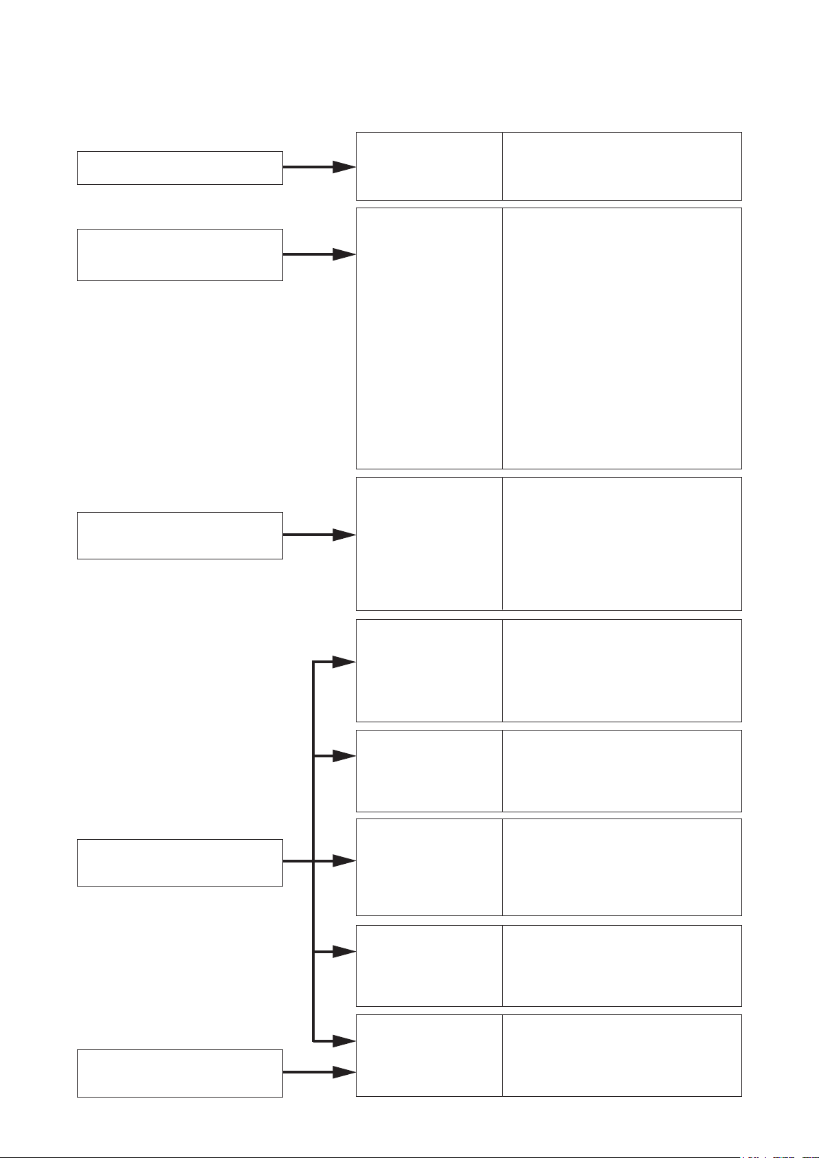
2. OPERATING INSTRUCTIONS CONFIGURATION
This operating instruction consists of Chapter 1 – 8 as follows.
Please read the necessary chapter as required.
To all users
To the person who operates
the equipment
To the person who installs and
wires the equipment
Chapter 1
General Description
Chapter 2
Function and
Operation
Chapter 3
Installation and
Wiring
• System Configuration
• Nomenclature and Functions
• System Function
• Master Station's Functions and
Operation
• Remote Microphone Station's
Fanctions and Operation
• Door Station's Functions and
Operation
•
Substation/Switch Panel's Functions
and Operation
• N-8000AL Telephone Interface
connected Telephone Functions
and Operation
• Operation from Outside Line
Telephone
• Other Functions (useful functions)
• Remarks (list of signal tones)
• Installation of the Exchange
• Installation of the Substation
Interface Unit
• Installation of the Various Kinds of
Interface Units
• Installation of Stations
• Wiring
To the person who designs
and maintains the system
To the person who installs and
wires the equipment
Chapter 4
System Design
Precautions
Chapter 5
System Settings by
Software
Chapter 6
System Settings
Using the Browser
Chapter 7
Multifunctional Station
Menu Screen Operation
(N-8000MS/8500MS only)
Chapter 8
Appendix
• Turning the System's Power
Switch ON
• Network Settings with a Personal
Computer
• System Setting Items and Default
• General Description
• Installation and Activating
• Equipment Scan
• System Settings
• Starting the Browser
• Network Settings
• Operating Status Indication,
Operation Log Indication
• System Administration
• Menu Items
• Entering Maintenance Screen
• Settings
•
• Trouble Occurs
•
• Specifications
Basic Knowledge about Networks
Indicator Status & Troubleshooting
17
Page 18

Chapter 1
GENERAL DESCRIPTION
This chapter describes the N-8000 Series Packet Intercom System's
basic equipment configurations (exchanges, stations and various
interface units), component functions and operations, and two types
of conversation methods.
Page 19

Chapter 1
GENERAL DESCRIPTION
1. GENERAL DESCRIPTION
The N-8000 Series is a packet intercom system (IP network compatible intercom) employing packet audio
technology*1. By connecting IP intercom exchanges (which can connect up to 16 stations per exchange),
IP stations, and various kinds of interface units to a network (LAN or WAN*2), an optimal system can be
constructed for in-house or wide area information communications such as duplex conversations between
stations, periodical broadcasts, and BGM broadcasts. Since up to 192 exchanges, IP stations, and various
kinds of interface units can be combined, systems of up to a total of 3072 stations can be realized. An echo
canceller*3 and voice switch realize hands-free conversation (conversations made without using a handset at
both parties) between stations. Depending on conditions, full duplex (simultaneous two-way) conversation by
way of an echo canceller or half duplex (alternate two-way) conversation by way of a voice switch is made.
(Refer to p. 8-2, "FULL DUPLEX AND HALF DUPLEX CONVERSATIONS.")
In addition, The system's various interface units and modules can be used to realize a host of functions,
including contact bridging by means of contact input and output control, contact external equipment control
and timer-activated fixed-time broadcasts, connection to outside lines (central office lines), and broadcast to the
SX-2000 system. Further, the system supports two different conversation methods and is capable of operating
in master/master or master/sub configurations.
*1 Technology related to audio transmission over a network
*2 The fixed global IP address must be assigned to the units connected via the Internet.
*3 A circuit that prevents acoustic feedback or echo generated when the voice output from the station's internal
speaker enters the microphone.
Warning
This is a class A product. In a domestic environment this product may cause radio interference in which case
the user may be required to take adequate measures.
1-2
Page 20

Chapter 1
GENERAL DESCRIPTION
2. FEATURES
• Exchanges,IPstations,andvariouskindsofinterfaceunitscanbeconnectedoveradatacommunications
network.
• Canbeconnectedtoanexistinglocalareanetwork(LAN)orwide-areanetwork(WAN).Thesystemcanalso
beeasilyconnectedtober-opticnetworkswithoutrestrictionsonoperatingdistance.
• Thededicatedsoftwareprogramenablescentralizedcontrolwithapersonalcomputer.
• Systemmaintenance(verifyingoperationlogandLinesupervision)canalsobeperformedwithapersonal
computer and Internet browser.
• 3typesofexchangesdifferinthefollowingpoints.
(1) 2-wire system
N-8000EX: Internal 4 links*, external 8 links*, with PA paging output
N-8010EX: Internal 1 link*, external 2 links*, without PA paging output
(2) 2-core shielded system
N-8000RS: External 2 links*
N-8010RS: External 1 link*
(3) 4-wire system
N-8400RS: External 2 links*
• 4typesofstationsareavailable:2-wiresystem,2-coreshieldedsystem,4-wiresystemandIP-typestations.
Therstthreestationsmustbeconnectedtoacorrespondingsystemexchangetomakeoperationpossible,
while the IP station can be operated on its own without being connected to any exchange. (However, the
systemconguredonlywithIPdoorstationscannotberealized.)
(1) IP - t yp e
(2) 2-wire system
(3) 2-core shielded system
(4) 4-wire system
• Therearevetypesofinterfaceunitsasshownbelow:
(1) Multi interface unit
(2) Audio interface unit
(3) Direct select unit
(4) C/O interface unit
(5) Telephone interface unit
• TheMultiinterfaceunitorDirectselectunitcaninterlockwithanelectroniclocksystemorCCTVsurveillance
system by way of contact input/output control function.
• UsingIPstationspermitsasystemhavingnoexchangetobecreated.However,thesystemconguredonly
with IP door stations cannot be realized.
• UsingIPinterfacemodulespermitsbroadcasttotheSX-2000system.
* Link is a speech path. The "internal 4 links" means that 4 simultaneous calls can be performed between the
stations connected to an exchange or 4 different broadcasts can be simultaneously made in a system. The
"external 8 links" means that 8 simultaneous calls can be made to the stations connected to other exchange
or to IP stations, or 8 different broadcasts can be simultaneously made to other exchange system.
3. HANDLING PRECAUTIONS
The Internet is not guaranteed quality. So, when this system is connected to the Internet, packet loss may result
if the network is congested, possibly causing voice communications to be interrupted or noise to be generated.
1-3
Page 21

4. SPECIFICATIONS
Chapter 1
GENERAL DESCRIPTION
Number of Units Connectable to LAN
(a total of Exchanges, IP stations, and various kinds of interface units)
Line Capacity: Maximum 3072 (192 Exchanges x 16 stations per Exchange)
Speech Link Capacity: Maximum 768 (192 N-8000EX Exchanges)
Single exchange
N-8000EX: 4 links
N-8010EX: 1 link
N-8400RS: 1 link
Unit to unit
N-8000EX: 8 links
N-8010EX: 2 links
N-8000RS: 2 links
N-8010RS: 1 link
N-8400RS: 2 links
N-8000MI: 2 links
Speech (through the PBX or tie-line): Maximum 2 links
Audio input: Maximum 2 links
Audio output: Maximum 2 links
Note
The above links can be simultaneously used.
(Refer to the table on p. 1-13.)
SX-200IP: 2 links
Paging
Paging zones: Maximum 192
Paging outputs: Maximum 384 ( When 192 N-8000EX Exchanges or Multi interface units
N-8000EX: 2 outputs
N-8000MI: 2 outputs
N-8000AF: 1 output
Simultaneous access capacity for paging links:
N-8000EX: Multicast paging: Maximum 4 links
Unicast paging: 1 link
N-8010EX: Multicast paging: Maximum 2 links
Unicast paging: 1 link
N-8000MI: Multicast paging: Maximum 2 links
Unicast paging: 1 link
N-8000AF: Multicast paging: Maximum 1 link
Unicast paging: 1 link
N-8500MS: Multicast paging: 1 link
Unicast paging: 1 link
N-8510MS: Multicast paging: 1 link
Unicast paging: 1 link
N-8600MS: Multicast paging: 1 link
Unicast paging: 1 link
N-8610RM: Multicast paging: 1 link
Unicast paging: 1 link
N-8000AL: Multicast paging: 1 link
Unicast paging: 1 link
N-8000CO: Multicast paging: 1 link
Unicast paging: 1 link
N-8400RS: Multicast paging: Maximum 2 links
Unicast paging: 1 link
SX-200IP: Multicast zone broadcast: 2 links
Unicast zone broadcast: 2 links
Paging destinations via network: Multicast paging: Maximum 191
Unicast paging: Maximum 16
(N-8000AL/8000AF/8000CO: Maximum8)
Zone broadcast to SX-2000 system: Maximum 16 basses per system
Maximum 128 basses (8 systems)
: Maximum 192
are connected)
1-4
Page 22

Chapter 1
BGM: Maximum 8 channels (Number of channels selectable at the station)
PBX Interface: Maximum 384 (When 192 Multi interface units are connected)
Tie-line Interface: Maximum 384 (When 192 Multi interface units are connected)
C/O Interface: Maximum 192 (When 192 C/O interface units are connected)
Telephone Interface: Maximum 384 (When 192 Telephone interface units are connected)
External Contact Output:
N-8000MI: Maximum 3072 (When 192 Multi interface units are connected)
N-8000DI: Maximum 6144 (When 192 Direct select units are connected)
N-8000AF: Maximum 1536 (When 192 Audio interface units are connected)
External Contact Input:
N-8000MI: Maximum 3072 (When 192 Multi interface units are connected)
N-8000DI: Maximum 6144 (When 192 Direct select units are connected)
N-8000AF: Maximum 1536 (When 192 Audio interface units are connected)
System Settings:
(Network Related)
Voice Delay Time: 80 or 320 ms, selectable
Connection Delay Time: Maximum 1 second (When Multicast paging is made to 191 zones)
Usage Bandwidth:
Maximum 130 kbps (two-way)/one call
Personal computer setting using a dedicated software program (over LAN)
Maximum 2.08 Mbps (one way)/When Unicast paging is made to 16 zones
GENERAL DESCRIPTION
1-5
Page 23
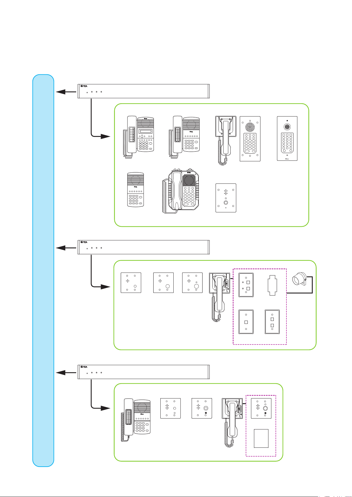
5. SYSTEM CONFIGURATION
5.1. System Configuration Example
This system consists of the following equipment.
2-wire type exchange N-8000EX/8010EX
2-wire type station
N-8000MS N-8010MS
Chapter 1
GENERAL DESCRIPTION
N-8031MS N-8033MSRS-191
Network
N-8020MS
2-core shielded type exchange N-8000RS/8010RS
2-core shielded type station
RS-150 RS-160/170
4-wire type exchange N-8400RS
4-wire type station
RS-180
N-8050DSN-8011MS
RS-140 RS-142
RS-141
RS-143 RS-144
N-8410MS
RS-450 RS-460/470
RS-481
RS-480
RS-442
1-6
Page 24
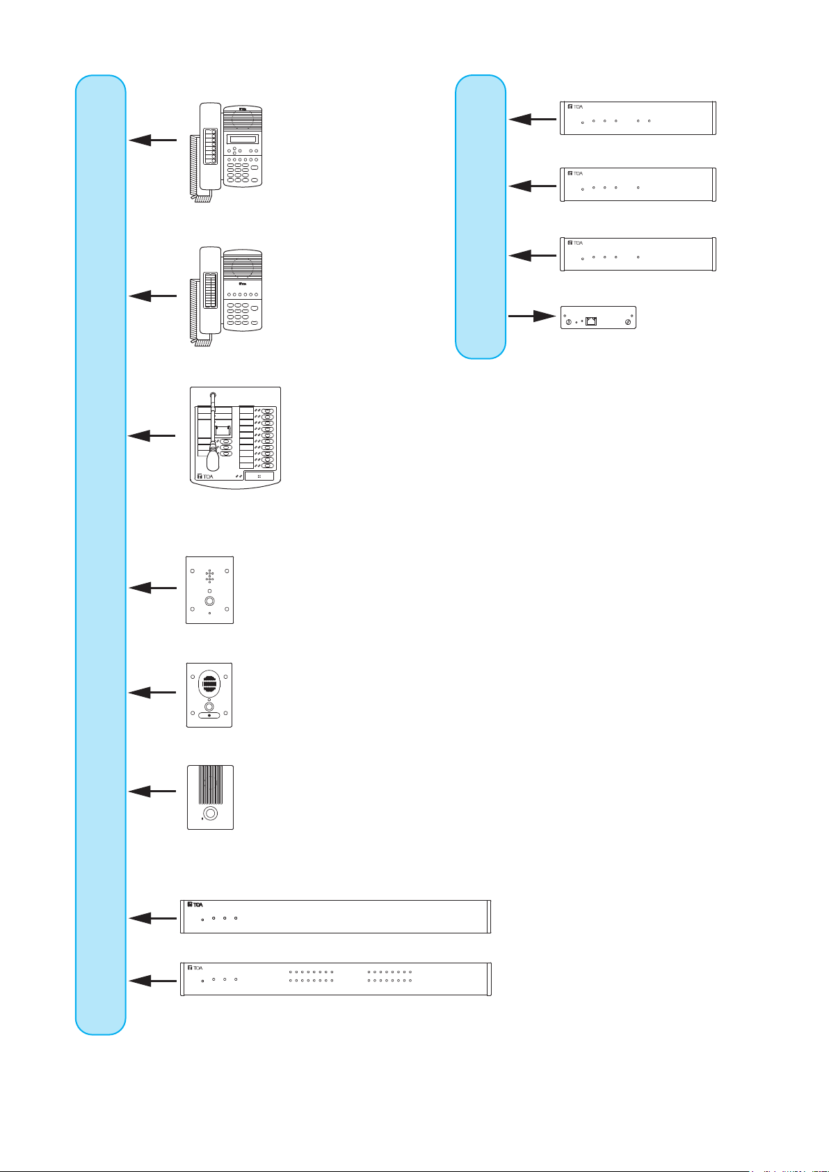
Chapter 1
GENERAL DESCRIPTION
IP type station
N-8500MS/8600MS
N-8510MS
Network
Audio interface unit N-8000AF
Telephone interface unit N-8000AL
C/O interface unit N-8000CO
IP interface module SX-200IP
Network
N-8610RM
N-8540DS
N-8640DS
N-8650DS
Multi interface unit N-8000MI
Direct select unit N-8000DI
1-7
Page 25

Chapter 1
GENERAL DESCRIPTION
5.1.1. Exchange
[2-wire type exchange]
N-8000EX: IP Intercom Exchange
N-8010EX: IP Intercom Exchange
[2-core shielded type exchange]
N-8000RS: Substation Interface Unit
N-8010RS: Substation Interface Unit
[4-wire type exchange]
N-8400RS: Substation Interface Unit
5.1.2. Stations
[IP stations]
N-8500MS: IP Multifunctional Master Station
N-8510MS: IP Standard Master Station
N-8600MS: IP Multifunctional Master Station
N-8610RM: IP Remote Microphone Station
N-8540DS: IP Door Station
N-8640DS: IP Door Station
N-8650DS: IP Door Station
[2-wire type stations]
N-8000MS: Multifunctional Master Station
N-8010MS: Standard Master Station
N-8011MS: Standard Hands-Free Master Station
N-8020MS: Industrial-Use Master Station
N-8031MS: Flush-Mount Master Station
N-8033MS: Flush-Mount Master Station
RS-191: Option Handset
N-8050DS: Door Station
[2-core shielded type stations]
RS-150: Substation
RS-160: Substation
RS-170: Substation
RS-180: Substation
RS-140: Switch Panel
RS-141: Option Handset for RS-140/142/143
/14 4
RS-142: Switch Board
RS-143: Switch Panel
RS-144: Switch Panel
5.1.3. Peripheral components
N-8000MI: Multi Interface Unit
N-8000DI: Direct Select Unit
N-8000AF: Audio Interface Unit
N-8000CO: C/O Interface Unit
N-8000AL: Telephone Interface Unit
SX-200IP: IP Interface Module
5.1.4. Others
YC-150: Back Box for the N-8050DS/8540DS/
8640DS/8650DS
YC-241 Back Box for the N-8031MS
YC-251: Wall-Mount Box for the N-8031MS
YC-280: Wall Mounting Bracket for the
N-8000MS/8010MS/8020MS/8410MS
/8500MS/8510MS/8600MS
YC-290: Wall Mounting Bracket for the
N- 8011M S
YC-302: 2-Gang Electrical Box
YC-801: Flush-Mount Box for the RS-140/143/
144
YC-802: Wall-Mount Box for the RS-140/143/
144
YC-822: Wall-Mount Box
YC-823: Wall-Mount Box
YC-841: Wall-Mount Box for the N-8033MS
YC-850: Interface Unit Bracket
(For N-8000RS/8010RS/8400RS
/8000DI/8000AF/8000CO/8000AL)
YS-13A: Wall-Mount Box for the
N-8050DS/8540DS/8640DS/8650DS
AD -1210 P:
8600MS/8540DS/8640DS/8650DS
AD -1215P:
8600MS/8540DS/8640DS/8650DS
E-7000TB: 40-Station Terminal Board
CR-273: Equipment Rack
CR-413: Equipment Rack
AC Adapter for the N-8500MS/8510MS/
AC Adapter for the N-8500MS/8510MS/
[4-wire type stations]
N-8410MS: Analog Standard Master Station
RS-442: Switch Board
RS-450: Substation
RS-460: Substation
RS-470: Substation
RS-480: Substation
RS-481: Option Handset for RS-480
1-8
Page 26

Chapter 1
GENERAL DESCRIPTION
5.2. Component Description
5.2.1. Exchange
[2-wire type exchange]
• N-8000EXIPIntercomExchange
The Exchange permits connection of up to sixteen 2-wire type stations and features two outputs for public
address paging. The speech links consist of 4 internal links and 8 external links. The exchange is equipped
with a networking interface, allowing connection with IP stations, various kinds of interface units, and other
IP intercom exchanges. The Exchange can be mounted in an EIA standard rack (1U), to a wall or installed on
a desk.
• N-8010EXIPIntercomExchange
The Exchange permits connection of up to sixteen 2-wire type stations.
The speech links consist of 1 internal link and 2 external links.
The exchange is equipped with a networking interface, allowing connection with IP stations, various kinds of
interface units, and other IP intercom exchanges.
The Exchange can be mounted in an EIA standard rack (1U), to a wall or installed on a desk.
[2-core shielded type exchange]
• N-8000RSIPIntercomSubstationInterfaceUnit
The Exchange permits connection of up to sixteen 2-core shielded type stations.
The speech links consist of 2 external links.
The exchange is equipped with a networking interface, allowing connection with IP stations, various kinds of
interface units, and other IP intercom exchanges.
The Exchange can be mounted in an EIA standard rack (1U), to a wall or installed on a desk.
• N-8010RSIPIntercomSubstationInterfaceUnit
The Exchange permits connection of up to sixteen 2-core shielded type stations.
The speech link consists of 1 external link.
The exchange is equipped with a networking interface, allowing connection with IP stations, various kinds of
interface units, and other IP intercom exchanges.
The Exchange can be mounted in an EIA standard rack (1U), to a wall or installed on a desk.
[4-wire type exchange]
• N-8400RSIPIntercomSubstationInterfaceUnit
The Exchange permits connection of up to sixteen 4-wire type stations.
The speech links consist of 1 internal link and 2 external links.
The exchange is equipped with a networking interface, allowing connection with IP stations, multi interface
units, and other IP intercom exchanges.
The Exchange can be mounted in an EIA standard rack (1U), to a wall or installed on a desk.
Kind of Exchange Model No.
2-wire type
exchange
2-core shielded
type exchange
4-wire type
exchange
N-8000EX
N-8010EX
N-8000RS
N-8010RS
N-8400RS
Communication methods Internal Link
Audio: Digital PCM
Control: Multiplex system
Audio: Analog base band
Control: Current loop system
Audio: Analog base band
Control: Current loop/pilot tone system
4
1
Impossible
1 2
External Link
8
2
2
1
1-9
Page 27

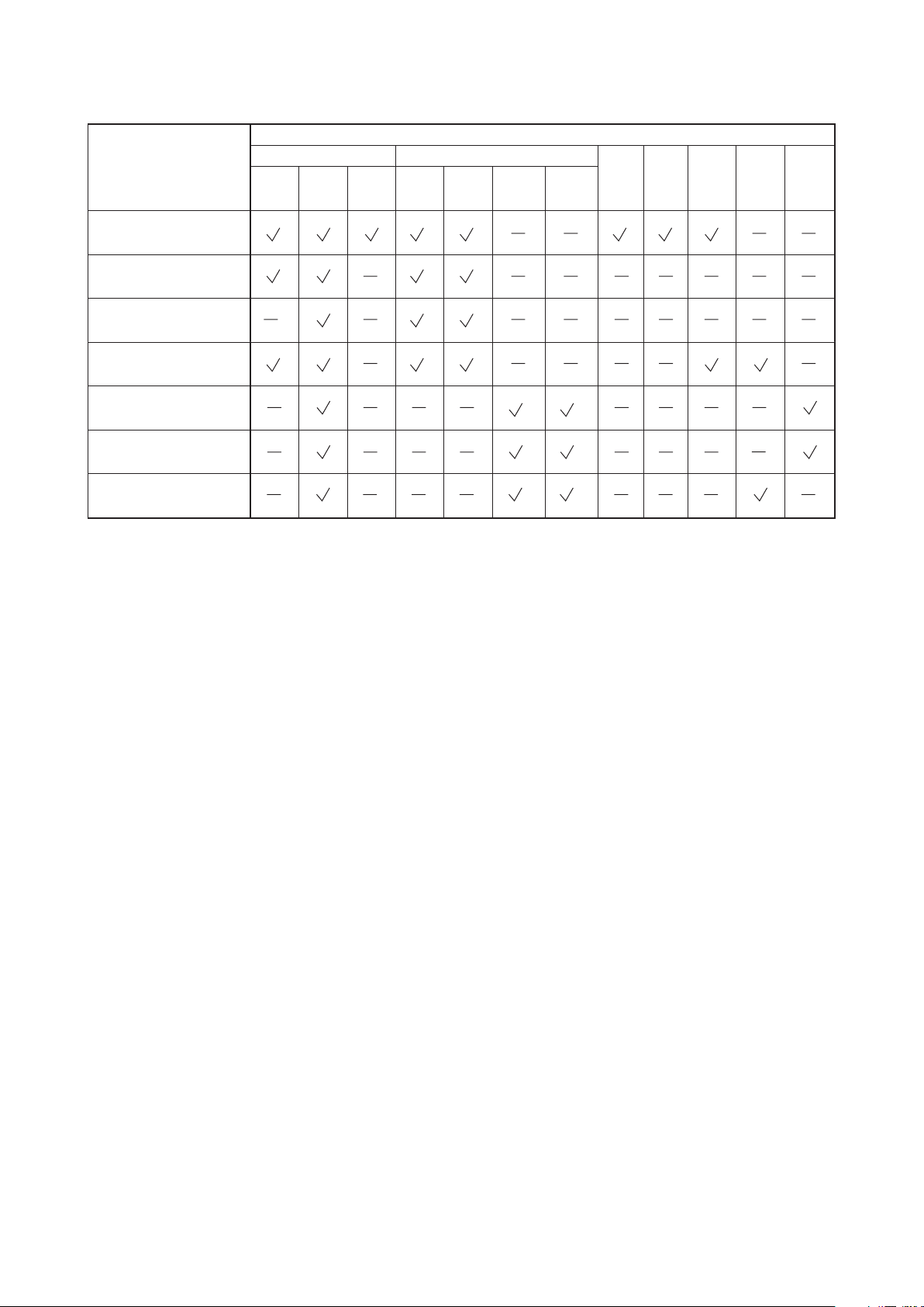
5.2.2. Stations
[IP station]
Type of Stations
Speech Method Installation Method
Handset
Handsfree
Headset Desk top
Wall
hanging
Flushmounting
Specification
Wall
surface
mounting
LCD
Display
Chapter 1
Auto-
External
dialing
speaker
GENERAL DESCRIPTION
Control
input
PC
cascadeconnection
Control
output
Power
N-8500MS:
IP Multifunctional
Master Station
N-8510MS:
Standard
Master Station
N-8600MS:
IP Multifunctional
Master Station
N-8610RM:
IP Remote
Microphone Station
N-8540DS:
IP Door Station
N-8640DS:
IP Door Station
N-8650DS:
IP Door Station
1
*
The front operation panel can be inclined 16° from the desk surface by attaching the YC-280 Wall Mounting
*1 *2
*1 *2
*1 *2
*4
*5 *6 *3
*5 *6 *3
*5 *6 *3
Bracket to its bottom surface.
*2 A dedicated YC-280 Wall Mounting Bracket is required.
*3 A PoE (Power over Ethernet) switching hub compliant with IEEE802.3af or optional AD-1210P/1215P AC
Adapter is required.
*4 A dedicated WB-RM200 Wall Mount Bracket is required.
*5 A dedicated YC-150 Back Box is required.
*6 A dedicated YS-13A Wall-Mount Box is required.
*3
*3
*3
*3
1-10
Page 28
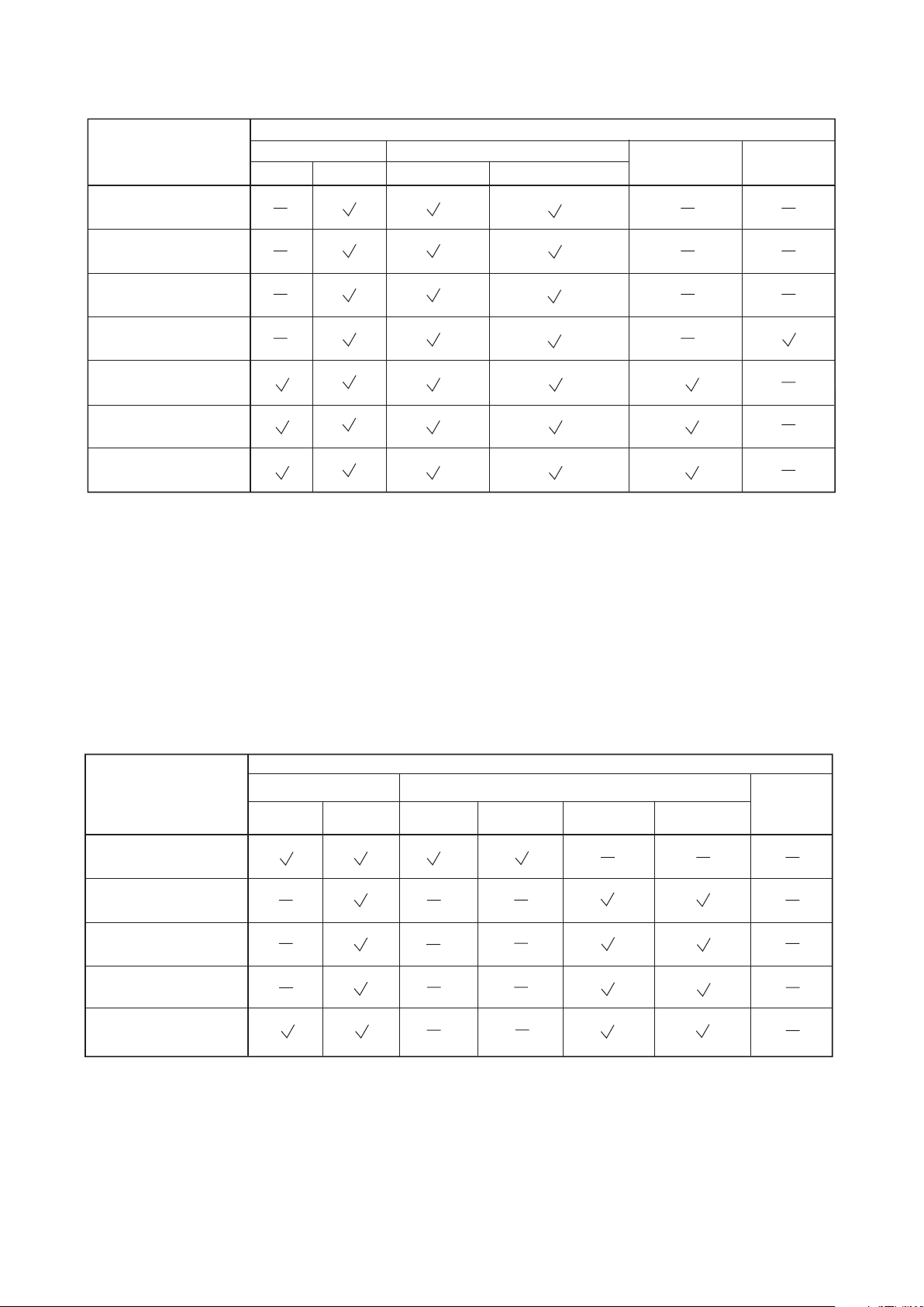
[2-wire type station]
Type of Stations
N-8000MS: Multifunctional
Master Station
N-8010MS: Standard
Master Station
Speech Method Installation Method
Handset
Handsfree
Headset
Desk top
*1
*1
Wall
hanging
*3
*3
Specification
Flushmounting
Chapter 1
Wall
surface
mounting
GENERAL DESCRIPTION
LCD
Display
Autodialing
External
speaker
Control
output
External
dial input
N-8011MS: Standard
Hands-Free Master Station
N-8020MS: Industrial-Use
Master Station
N-8031MS: Flush-Mount
Master Station
N-8033MS: Flush-Mount
Master Station
N-8050DS: Door Station
*2
*1
*5 *6
*4
*3
*8
*10
*7 *9
*10
*1 The front operation panel can be inclined 16° from the desk surface by attaching the YC-280 Wall Mounting
Bracket to its bottom surface.
*2 The front operation panel can be inclined 16° from the desk surface by attaching the YC-290 Wall Mounting
Bracket to its bottom surface.
*3 A dedicated YC-280 Wall Mounting Bracket is required.
*4 A dedicated YC-290 Wall Mounting Bracket is required.
*5 Permits handset conversation when used in conversation with the RS-191 Option Handset
*6 A dedicated YC-241 Back Box is required.
*7 A dedicated YC-150 Back Box is required.
*8 A dedicated YC-251 Wall-Mount Box is required.
*9 A dedicated YS-13A Wall-Mount Box is required.
*10 A dedicated YC-841 Wall-Mount Box is required.
1-11
Page 29
[2-core shielded station]
Type of Stations
RS-150:
Sub Station
RS-160:
Sub Station
Speech Method Installation Method
Handset Hands-free
Flush-mounting Wall surface mounting
*1
*1
Specification
*2
*2
Chapter 1
GENERAL DESCRIPTION
Control outputExternal speaker
RS-170:
Sub Station
RS-180:
Sub Station
RS-140:
Switch Panel
RS-143:
Switch Panel
RS-144:
Switch Panel
*1
*1
*4 *7 *5
*5
*5
*5
*6
*6*4 *7 *5
*6*4 *7 *5
*2, *3
*2, *3
*1 A dedicated YC-302 2-Gang Electrical Box is required.
*2 A dedicated YC-822 Wall-Mount Box is required.
*3 A dedicated YC-823 Wall-Mount Box is required.
*4 Permits handset conversation when used in conversation with the RS-141 Option Handset
*5 Connection to an already installed 25 V line speaker allows it to be used for conversation applications (as
it can be made to function both as a microphone and a speaker).
*6 A dedicated YC-801 Flush-Mount Box is required.
*7 A dedicated YC-802 Wall-Mount Box is required.
[4-wire type station]
Specification
Type of Stations
N-8410MS: Analog
Standard Master Station
RS-450:
Sub Station
RS-460:
Sub Station
RS-470:
Sub Station
RS-480:
Sub Station
1
The front operation panel can be inclined 16° from the desk surface by attaching the YC-280 Wall Mounting
*
Speech Method Installation Method
Handset Hands-free
*6
Desk
top
*1
Wall
hanging
*2
Flush-
mounting
*3
*3
*3
*3
Wall surface
mounting
*4
*4
*4, *5
*4, *5
Control
output
Bracket to its bottom surface.
*2 A dedicated YC-280 Wall Mounting Bracket is required.
*3 A dedicated YC-302 2-Gang Electrical Box is required.
*4 A dedicated YC-822 Wall-Mount Box is required.
*5 A dedicated YC-823 Wall-Mount Box is required.
*6 Permits handset conversation when used in conversation with the RS-481 Option Handset
1-12
Page 30

Chapter 1
GENERAL DESCRIPTION
5.2.3. Peripheral components
[N-8000MIMultiInterfaceUnit]
Having 2 channels each for audio input and output, and 16 contacts each for control input and output, the
N-8000MI performs the following interface functions*.
•Tie-lineinterfaceforconnectionwiththeEXES-2000andEXES-6000systems.
•PBXinterfaceforconnectionwiththePBXviatheanalogE&Minterface.
•PApaginginterfaceforconnectionwithPAequipment
•Externalinputbroadcastinterfaceforconnectionwithamusicplayer(chimeunit)orpagingmicrophone
irrespective of with or without remote control function.
•Interfacefunction thatenables external broadcast byconnectinga paging microphone ora playing
device without a Remote Control function.
•InterfacetocontrolanindicatororexternalequipmentsuchasaCCTV'sswitcherusingrelaycontacts.
•Interfacefunction that enables CallingStation Displayand RemoteDialingfunctions for designated
Master Stations using contact input and output.
•Interfacefunctionthatusescontactoutputtodiagnosesystemlineandnetworkstatusesandtransmits
the diagnosed result.
The N-8000MI also features Network interface for connection with IP stations, IP intercom exchanges, and
various kinds of interface units.
The N-8000MI interface is a rack-mounted model (1U size), but can be used for desktop and wall-mount
applications as well.
* The interface functions can be combined in the following 9 patterns.
Interface function
PBX 1
PBX 2
Tie-line 1
Tie-line 2
Audio output 1
Audio output 2
Audio input 1
Audio input 2
Contact IN/OUT
1 23456789
Combination pattern
[N-8000AFAudioInterfaceUnit]
Having 1 channel for audio input and output, and 8 contacts each for control input and output, and 1 contact for
time sync input , the N-8000AF performs the following interface functions.
• PApaginginterfaceforconnectionwithPAequipment
• Externalinputbroadcastinterfaceforconnectionwithamusicplayer(chimeunit)orpagingmicrophone
irrespective of with or without remote control function.
• Interfacefunctionthat enablesexternal broadcastby connecting apagingmicrophone or aplaying
device without a Remote Control function.
• TheTimeSignalfunctionenablestheN-8000AFtoactivateitsbuilt-intimeratpresettimestoplayits
built-in sound source or an external playing device by closing the contact output terminal.
• TheInterfacefunctionrecordsthedesignatedMasterStation'sconversationonanexternalrecorder
by outputting the conversation from the N-8000AF's audio output and transmitting it to the recorder
activated when the N-8000AF's contact output terminal is closed.
• NTP Clientfunction synchronizestheclockofthe N-8000AFwithNTPserverwhen the NTPClient
function of the N-8000AF set to the clock master is enabled.
The N-8000AF also features Network interface for connection with IP stations, IP intercom exchanges, and
various kinds of interface units.
The N-8000AF is a rack-mounted model (1U size and half-size width), but can be used for desktop and wallmount applications as well.
1-13
Page 31

Chapter 1
[N-8000DIDirectSelectUnit]
Having 32 contacts each for control input and output, the N-8000DI performs the following interface functions.
•InterfacetocontrolanindicatororexternalequipmentsuchasaCCTV'sswitcherusingrelaycontacts.
•InterfacefunctionthatenablesDirectSelect,CallingStationDisplayandRemoteDialingfunctionsfor
designated Master Stations using contact input and output.
•Interfacefunctionthatusescontactoutputtodiagnosesystemlineandnetworkstatusesandtransmits
the diagnosed result.
The N-8000DI also features Network interface for connection with IP stations, IP intercom exchanges, and
various kinds of interface units.
The N-8000DI is a rack-mounted model (1U size), but can be used for desktop and wall-mount applications as
well.
[N-8000COC/OInterfaceUnit]
This unit has one analog outside line circuit and connects to the outside line to enable the following functions:
•DirectInLine—CallsthedesignatedMasterStationfromtheanalogoutsideline.
•DirectInwardDialing—CallstheMasterStationfromtheanalogoutsidelinebydesignatingthatstation
through dialing.
•OutsideLineCallTransfer—TransferscallstotheanalogoutsidelinewhenthecalledMasterStation
is not available or does not respond.
•OutsideLinePaging—Makespagingcallsfromtheanalogoutsideline.
•Outside Line Equipment Control — Controls external equipment connected to the N-8000MI or
N-8000DI from the analog outside line.
GENERAL DESCRIPTION
The N-8000CO also features Network interface for connection with IP stations, IP intercom exchanges, and
various kinds of interface units.
The N-8000CO is a rack-mounted model (1U size and half-size width), but can be used for desktop and wallmount applications as well.
[N-8000ALTelephoneInterfaceUnit]
The N-8000AL unit has one outside line connection circuit and connects to analog telephones to enable the
following functions:
•Master Station — Permits the connected analog telephone to be used in the same manner as the
Master Station.
The N-8000AL also features Network interface for connection with IP stations, IP intercom exchanges, and
various kinds of interface units.
The N-8000AL is a rack-mounted model (1U size and half-size width), but can be used for desktop and wallmount applications as well.
[SX-200IPIPInterfaceModule]
The SX-200IP is a module to enable broadcasts from the N-8000 system to the SX-2000 system. Incorporated
in the SX-2100AI Audio input unit of the SX-2000 system, the SX-200IP allows broadcasts from the N-8600MS
Multifunctional master station or N-8610RM IP Remote microphone station to be made to each zone of the SX2000 system.
5.2.4. Others
[40-StationTerminalBoardE-7000TB]
The E-7000TB is a clip type terminal board for connecting station lines to each exchange. Up to 40 lines
(twisted pair cables) can be connected. The optional YC-105 clipping tool is required for wiring. The E-7000TB
is rack-mountable (3U size).
[EquipmentRacksCR-273andCR-413]
The Exchange, 40-station terminal board, and other equipment components are mounted in these racks.
1-14
Page 32

Chapter 1
Blower unit
GENERAL DESCRIPTION
5.3. Rack Mounting Examples for Exchanges
Note
The Exchange N-8000EX in these examples can be replaced with the N-8010EX/8000RS/8010RS/8400RS.
5.3.1.A128-lineexchangesystem
One CR-273 Equipment Rack is
used.
Blower unit
(BU-412)
Terminal board
(E-7000TB)
Terminal board
(E-7000TB)
Terminal board
(E-7000TB)
Terminal board
(E-7000TB)
Exchange (N-8000EX)
Exchange (N-8000EX)
Perforated panel
Exchange (N-8000EX)
Exchange (N-8000EX)
Perforated panel
Exchange (N-8000EX)
Exchange (N-8000EX)
Perforated panel
Exchange (N-8000EX)
Exchange (N-8000EX)
Perforated panel
Switching hub
Power distributor
5.3.2. A 192-line exchange system
One CR-413 Equipment Rack is
used.
(BU-412)
Terminal board
(E-7000TB)
Terminal board
(E-7000TB)
Terminal board
(E-7000TB)
Terminal board
(E-7000TB)
Terminal board
(E-7000TB)
Terminal board
(E-7000TB)
Exchange (N-8000EX)
Exchange (N-8000EX)
Perforated panel
Exchange (N-8000EX)
Exchange (N-8000EX)
Perforated panel
Exchange (N-8000EX)
Exchange (N-8000EX)
Perforated panel
Exchange (N-8000EX)
Exchange (N-8000EX)
Perforated panel
Exchange (N-8000EX)
Exchange (N-8000EX)
Perforated panel
Exchange (N-8000EX)
Exchange (N-8000EX)
Perforated panel
Switching hub
Power distributor
Power distributor
Perforated panel
Exchange (N-8000EX)
Exchange (N-8000EX)
Perforated panel
Exchange (N-8000EX)
Exchange (N-8000EX)
Perforated panel
Exchange (N-8000EX)
Exchange (N-8000EX)
Perforated panel
Exchange (N-8000EX)
Exchange (N-8000EX)
Perforated panel
Exchange (N-8000EX)
Exchange (N-8000EX)
Perforated panel
Exchange (N-8000EX)
Exchange (N-8000EX)
Perforated panel
Exchange (N-8000EX)
Exchange (N-8000EX)
Perforated panel
Power distributor
Power distributor
5.3.3. A 256-line exchange system
Two CR-273 Equipment Racks are
used.
Blower unit
(BU-412)
Perforated panel
Exchange (N-8000EX)
Exchange (N-8000EX)
Terminal board
(E-7000TB)
Terminal board
(E-7000TB)
Terminal board
(E-7000TB)
Terminal board
(E-7000TB)
Terminal board
(E-7000TB)
Terminal board
(E-7000TB)
Switching hub
Terminal board
(E-7000TB)
Terminal board
(E-7000TB)
256-line exchange (CR-273)128-line exchange (CR-273) 192-line exchange (CR-413)
1-15
Page 33

Chapter 1
Blower unit
GENERAL DESCRIPTION
5.3.4.A3072-lineexchangesystem
Sixteen CR-413 Equipment Racks are used.
(BU-412)
Rack No. 1 No. 8 No. 9 No. 15 No. 16
Exchange (N-8000EX)
Exchange (N-8000EX)
Perforated panel
Exchange (N-8000EX)
Exchange (N-8000EX)
Perforated panel
Exchange (N-8000EX)
Exchange (N-8000EX)
Perforated panel
Exchange (N-8000EX)
Exchange (N-8000EX)
Perforated panel
Exchange (N-8000EX)
Exchange (N-8000EX)
Perforated panel
Exchange (N-8000EX)
Exchange (N-8000EX)
Perforated panel
Exchange (N-8000EX)
Exchange (N-8000EX)
Perforated panel
Exchange (N-8000EX)
Exchange (N-8000EX)
Perforated panel
Exchange (N-8000EX)
Exchange (N-8000EX)
Perforated panel
Exchange (N-8000EX)
Exchange (N-8000EX)
Perforated panel
Exchange (N-8000EX)
Exchange (N-8000EX)
Perforated panel
Exchange (N-8000EX)
Exchange (N-8000EX)
Perforated panel
Switching hub
Power distributor
Power distributor
Exchange (N-8000EX)
Exchange (N-8000EX)
Perforated panel
Exchange (N-8000EX)
Exchange (N-8000EX)
Perforated panel
Exchange (N-8000EX)
Exchange (N-8000EX)
Perforated panel
Exchange (N-8000EX)
Exchange (N-8000EX)
Perforated panel
Exchange (N-8000EX)
Exchange (N-8000EX)
Perforated panel
Exchange (N-8000EX)
Exchange (N-8000EX)
Perforated panel
Exchange (N-8000EX)
Exchange (N-8000EX)
Perforated panel
Exchange (N-8000EX)
Exchange (N-8000EX)
Perforated panel
Exchange (N-8000EX)
Exchange (N-8000EX)
Perforated panel
Exchange (N-8000EX)
Exchange (N-8000EX)
Perforated panel
Exchange (N-8000EX)
Exchange (N-8000EX)
Perforated panel
Exchange (N-8000EX)
Exchange (N-8000EX)
Perforated panel
Switching hub
Power distributor
Power distributor
Blank panel (2U)
Terminal board
(E-7000TB)
Terminal board
(E-7000TB)
Terminal board
(E-7000TB)
Terminal board
(E-7000TB)
Terminal board
(E-7000TB)
Terminal board
(E-7000TB)
Terminal board
(E-7000TB)
Terminal board
(E-7000TB)
Terminal board
(E-7000TB)
Terminal board
(E-7000TB)
Terminal board
(E-7000TB)
Terminal board
(E-7000TB)
Terminal board
(E-7000TB)
Blank panel (2U)
Blank panel (3U)
Blank panel (3U)
Terminal board
(E-7000TB)
Terminal board
(E-7000TB)
Terminal board
(E-7000TB)
Terminal board
(E-7000TB)
Terminal board
(E-7000TB)
Terminal board
(E-7000TB)
Terminal board
(E-7000TB)
Terminal board
(E-7000TB)
Terminal board
(E-7000TB)
Terminal board
(E-7000TB)
Terminal board
(E-7000TB)
3072-line exchange (CR-413)
1-16
Page 34

Chapter 1
1 2 3 4
5
6. NOMENCLATURE AND FUNCTIONS
6.1. IP Intercom Exchanges and Their Connected Equipment
6.1.1.N-8000EXIPIntercomExchange
[Front]
GENERAL DESCRIPTION
1. Reset key [RESET]
Pressing this key reactivates the exchange.
2.LNK/ACTindicator[LNK /ACT](green)
Lightswhen connectedto a network,and ashes
while transmitting or receiving data.
3.Statusindicator[STATUS](red)
Continuously lights while data is written to an
internal storage medium (FlashMemory), and
ashestoindicatesuchexchangemalfunctionsas
cooling fan failure. (Refer to p. 8-14.)
[Rear]
4.Powerindicator[POWER](green)
Lights when power is supplied to the exchange.
5. MAC address
This is the MAC address* for the unit. Since the
relationship of each unit location to its MAC address
is established when setting the network attributes,
keep track of this relationship for later use.
* The inherent address assigned to each network
component, expressed in 12-digit hexadecimal
notation.
6 7 8 9 10 11 12
6. Functional earth terminal [SIGNAL GND]
Ground this terminal.
Note: This terminal is not for protective earth.
7.Coolingfan
CAUTION
Do not block the fan exhaust vent. Doing so
may cause heat to build up inside the unit and
result in fire.
8.ACinlet
Connect the supplied power cord.
Note
If there is a danger of lightning strikes, insert an
appropriate surge arrester into the power line.
9. Cord clamp
Pass the power cord through this clamp to ensure
that the plug does not pull out when the unit is
mounted to a wall. (Refer to p. 3-4.)
10.Lineconnectionterminals[LINE]
Connect the station to each terminal using a miniclamp connector. (Refer to p. 3-83, "Mini-clamp
connector connection.")
11.Paging output terminals [PAGING OUT 1/2,
AUDIO/CONTROL]
Includesaudiooutputs (0dB*,600Ω,balanced)
and contact outputs (no-voltage make, 24 V DC,
0.5 A MAX).
Each control output remains closed during audio
signal output.
Connect using a removable terminal plug. (Refer
to p. 3-83, "Terminal plug connection.")
12.Networkconnectionterminal[10/100M]
Connects a 10BASE-T- or 100BASE-TX-compatible
network. (Ethernet RJ-45 jack)
* 0 dB = 1 V
1-17
Page 35

6.1.2.N-8010EXIPIntercomExchange
1 2 3 4
5
[Front]
Chapter 1
GENERAL DESCRIPTION
1. Reset key [RESET]
Pressing this key reactivates the exchange.
2.LNK/ACTindicator[LNK /ACT](green)
Lightswhen connectedto a network,and ashes
while transmitting or receiving data.
3.Statusindicator[STATUS](red)
Continuously lights while data is written to an
internal storage medium (FlashMemory), and
ashestoindicatesuchexchangemalfunctionsas
cooling fan failure. (Refer to p. 8-14.)
[Rear]
4.Powerindicator[POWER](green)
Lights when power is supplied to the exchange.
5. MAC address
This is the MAC address* for the unit. Since the
relationship of each unit location to its MAC address
is established when setting the network attributes,
keep track of this relationship for later use.
* The inherent address assigned to each network
component, expressed in 12-digit hexadecimal
notation.
6 7 8 9 10 11
6. Functional earth terminal [SIGNAL GND]
Ground this terminal.
Note: This terminal is not for protective earth.
7.Coolingfan
CAUTION
Do not block the fan exhaust vent. Doing so
may cause heat to build up inside the unit and
result in fire.
8.ACinlet
Connect the supplied power cord.
Note
If there is a danger of lightning strikes, insert an
appropriate surge arrester into the power line.
9. Cord clamp
Pass the power cord through this clamp to ensure
that the plug does not pull out when the unit is
mounted to a wall. (Refer to p. 3-4.)
10.Lineconnectionterminals[LINE]
Connect the station to each terminal using a miniclamp connector. (Refer to p. 3-83, "Mini-clamp
connector connection.")
11.Networkconnectionterminal[10/100M]
Connects a 10BASE-T- or 100BASE-TX-compatible
network. (Ethernet RJ-45 jack)
1-18
Page 36

6.1.3.N-8000MSMultifunctionalMasterStation
[Top]
1
2
3
Chapter 1
GENERAL DESCRIPTION
4
5
6
7
8
9
10
11
12
1. Handset
Lift the handset for handset conversation. Lifting
the handset disconnects both the hands-free
microphone and the speaker.
2. Auto-dial key
Used to call or register the party to be called. (Refer
to p. 2 -11.)
3. Auto-dial directory
Writes the auto-dial registration contents to this
directory.
13
14
15 16 1817
5. Speaker
Outputs call tones and used for hands-free
conversations.
6. Liquid crystal display
Displays the dialed number or the number of a call
received in 2 lines of 16 digits. Pressing the Menu
key (8) displays the menu screen.
7.Selectionkey[SELECT]
Used for menu item selection or input value
conrmation.
4.Statusindicator(red)
Flashes when a call is received, continuously lights
during a conversation, and is off while in standby
mode. The indicator also continuously lights while
receiving a paging announcement.
8.Menukey[MENU]
Used for auto-dial registration (refer to p. 2-11) or
system settings. (Refer to Chapter 7.)
1-19
Page 37

Chapter 1
GENERAL DESCRIPTION
9. Redial key [REDIAL]
Permits the last called number to be dialed. (Refer
to p. 2-8.)
10.Functionkey[FUNCTION]
Use this key to perform function settings such as
assigning call transfer recipients or programming
one-touch dialing.
11. Push-to-talk key [PTT]
Pressing this key while calling a party by means
of a continuous call tone permits a voice call to
be made. (Refer to p. 2-9.) Also, pressing this
key during a hands-free conversation establishes
a one-way conversation from the party who
pressed the key. (Refer to p. 2-7.)
12. Dial keys
Use these keys to make a call or set a function.
13. Clear key [C]
Terminates the conversation.
14. Arrow keys [
Use these keys to perform auto-dial registration
(refer to p. 2 -11) or system settings (refer to
Chapter 7).
15. Paging key [CALL]
Makes a paging. (Refer to p. 2-25.)
16. Paging response key [RESP.]
Responds to a paging.
(Refer to p. 2-31.)
17.Holdkey[HOLD]
Places the conversation on hold.
(Refer to p. 2-14.)
18.Transferkey[TRANSFER]
Used to transfer the current conversation to
another station. (Refer to p. 2-15.)
][ ][ ][ ]
[Rear]
19
19.Externalspeakerterminal[EXT.SP.]
Anexternalspeaker(8Ω,0.6W)canbeconnected
to this terminal. (Refer to p. 3-57.)
Shift the Speaker selector switch (22) located
on the bottom surface of the unit to the EXT.SP
position when using the external speaker.
20.Headsetterminal[HEADSET]
Connects to a headset. Connection of the headset
disables the speaker.
2120
21. Line connection terminal [LINE]
Connects to the exchange. (RJ-11 modular jack)
1-20
Page 38

[Bottom]
22
23
Chapter 1
GENERAL DESCRIPTION
24
22.Speakerselectorswitch[INT.SP/EXT.SP]
Used to select either an internal (INT.SP) or an
external (EXT.SP) speaker.
23. Microphone
Used for hands-free conversation.
Note
Avoid placing obstacles close to the microphone
that might block sound and prevent conversations.
24.Wallbracketmountingslots
Hang the mounting bracket hooks to these slots
when using the YC-280 Wall Mounting Bracket.
(Refer to p. 3-19, p. 3-23.)
1-21
Page 39

6.1.4.N-8010MSStandardMasterStation
[Top]
1
Chapter 1
GENERAL DESCRIPTION
3
2
1. Handset
Lift the handset for handset conversation. Lifting
the handset disconnects both the hands-free
microphone and the speaker.
2. Dial directory
Writes the dial registration of the party to be called
to this directory.
3.Statusindicator(red)
Flashes when a call is received, continuously lights
during a conversation, and is off while in standby
mode. The indicator also continuously lights while
receiving a paging announcement.
4
5
6
7
8
9
10
11 12 13
7.Transferkey[TRANSFER]
Used to transfer the current conversation to
another station. (Refer to p. 2-15.)
8.Push-to-talkkey[PTT]
Pressing this key while calling a party by means
of a continuous call tone permits a voice call to
be made. (Refer to p. 2-9.) Also, pressing this
key during a hands-free conversation establishes
a one-way conversation from the party who
pressed the key. (Refer to p. 2-7.)
9. Dial keys
Use these keys to make a call or set a function.
4. Speaker
Outputs call tones and used for hands-free
conversations.
5. Function key [FUNCTION]
Use this key to perform function settings such as
assigning call transfer recipients or programming
one-touch dialing.
6. Redial key [REDIAL]
Permits the last called number to be dialed. (Refer
to p. 2-8.)
10.Clearkey[C]
Terminates the conversation.
11. Paging key [CALL]
Makes a paging. (Refer to p. 2-25.)
12. Paging response key [RESP.]
Responds to a paging.
(Refer to p. 2-31.)
13. Hold key [HOLD]
Places the conversation on hold.
(Refer to p. 2-14.)
1-22
Page 40

[Rear]
14. Line connection terminal [LINE]
Connects to the exchange. (RJ-11 modular jack)
[Bottom]
Chapter 1
GENERAL DESCRIPTION
14
15
15. Microphone
Used for hands-free conversation.
Note
Avoid placing obstacles close to the microphone
that might block sound and prevent conversations.
16
16.Wallbracketmountingslots
Hang the hooks of the mounting bracket to these
slots when using the YC-280 Wall Mounting
Bracket. (Refer to p. 3-19, p. 3-23.)
1-23
Page 41

4
6.1.5.N-8011MSStandardHands-freeMasterStation
[Top]
Chapter 1
5
GENERAL DESCRIPTION
1
2
3
1. Paging response key [RESP.]
Responds to a paging. (Refer to p. 2-31.)
2. Paging key [CALL]
Makes a paging. (Refer to p. 2-25.)
3. Hold key [HOLD]
Places the conversation on hold.
(Refer to p. 2-14.)
4.Statusindicator(red)
Flashes when a call is received, continuously lights
during a conversation, and is off while in standby
mode. The indicator also continuously lights while
receiving a paging announcement.
6
7
8
9
10
11
7.Redialkey[REDIAL]
Permits the last called number to be dialed. (Refer
to p. 2-8.)
8.Transferkey[TRANSFER]
Used to transfer the current conversation to
another station. (Refer to p. 2-15.)
9. Push-to-talk key [PTT]
Pressing this key while calling a party by means
of a continuous call tone permits a voice call to
be made. (Refer to p. 2-9.) Also, pressing this
key during a hands-free conversation establishes
a one-way conversation from the party who
pressed the key. (Refer to p. 2-7.)
5. Speaker
Outputs call tones and used for hands-free
conversations.
6. Function key [FUNCTION]
Use this key to perform function settings such as
assigning call transfer recipients or programming
one-touch dialing.
10.Dialkeys
Use these keys to make a call or set a function.
11. Clear key [C]
Terminates the conversation.
1-24
Page 42

[Rear]
12. Line connection terminal [LINE]
Connects to the exchange. (RJ-11 modular jack)
[Bottom]
Chapter 1
GENERAL DESCRIPTION
12
13
13. Microphone
Used for hands-free conversation.
Note
Avoid placing obstacles close to the microphone
that might block sound and prevent conversations.
14
14.Wallbracketmountingslots
Hang the mounting bracket hooks to these slots
when using the YC-290 Wall mounting bracket.
(Refer to p. 3-21, p. 3-22.)
1-25
Page 43

6.1.6.N-8020MSIndustrial-UseMasterStation
[Top]
Chapter 1
GENERAL DESCRIPTION
1
2
3
4
5
6
7
8
9
11 12
10
1. Handset
Lift the handset for handset conversation. Lifting
the handset disconnects both the hands-free
microphone and the speaker.
2.Statusindicator(red)
Flashes when a call is received, continuously lights
during a conversation, and is off while in standby
mode. The indicator also continuously lights while
receiving a paging announcement.
3. Speaker
Outputs call tones and used for hands-free
conversations.
4. Paging key [CALL]
Makes a paging. (Refer to p. 2-25.)
5. Paging response key [RESP.]
Responds to a paging. (Refer to p. 2-31.)
6. Function key [FUNCTION]
Use this key to perform function settings such as
assigning call transfer recipients or programming
one-touch dialing.
7.Redialkey[REDIAL]
Permits the last called number to be dialed. (Refer
to p. 2-8.)
8.Transferkey[TRANSFER]
Used to transfer the current conversation to
another station. (Refer to p. 2-15.)
9. Dial keys
Use these keys to make a call or set a function.
10.Holdkey[HOLD]
Places the conversation on hold.
(Refer to p. 2-14.)
11. Push-to-talk key [PTT]
Pressing this key while calling a party by means
of a continuous call tone permits a voice call to
be made. (Refer to p. 2-9.) Also, pressing this
key during a hands-free conversation establishes
a one-way conversation from the party who
pressed the key. (Refer to p. 2-7.)
12. Clear key [C]
Terminates the conversation.
1-26
Page 44

[Rear]
Protection cover
Chapter 1
GENERAL DESCRIPTION
13
13.Lineconnectioncable[LINE]
Connects to the exchange. (3 m-length cable with
RJ-11 modular plug)
Note: Do not remove the protection cover.
14.Externalspeakerterminal[EXT.SP.]
An external speaker (8 Ω, 0.6 W) can be
connected to this terminal. When connecting,
replace a protection cap with a supplied rubber
bushing. (Refer to p. 3-57.)
[Bottom]
Figure of the terminal
where protection cover
is removed
14 15
Shift the Speaker selector switch (16) located
on the bottom surface of the unit to the EXT.SP
position when using the external speaker.
15. Contact output terminal [CONTACT OUT]
Permits connection of a device to indicate the
calling station.
This terminal closes only while a call is being
made or received. (Output capacity: 30 V DC and
50 mA.)
When connecting, replace a protection cap with a
supplied rubber bushing. (Refer to p. 3-57.)
16
17
Figure viewed from front center
16.Speakerselectorswitch[INT.SP/EXT.SP]
The internal switch is exposed if the protection
cover is removed.
Used to select either an internal (INT.SP) or an
external (EXT.SP) speaker. After shifting the
selectorswitch,ttheprotectioncoverbackinto
place.
17.Microphone
Used for hands-free conversation.
18
Note
Avoid placing obstacles close to the microphone
that might block sound and prevent conversations.
18.Wallbracketmountingslots
Hang the mounting bracket hooks to these slots
when using the YC-280 Wall mounting bracket.
(Refer to p. 3-19, p. 3-23.)
1-27
Page 45

6.1.7.N-8031MSFlush-MountMasterStation
Chapter 1
[Rear][Front]
GENERAL DESCRIPTION
1
12
5
13
14
6
2
3
7
8
9
10
7
15
4
11
COM
8
9
C
12
1.Statusindicator(red)
Flashes when a call is received, continuously lights
during a conversation, and is off while in standby
mode. The indicator also continuously lights while
receiving a paging announcement.
2. Paging key [CALL]
Makes a paging. (Refer to p. 2-25.)
3. Hold key [HOLD]
Places the conversation on hold. (Refer to p. 2-14.)
4. Push-to-talk key [PTT]
Pressing this key while calling a party by means
of a continuous call tone permits a voice call to be
made. (Refer to p. 2-9.) Also, pressing this key
during a hands-free conversation establishes a
one-way conversation from the party who pressed
the key.
(Refer to p. 2-7.)
5. Speaker
Outputs call tones and used for hands-free
conversations.
6. Paging response key. [RESP.]
Responds to a paging. (Refer to p. 2-31.)
7.Functionkey[FUNCTION]
Use this key to perform function settings such as
assigning call transfer recipients or programming
one-touch dialing.
8.Redialkey[REDIAL]
Permits the last called number to be dialed. (Refer
to p. 2-8.)
9. Transfer key [TRANSFER]
Used to transfer the current conversation to
another station. (Refer to p. 2-15.)
10.Dialkeys
Use these keys to make a call or set a function.
11. Clear key [C]
Terminates the conversation.
12. Microphon e
Used for hands-free conversation.
13.Lineconnectionterminals[1,2]
Connect to the exchange. (Pin header)
Note
The removable terminal plug (2P) is factoryattached. (Refer to p. 3-56.)
1-28
Page 46

Chapter 1
GENERAL DESCRIPTION
14.Handsetconnectionterminals[CN302]
A dedicated RS-191 Option Handset can be
connected. (Refer to p. 3-58.)
6.1.8.RS-191IndoorOptionHandset
[Front]
15.Externaldialinputterminals[CN306]
An external switch such as a footswitch can be
connected. (Refer to p. 3-59.)
One-touch dial function needs be programmed
when using the external switch. (Refer to p. 2-12 .)
1.HandsetCable
Connects to the N-8031MS station's handset
connection terminal.
2. Handset
1
Used to make handset calls from the N-8031MS
station. While this handset is used, the N-8031MS
station's hands-free microphone and speaker are
cut off.
2
1-29
Page 47

6.1.9.N-8033MSFlush-MountMasterStation
Chapter 1
[Rear][Front]
GENERAL DESCRIPTION
1
12
13
5
6
2
3
7
8
9
10
7
14
4
11
COM
8
9
C
12
Note
The front protective sheet is a wear-and-tear item. It is highly recommended to replace it every 100,000 times
of operations (approx. 3 years) for any key.
Part code: 115-51-304-00
For replacement, please contact your nearest TOA dealer.
1.Statusindicator(red)
Flashes when a call is received, continuously lights
during a conversation, and is off while in standby
mode. The indicator also continuously lights while
receiving a paging announcement.
2. Paging key [CALL]
Makes a paging. (Refer to p. 2-25.)
3. Hold key [HOLD]
Places the conversation on hold. (Refer to p. 2-14.)
4. Push-to-talk key [PTT]
Pressing this key while calling a party by means
of a continuous call tone permits a voice call to be
made. (Refer to p. 2-9.) Also, pressing this key
during a hands-free conversation establishes a
one-way conversation from the party who pressed
the key. (Refer to p. 2-7.)
5. Speaker
Outputs call tones and used for hands-free
conversations.
6. Paging response key. [RESP.]
Responds to a paging. (Refer to p. 2-31.)
7.Functionkey[FUNC.]
Use this key to perform function settings such as
assigning call transfer recipients or programming
one-touch dialing.
8.Redialkey[RE.]
Permits the last called number to be dialed. (Refer
to p. 2-8.)
9.Transferkey[XFER.]
Used to transfer the current conversation to
another station. (Refer to p. 2-15.)
10.Dialkeys
Use these keys to make a call or set a function.
11. Clear key [C]
Terminates the conversation.
12. Microphon e
Used for hands-free conversation.
13.Lineconnectionterminals[1,2]
Connect to the exchange. (Pin header)
Note
The removable terminal plug (2P) is factoryattached. (Refer to p. 3-56.)
14.Externaldialinputterminals[CN306]
An external switch such as a footswitch can be
connected. (Refer to p. 3-59.)
One-touch dial function needs be programmed
when using the external switch. (Refer to p. 2-12 .)
1-30
Page 48

5
6
6.1.10.N-8050DSDoorStation
1
2
3
4
Chapter 1
[Rear][Front]
GENERAL DESCRIPTION
1. Speaker
Outputs call tones and used for hands-free
conversations.
2.Statusindicator(red)
Flashes when a call is received, continuously lights
during a conversation, and is off while in standby
mode. The indicator also continuously lights while
receiving a paging announcement.
3.Callbutton
Used to call the preprogrammed master station.
4. Microphone
Used for hands-free conversation.
5. Line connection terminal [LINE]
Connects to the exchange. (Terminal block)
(Refer to p. 3-56.)
6.Contactoutputterminals[H,C]
External equipment such as an electronic lock can
be connected.
(Output capacity: 30 V DC and 50 mA)
(Refer to p. 2-74, p. 2-185, p. 3-59.)
1-31
Page 49

6.2. IP Station
6.2.1.N-8500MSIPMultifunctionalMasterStation
[Top]
1
2
3
Chapter 1
GENERAL DESCRIPTION
4
5
6
7
8
9
10
11
12
1. Handset
Lift the handset for handset conversation. Lifting
the handset disconnects both the hands-free
microphone and the speaker.
2. Auto-dial key
Used to call or register the party to be called. (Refer
to p. 2 -11.)
3. Auto-dial directory
Writes the auto-dial registration contents to this
directory.
4.Statusindicator(red)
Flashes when a call or paging announcement is
received, continuously lights during conversation,
and is off while in standby mode. The indicator
also continuously lights while data is written to
an internal storage memory (FlashMemory), and
ashesifthereisafailure.
(Refer to p. 8-14.)
13
14
15 16 1817
6. Liquid crystal display
Displays the dialed number or the number of a
call received in 2 lines of 16 digits. Pressing the
Menu key (8) displays the menu screen.
7.Selectionkey[SELECT]
Used for menu item selection or input value
conrmation.
8.Menukey[MENU]
Used for auto-dial registration (refer to p. 2-11) or
system settings. (Refer to Chapter 7.)
9. Redial key [REDIAL]
Permits the last called number to be dialed. (Refer
to p. 2-8.)
10.Functionkey[FUNCTION]
Use this key to perform function settings such as
assigning call transfer recipients or programming
one-touch dialing.
5. Speaker
Outputs call tones and used for hands-free
conversations.
1-32
Page 50

Chapter 1
24 25 26 27
GENERAL DESCRIPTION
11. Push-to-talk key [PTT]
Pressing this key while calling a party by means
of a continuous call tone permits a voice call to
be made. (Refer to p. 2-9.) Also, pressing this
key during a hands-free conversation establishes
a one-way conversation from the party who
pressed the key. (Refer to p. 2-7.)
12. Dial keys
Use these keys to make a call or set a function.
13. Clear key [C]
Terminates the conversation.
14. Arrow keys [ ][ ][ ][ ]
Use these keys to perform auto-dial registration
(refer to p. 2 -11) or system settings (refer to
Chapter 7).
[Rear]
15. Paging key [CALL]
Makes a paging. (Refer to p. 2-25.)
16. Paging response key [RESP.]
Responds to a paging.
(Refer to p. 2-31.)
17.Holdkey[HOLD]
Places the conversation on hold.
(Refer to p. 2-14.)
18.Transferkey[TRANSFER]
Used to transfer the current conversation to
another station. (Refer to p. 2-15.)
19. AC adapter terminal [DC INPUT]
Connect the AC adapter* to this terminal.
* Use the AD-1210P/1215P (optional) or its
equivalent.
20.Externalspeakerterminal[EXT.SP.]
Anexternalspeaker(8Ω,0.6W)canbeconnected
to this terminal. (Refer to p. 3-75.)
Shift the Speaker selector switch (29) located
on the bottom surface of the unit to the EXT.SP
position when using the external speaker.
21. Headset terminal [HEADSET]
Connects to a headset. Connection of the headset
disables the speaker.
19
LAN
2120
22
23
23. PC connection terminal [PC]
A PC can be cascaded with the station.
(Not compatible with PoE function)
(Ethernet RJ-45 jack)
24.ACTindicator(green)
Lights while transmitting or receiving data.
25.FDindicator(yellow)
Lights when the network is in full duplex
communications.
26.ACTindicator(green)
Lights while the connected PC is transmitting or
receiving data.
22. Network connection terminal [LAN]
Can be connected to a network of 10BASET/100BASE-TX in auto-sensing.
Connecting the station to a PoE (Power over
Ethernet) switching hub eliminates the need for
an AC adapter.
(Ethernet RJ-45 jack)
27.FDindicator(yellow)
Lights when a PC is connected.
1-33
Page 51

[Bottom]
28
29
30
Chapter 1
GENERAL DESCRIPTION
31
28.MACaddress
This is the MAC address* for the unit. Since
the relationship of each unit location to its MAC
address is established when setting the network
attributes, keep track of this relationship for later
use.
* The inherent address assigned to each network
component, expressed in 12-digit hexadecimal
notation.
29.Speakerselectorswitch[INT.SP/EXT.SP]
Used to select either an internal (INT.SP) or an
external (EXT.SP) speaker.
30.Microphone
Used for hands-free conversation.
Note
Avoid placing obstacles close to the microphone
that might block sound and prevent conversations.
31.Wallbracketmountingslots
Hang the mounting bracket hooks to these slots
when using the YC-280 Wall Mounting Bracket.
(Refer to p. 3-19, p. 3-23.)
1-34
Page 52

6.2.2.N-8510MSIPStandardMasterStation
[Top]
1
Chapter 1
GENERAL DESCRIPTION
3
2
1. Handset
Lift the handset for handset conversation. Lifting
the handset disconnects both the hands-free
microphone and the speaker.
2. Dial directory
Writes the dial registration of the party to be called
to this directory.
3.Statusindicator(red)
Flashes when a call is received, continuously lights
during a conversation, and is off while in standby
mode. The indicator also continuously lights while
receiving a paging announcement.
4
5
6
7
8
9
10
11 12 13
7.Transferkey[TRANSFER]
Used to transfer the current conversation to
another station. (Refer to p. 2-15.)
8.Push-to-talkkey[PTT]
Pressing this key while calling a party by means
of a continuous call tone permits a voice call to
be made. (Refer to p. 2-9.) Also, pressing this
key during a hands-free conversation establishes
a one-way conversation from the party who
pressed the key. (Refer to p. 2-7.)
9. Dial keys
Use these keys to make a call or set a function.
4. Speaker
Outputs call tones and used for hands-free
conversations.
5. Function key [FUNCTION]
Use this key to perform function settings such as
assigning call transfer recipients or programming
one-touch dialing.
6. Redial key [REDIAL]
Permits the last called number to be dialed. (Refer
to p. 2-8.)
10.Clearkey[C]
Terminates the conversation.
11. Paging key [CALL]
Makes a paging. (Refer to p. 2-25.)
12. Paging response key [RESP.]
Responds to a paging.
(Refer to p. 2-31.)
13. Hold key [HOLD]
Places the conversation on hold.
(Refer to p. 2-14.)
1-35
Page 53

17 18
[Rear]
Chapter 1
GENERAL DESCRIPTION
CONTACT IN
CH
14 15 16
14. AC adapter terminal [DC INPUT]
Connect the AC adapter* to this terminal.
* Use the AD-1210P/1215P (optional) or its
equivalent.
15. Message start terminal [CONTACT INPUT]
The message is broadcast by connecting this
terminal to external equipment (such as a switch
or a sensor) and closing this terminal by means of
a make contact signal.
16. Network connection terminal [LAN]
Can be connected to a network of 10BASET/100BASE-TX in auto-sensing.
Connecting the station to a PoE (Power over
Ethernet) switching hub eliminates the need for
an AC adapter.
(Ethernet RJ-45 jack)
LAN
17.ACTindicator(green)
Lights while transmitting or receiving data.
18.FDindicator(yellow)
Lights when the network is in full duplex
communications.
1-36
Page 54

[Bottom]
19
20
Chapter 1
GENERAL DESCRIPTION
21
19. MAC address
This is the MAC address* for the unit. Since
the relationship of each unit location to its MAC
address is established when setting the network
attributes, keep track of this relationship for later
use.
* The inherent address assigned to each network
component, expressed in 12-digit hexadecimal
notation.
20.Microphone
Used for hands-free conversation.
Note
Avoid placing obstacles close to the microphone
that might block sound and prevent conversations.
21.Wallbracketmountingslots
Hang the mounting bracket hooks to these slots
when using the YC-280 Wall Mounting Bracket.
(Refer to p. 3-19, p. 3-23.)
1-37
Page 55

6.2.3.N-8600MSIPMultifunctionalMasterStation
[Top]
1
2
3
Chapter 1
GENERAL DESCRIPTION
4
5
6
7
8
9
10
11
12
1. Handset
Lift the handset for handset conversation. Lifting
the handset disconnects both the hands-free
microphone and the speaker.
2. Auto-dial key
Used to call or register the party to be called. (Refer
to p. 2 -11.)
3. Auto-dial directory
Writes the auto-dial registration contents to this
directory.
4.Statusindicator(red)
Flashes when a call or paging announcement is
received, continuously lights during conversation,
and is off while in standby mode. The indicator
also continuously lights while data is written to
an internal storage memory (FlashMemory), and
ashesifthereisafailure.
(Refer to p. 8-14.)
13
14
15 16 1817
6. Liquid crystal display
Displays the dialed number or the number of a
call received in 2 lines of 16 digits. Pressing the
Menu key (8) displays the menu screen.
7.Selectionkey[SELECT]
Used for menu item selection or input value
conrmation.
8.Menukey[MENU]
Used for auto-dial registration (refer to p. 2-11) or
system settings. (Refer to Chapter 7.)
9. Redial key [REDIAL]
Permits the last called number to be dialed. (Refer
to p. 2-8.)
10.Functionkey[FUNCTION]
Use this key to perform function settings such as
assigning call transfer recipients or programming
one-touch dialing.
5. Speaker
Outputs call tones and used for hands-free
conversations.
1-38
Page 56

Chapter 1
24 25
GENERAL DESCRIPTION
11. Push-to-talk key [PTT]
Pressing this key while calling a party by means
of a continuous call tone permits a voice call to
be made. (Refer to p. 2-9.) Also, pressing this
key during a hands-free conversation establishes
a one-way conversation from the party who
pressed the key. (Refer to p. 2-7.)
12. Dial keys
Use these keys to make a call or set a function.
13. Clear key [C]
Terminates the conversation.
14. Arrow keys [ ][ ][ ][ ]
Use these keys to perform auto-dial registration
(refer to p. 2 -11) or system settings (refer to
Chapter 7).
[Rear]
15. Paging key [CALL]
Makes a paging. (Refer to p. 2-25.)
16. Paging response key [RESP.]
Responds to a paging.
(Refer to p. 2-31.)
17.Holdkey[HOLD]
Places the conversation on hold.
(Refer to p. 2-14.)
18.Transferkey[TRANSFER]
Used to transfer the current conversation to
another station. (Refer to p. 2-15.)
DC INPUT
EXT SP
12V 200mA
19 20 21 22 23
19. AC adapter terminal [DC INPUT]
Connect the AC adapter* to this terminal.
* Use the AD-1210P/1215P (optional) or its
equivalent.
20.Externalspeakerterminal[EXTSP]
Anexternalspeaker(8Ω,0.6W)canbeconnected
to this terminal. (Refer to p. 3-77.)
Shift the Speaker selector switch (27) located
on the bottom surface of the unit to the EXT.SP
position when using the external speaker.
21. Headset speaker terminal [HEAD SET SP]
Connects to a headset speaker.
When connected, the built-in station speaker is
disabled.
LANHEAD SET
MICSP
23. Network connection terminal [LAN]
Can be connected to a network of 10BASET/100BASE-TX in auto-sensing.
Connecting the station to a PoE (Power over
Ethernet) switching hub eliminates the need for
an AC adapter.
(Ethernet RJ-45 jack)
24.LNK/ACTindicator(green)
Lights when the station is connected to a network
andasheswhiletransmittingorreceivingdata.
25.FDindicator(yellow)
Lights when the network is in full duplex
communications.
22. Headset microphone [HEAD SET MIC]
Connects to a headset microphone.
1-39
Page 57

[Bottom]
26
27
28
Chapter 1
GENERAL DESCRIPTION
29
26. MAC address
This is the MAC address* for the unit. Since
the relationship of each unit location to its MAC
address is established when setting the network
attributes, keep track of this relationship for later
use.
* The inherent address assigned to each network
component, expressed in 12-digit hexadecimal
notation.
27.Speakerselectorswitch[INT.SP/EXT.SP]
Used to select either an internal (INT.SP) or an
external (EXT.SP) speaker.
28.Microphone
Used for hands-free conversation.
Note
Avoid placing obstacles close to the microphone
that might block sound and prevent conversations.
29.Wallbracketmountingslots
Hang the mounting bracket hooks to these slots
when using the YC-280 Wall Mounting Bracket.
(Refer to p. 3-19, p. 3-23.)
1-40
Page 58

6.2.4.N-8610RMIPRemoteMicrophoneStation
[Top]
Chapter 1
GENERAL DESCRIPTION
234
6 7
5
9
8
1
6
7
8
N-8610RM
IP REMOTE MICROPHONE STATION
10
1. Microphone
Used for conversation and voice announcements.
2.Powerindicator(green)
Lights when the power is turned on.
3.Statusindicator(red)
Flashes when a call is received, continuously
lights during conversation or when a paging
announcement is received, and is off while in
standby mode.
The indicator also continuously lights while
data is written to an internal storage memory
(FlashMemory),andashesifthereisafailure.
4.Statusindicator(orange/green)
Light, ash, or go off depending on the current
operation state of function key (covered key).
5.Functionkey(covered)
Pressing a specic function key executes the
function that has been assigned to that key by the
N-8000 Setting Software.
Assignment of functions to specic keysis done
using the N-8000 Setting Software.
12 13
11
6.Indicationlabelinsertslots
Labels can be printed using the SX-2000 Setting
Software.
For details, refer to the instruction manual of the
SX-2000 Setting Software.
7.Statusindicator(orange/green)
Light, ash, or go off depending on the current
operation state of function key.
8.Selectionindicators(green)
Light, ash, or go off depending on the current
selection state of function key.
9.Functionkeys(R1–R10)
Positioned in top-down order (R1, R2 ... R10).
Pressing a specic function key executes the
function that has been assigned to that key by the
N-8000 Setting Software.
Assignment of functions to specic keysis done
using the N-8000 Setting Software.
1- 41
Page 59

Chapter 1
GENERAL DESCRIPTION
10.Talkkey
Press this key to broadcast a voice announcement
and conversation.
If the Talk key is set to "PTT" ("press-to-talk")
mode, then it must be pressed continuously for the
duration of the broadcast. If the Talk key is set to
"Lock" mode, then it must be pressed once to turn
the microphone on at the beginning of a broadcast,
then pressed again to turn the microphone off
oncethe broadcastis nished. Themicrophone
can also be set to sound a chime at the beginning
and/or end of each broadcast. The Talk key mode
("PTT" or "Lock") and the chime function are set
using the N-8000 Setting Software.
[Side]
11.Functionkeys(L1–L3)
Positioned in top-down order (L1, L2, L3). These
keys operate in the same manner as the Function
keys (R1 – R10) (No. 9).
12.Broadcaststatusindicator(orange/green/red)
Lights, ashes, or goes off depending on the
current operation state of the Talk key.
13.Microphoneindicator(green)
Lights or goes off depending on the current
operation state of the Talk key.
Flashes while the chime is being activated.
14.RM-210extensionconnector
This port is used to connect RM-210 extension
units.
14
EXTENSION
1-42
Page 60

[Rear]
DC INPUT
12V 400mA
IP REMOTE MICROPHONE STATION
LAN
1615 17
Chapter 1
GENERAL DESCRIPTION
15. AC adapter terminal [DC INPUT]
Connect the AC adapter*1 to this terminal.
1
Use the AD-1210P/1215P (optional) or its
*
equivalent.
16. Network connection terminal [LAN]
Can be connected to a network of 10BASET/100BASE-TX in auto-sensing.
Connecting the station to a PoE (Power over
Ethernet) switching hub eliminates the need for
an AC adapter.
(Ethernet RJ-45 jack)
17.MACaddress
This is the MAC address*2 for the unit. Since
the relationship of each unit location to its MAC
address is established when setting the network
attributes, keep track of this relationship for later
use.
2
The inherent address assigned to each network
*
component, expressed in 12-digit hexadecimal
notation.
[Bottom]
18
18.Wallbracketmountingslots
Hang the mounting bracket hooks to these slots
when using the WB-RM200 Wall Mounting
Bracket. (Refer to p. 3-32.)
1-43
Page 61

6.2.5.N-8540DSIPDoorStation
7
Chapter 1
[Rear][Front] [Side]
GENERAL DESCRIPTION
1
2
3
4
[Top]
11
1. Speaker
Outputs call tones and used for hands-free
conversations.
2.Statusindicator(red)
Flashes when a call or paging announcement is
received, continuously lights during conversation,
and is off while in standby mode. The indicator
also continuously lights while data is written to
an internal storage memory (FlashMemory), and
ashesifthereisafailure.
(Refer to p. 8-14.)
3.Callbutton
Used to call the preprogrammed master station.
4. Microphone
Used for hands-free conversation.
5. MAC address
This is the MAC address* for the unit. Since the
relationship of each unit location to its MAC address
is established when setting the network attributes,
keep track of this relationship for later use.
* The inherent address assigned to each network
component, expressed in 12-digit hexadecimal
notation.
5
6
6. AC adapter terminal
Connect the AC adapter* to this terminal.
* Use the AD-1210P/1215P (optional) or its
equivalent.
7.Contactoutputterminals[H,C]
External equipment such as an electronic lock
can be connected.
(Output capacity: 30 V DC and 50 mA)
(Refer to p. 2-74 , p. 2-185, p. 3-79.)
8.Framegroundterminal(FG)
Ground from this terminal when the switch box is
not grounded.
9.ACTindicator(green)
Lights while transmitting or receiving data.
10.FDindicator(yellow)
Lights when the network is in full duplex
communications.
11. Network connection terminal [PC]
Can be connected to a network of 10BASET/100BASE-TX in auto-sensing.
Connecting the station to a PoE (Power over
Ethernet) switching hub eliminates the need for
an AC adapter.
(Ethernet RJ-45 jack)
8
9
10
1-44
Page 62

6.2.6.N-8640DSIPDoorStation
1
2
3
4
Chapter 1
[Rear][Front]
GENERAL DESCRIPTION
5
1. Speaker
Outputs call tones and used for hands-free
conversations.
2.Statusindicator(red)
Flashes when a call or paging announcement is
received, continuously lights during conversation,
and is off while in standby mode. The indicator
also continuously lights while data is written to
an internal storage memory (FlashMemory), and
ashesifthereisafailure.
(Refer to p. 8-14.)
3.Callbutton
Used to call the preprogrammed master station.
4. Microphone
Used for hands-free conversation.
8
6
7
7.ACadapterterminal
Connect the AC adapter* to this terminal.
* Use the AD-1210P/1215P (optional) or its
equivalent.
8.Externalconnectioncables
•External contact input (HOT: Gray, COM:
White)
Connects to an external device such as a switch
and sensor.
No-voltage make contact input (Open voltage: 5
V DC, Short-circuit current: 10 mA or less)
•Externalcontactoutput(Bluex2)
Connects to an external device such as an
electric lock.
Relay contact output (Withstand voltage: 30 V
DC max., Maximum control current: 500 mA)
5. Frame ground terminal
Be sure to ground this terminal.
6. Network connection terminal [LAN]
Can be connected to a network of 10BASET/100BASE-TX in auto-sensing.
Connecting the station to a PoE (Power over
Ethernet) switching hub eliminates the need for an
AC adapter.
•External contact output (CH 1: Brown, CH
2: Red, CH 3: Orange, CH 4: Yellow, COM:
Purple)
Connects to an external device such as an
indicator.
Open collector output (Withstand voltage: 30 V
DC, Maximum control current: 50 mA)
•Externalspeakeroutput(Blackx2)
Connects toa external speaker(8 Ω, 0.6W or
less).
1-45
Page 63

6.2.7.N-8650DSIPDoorStation
1
2
3
Chapter 1
[Rear][Front]
GENERAL DESCRIPTION
6
1. Speaker
Outputs call tones and used for hands-free
conversations.
2.Callbutton/Statusindicator(red)
Used to call the preprogrammed master station.
Flashes when a call or paging announcement is
received, continuously lights during conversation,
and is off while in standby mode. The indicator
also continuously lights while data is written to
an internal storage memory (FlashMemory), and
ashesifthereisafailure.
(Refer to p. 8-14.)
3. Microphone
Used for hands-free conversation.
4. Network connection terminal [LAN]
Can be connected to a network of 10BASET/100BASE-TX in auto-sensing.
Connecting the station to a PoE (Power over
Ethernet) switching hub eliminates the need for an
AC adapter.
4
5
5. AC adapter terminal
Connect the AC adapter* to this terminal.
* Use the AD-1210P/1215P (optional) or its
equivalent.
6.Externalconnectioncables
•External contact input (HOT: Gray, COM:
White)
Connects to an external device such as a switch
and sensor.
No-voltage make contact input (Open voltage: 5
V DC, Short-circuit current: 10 mA or less)
•Externalcontactoutput(Bluex2)
Connects to an external device such as an
electric lock.
Relay contact output (Withstand voltage: 30 V
DC max., Maximum control current: 500 mA)
•External contact output (CH 1: Brown, CH
2: Red, CH 3: Orange, CH 4: Yellow, COM:
Purple)
Connects to an external device such as an
indicator.
Open collector output (Withstand voltage: 30 V
DC, Maximum control current: 50 mA)
•Externalspeakeroutput(Blackx2)
Connects toa external speaker(8 Ω, 0.6W or
less).
1-46
Page 64

Chapter 1
1 2 3 4
5
GENERAL DESCRIPTION
6.3.SubstationInterfaceUnitsandTheirConnectedEquipment
6.3.1.N-8000RS/8010RS2-CoreShieldedSubstationInterfaceUnit
[Front]
Note:ThegurerepresentstheN-8000RS.
1. Reset key [RESET]
Pressing this key reactivates the unit.
2.LNK/ACTindicator[LNK /ACT](green)
Lightswhen connectedto a network,and ashes
while transmitting or receiving data.
3.Statusindicator[STATUS](red)
Continuously lights while data is written to an
internal storage medium (FlashMemory), and
ashes to indicate such unit malfunctions as
internal cooling fan failure. (Refer to p. 8 -14.)
[Rear]
6 7 8
4.Powerindicator[POWER](green)
Lights when power is supplied to the unit.
5. MAC address
This is the MAC address* for the unit. Since the
relationship of each unit location to its MAC address
is established when setting the network attributes,
keep track of this relationship for later use.
* The inherent address assigned to each network
component, expressed in 12-digit hexadecimal
notation.
9
10
6. AC inlet
Connect the supplied power cord.
Note
If there is a danger of lightning strikes, insert an
appropriate surge arrester into the power line.
7.Cordclamp
Pass the power cord through this clamp to ensure
that the plug does not pull out when the unit is
mounted to a wall. (Refer to p. 3 -7.)
8.Substationconnectionterminals[LINE1–16]
Use 2-core shielded cable to connect the substation
to these terminals.
Use the supplied removable terminal plug for
connection. (Refer to p. 3-83, "Terminal plug
connection.")
9. Network connection terminal [LAN]
Connects a 10BASE-T- or 100BASE-TXcompatible network. (Ethernet RJ-45 jack)
10.Functionalearthterminal[SIGNALGND]
Ground this terminal.
Note: This terminal is not for protective earth.
1-47
Page 65

6.3.2.RS-150IndoorSubstation
3
3
1
Chapter 1
[Rear][Front]
GENERAL DESCRIPTION
2
1. Speaker
Outputs call tones and used for hands-free
conversations.
2.Callbutton
Used to call the preprogrammed master station.
6.3.3.RS-160IndoorVandal-ResistantSubstationandRS-170OutdoorVandal-ResistantSubstation
3.Connectioncable(orange,brown,black)
Connects to the 2-core shielded substation
interface unit.
[Rear][Front]
1
2
1. Speaker
Outputs call tones and used for hands-free
conversations.
2.Callbutton
Used to call the preprogrammed master station.
The RS-170 substation has
a weather-resistant coating
on its printed circuit board.
3.Connectioncable(orange,brown,black)
Connects to the 2-core shielded substation
interface unit.
1-48
Page 66

6.3.4.RS-180EmergencySubstation
4
Chapter 1
[Rear][Front]
GENERAL DESCRIPTION
1
2
3
1. Speaker
Outputs call tones and used for hands-free
conversations.
2.Statusindicator(red)
Flashes when a call is received, continuously lights
during a conversation, and is off while in standby
mode. The indicator also continuously lights while
receiving a paging announcement.
3.Callbutton
Used to call the preprogrammed master station.
5
The RS-180 substation has a weather-resistant
coating on its printed circuit board.
4.Connectioncable(orange,brown,black)
Connects to the 2-core shielded substation
interface unit.
5.Controlcable(blue,white)
Connectable to an external equipment such as an
indicator.
A closed contact is provided only during
conversation.
(Open collector output, Output capacity: 24 V DC,
30 mA)
1-49
Page 67

6.3.5.RS-140SwitchPanel
Chapter 1
[Side][Front]
GENERAL DESCRIPTION
1
2
1.Statusindicator(red)
Flashes when a call is received, continuously lights
during a conversation, and is off while in standby
mode. The indicator also continuously lights while
receiving a paging announcement.
2.Privacyindicator(red)
Lights when the station is in Privacy mode.
3.Callbutton[CALL]
Used to call the preprogrammed master station.
4.PrivacyButton[PRIVACY]
Switches Privacy mode On and Off with each
depression of this button.
3
4
5
6
7
5.Connectioncable(brown,red,orange)
Connects to the 2-core shielded substation
interface unit.
6.Speakercable(yellow,green,blue)
Connects to the external speaker.
7.Handsetcable(purple)
Connects to the RS-141 Option Handset.
1-50
Page 68

6.3.6.RS-142SwitchBoard
1 2 3
[Front]
Chapter 1
1.Connectioncables(Brown,Red,Orange)
Connects to the 2-core shielded substation
interface unit.
2.Speakercables(Yellow,Green,Blue)
Connects to an external speaker.
3.Callbuttoninterlockcable(Purple)
Connects to the RS-141 Optional handset.
4.Callbutton1cables(White,Brown)
Used to call the preprogrammed master station.
5.Callbutton2cables(Orange,Gray)
Used to call the preprogrammed master station.
GENERAL DESCRIPTION
6.3.7.RS-143SwitchPanel
4 5
[Side][Front]
1
2
3
4
1.Callbutton[CALL]
Used to call the preprogrammed master station.
2.Connectioncables(Brown,Red,Orange)
Connects to the 2-core shielded substation
interface unit.
3.Speakercables(Yellow,Green,Blue)
Connects to an external speaker.
4.Callbuttoninterlockcable(Purple)
Connects to the RS-141 Optional handset.
1-51
Page 69

6.3.8.RS-144SwitchPanel
1
2
Chapter 1
[Side][Front]
GENERAL DESCRIPTION
3
4
5
1.Emergencycallbutton[EMERGENCY]
Used to call the preprogrammed master station.
2.Callbutton[NORMAL]
Used to call the preprogrammed master station.
3.Connectioncables(Brown,Red,Orange)
Connects to the 2-core shielded substation
interface unit.
4.Speakercables(Yellow,Green,Blue)
Connects to an external speaker.
5.Callbuttoninterlockcable(Purple)
Connects to the RS-141 Optional handset.
1-52
Page 70

6.3.9.RS-141IndoorOptionHandsetforRS-140/142/143/144
[Front]
1.Volumecontrol
Adjusts the call volume heard at the handset.
2.Connectioncable(brown,red,orange)
Connects to the 2-core shielded substation
1
2
interface unit.
3.Speakercable(yellow,green,blue)
Connects to the external speaker.
4.Handsetcable(purple)
Connects to the RS-140/143/144 Switch Panel or
the RS-142 Switch Board.
Chapter 1
GENERAL DESCRIPTION
3
4
5. Handset
Used to make handset calls from the RS140/143/144 Switch Panel or the RS-142 Switch
Board. While this handset is used, the RS140/142/143/144 unit's external speaker is cut off.
5
Note
Do not lift the handset during paging reception only
when the RS-140/143/144 Switch Panel or the RS142 Switch Board is used in conjunction with the
N-8010RS Substation Interface unit.
Paging calls are not heard well through the handset.
1-53
Page 71

6.3.10.N-8400RS4-WireSubstationInterfaceUnit
1 2 3 4
5
6 7 8
9
[Front]
Chapter 1
GENERAL DESCRIPTION
1. Reset key [RESET]
Pressing this key reactivates the unit.
2.LNK/ACTindicator[LNK /ACT](green)
Lightswhen connectedto a network,and ashes
while transmitting or receiving data.
3.Statusindicator[STATUS](red)
Continuously lights while data is written to an
internal storage medium (FlashMemory), and
ashes to indicate such unit malfunctions as
internal cooling fan failure. (Refer to p. 8 -14.)
[Rear]
4.Powerindicator[POWER](green)
Lights when power is supplied to the unit.
5. MAC address
This is the MAC address* for the unit. Since the
relationship of each unit location to its MAC address
is established when setting the network attributes,
keep track of this relationship for later use.
* The inherent address assigned to each network
component, expressed in 12-digit hexadecimal
notation.
10
6. AC inlet
Connect the supplied power cord.
Note
If there is a danger of lightning strikes, insert an
appropriate surge arrester into the power line.
7.Cordclamp
Pass the power cord through this clamp to ensure
that the plug does not pull out when the unit is
mounted to a wall. (Refer to p. 3 -7.)
8.Substationconnectionterminals[LINE1–16]
Connect substations to these terminals using two
pairs of twisted pair cables.
Use the supplied removable terminal plug for
connection. (Refer to p. 3-83, "Terminal plug
connection.")
9. Network connection terminal [LAN]
Connects a 10BASE-T- or 100BASE-TXcompatible network. (Ethernet RJ-45 jack)
10.Functionalearthterminal[SIGNALGND]
Ground this terminal.
Note: This terminal is not for protective earth.
1-54
Page 72

6.3.11.N-8410MSAnalogStandardMasterStation
[Top]
1
Chapter 1
GENERAL DESCRIPTION
3
2
1. Handset
Lift the handset for handset conversation. Lifting
the handset disconnects both the hands-free
microphone and the speaker.
2. Dial directory
Writes the dial registration of the party to be called
to this directory.
3.Statusindicator(red)
Continuously lights when a call is received or
during conversation, and is unlit while in standby
mode. The indicator also continuously lights while
receiving a paging announcement.
4
5
6
7
8
9
10
11 12 13
7.Transferkey[TRANSFER]
Used to transfer the current conversation to
another station. (Refer to p. 2-15.)
8.Push-to-talkkey[PTT]
Pressing this key while calling a party by means
of a continuous call tone permits a voice call to
be made. (Refer to p. 2-9.) Also, pressing this
key during a hands-free conversation establishes
a one-way conversation from the party who
pressed the key. (Refer to p. 2-7.)
9. Dial keys
Use these keys to make a call or set a function.
4. Speaker
Outputs call tones and used for hands-free
conversations.
5. Function key [FUNCTION]
Use this key to perform function settings such as
assigning call transfer recipients or programming
one-touch dialing.
6. Redial key [REDIAL]
Permits the last called number to be dialed. (Refer
to p. 2-8.)
10.Clearkey[C]
Terminates the conversation.
11. Paging key [CALL]
Makes a paging. (Refer to p. 2-25.)
12. Paging response key [RESP.]
Responds to a paging.
(Refer to p. 2-31.)
13. Hold key [HOLD]
Places the conversation on hold.
(Refer to p. 2-14.)
1-55
Page 73

[Rear]
14.Hands-free speaker volume control switch
[HANDSFREESPVOL]
Adjusts the hands-free speaker volume.
Chapter 1
GENERAL DESCRIPTION
15.Handset speaker volume control dial [HAND
SETSPVOL]
Adjusts the handset speaker volume.
16. Line connection terminal [LINE]
Connects to the 4-wire substation interface unit.
(RJ-11 modular jack)
[Bottom]
HANDS FREE
SP VOL
14
HAND SETLINE
SP VOL
15 16
17
17.Microphone
Used for hands-free conversation.
Note
Avoid placing obstacles close to the microphone
that might block sound and prevent conversations.
18
18.Wallbracketmountingslots
Hang the hooks of the mounting bracket to these
slots when using the YC-280 Wall Mounting
Bracket. (Refer to p. 3-19, p. 3-23.)
1-56
Page 74

6.3.12.RS-450IndoorSubstation
Chapter 1
[Rear][Front]
GENERAL DESCRIPTION
1
2
3
1. Speaker
Outputs call tones and used for hands-free
conversations.
2.Callbutton
Used to call the preprogrammed master station.
6.3.13.RS-460IndoorVandal-ResistantSubstationandRS-470OutdoorVandal-ResistantSubstation
3. Microphone
Used for hands-free conversation.
4.Connectioncable(brown,red,orange,yellow)
Connects to the 4-wire substation interface unit.
[Rear][Front]
4
1
1. Speaker
Outputs call tones and used for hands-free
conversations.
2.Callbutton
Used to call the preprogrammed master station.
2
3
The RS-470 substation has
a weather-resistant coating on
its printed circuit board.
3. Microphone
Used for hands-free conversation.
4.Connectioncable(brown,red,orange,yellow)
Connects to the 4-wire substation interface unit.
4
1-57
Page 75

5
6.3.14.RS-4804-WireMulti-PurposeSubstation
2
Chapter 1
[Rear][Front]
GENERAL DESCRIPTION
1
3
4
1. Speaker
Outputs call tones and used for hands-free
conversations.
2.Statusindicator(red)
Flashes when a call is received, continuously lights
during a conversation, and is off while in standby
mode. The indicator also continuously lights while
receiving a paging announcement.
3.Callbutton
Used to call the preprogrammed master station.
4. Microphone
Used for hands-free conversation.
The RS-480 substation has a
weather-resistant coating on
its printed circuit board.
5.Handsetcable(purple)
Connects to the RS-481 Option Handset.
6.Connectioncable(brown,red,orange,yellow)
Connects to the 4-wire substation interface unit.
7.Controlcable(blue,green)
Connectable to an external equipment such as an
indicator.
A closed contact is provided only during
conversation.
(Open collector output, Output capacity: 24 V DC,
30 mA)
6
7
1-58
Page 76

6.3.15.RS-4424-WireSwitchBoard
[Front]
Chapter 1
GENERAL DESCRIPTION
1
2
3
1.Connectioncable(brown,red,orange,yellow)
Connects to the 4-wire substation interface unit.
2.Controlcable(green,blue)
Connectable to an external indicator.
A closed contact is provided only during
conversation.
(Open collector output, Output capacity: 24 V DC,
30 mA)
3.Panelconnectioncable(black)
Connects to a frame ground.
4.Handsetcable
Connects to the RS-481 Option Handset.
4
5
6
7
5.Speakercable(red,black)
Connects to the external speaker.
6. Microphone
Fix the microphone to an operation panel.
7.Call button connection cables (white, gray,
white,brown,white,blue)
Used to call the preprogrammed master station.
Up to 3 buttons can be connected, to each of which
call destination can be assigned.
6.3.16.RS-481IndoorOptionHandsetforRS-480
[Front]
1
2
3
1.Volumecontrol
Adjusts the call volume heard at the handset.
2.Handsetcable(purple)
Connects to the RS-480 Substation or the RS-442
Switch Board.
3. Handset
Used to make handset calls from the RS-480
station. While this handset is used, the RS-480
station's hands-free microphone and speaker are
cut off.
1-59
Page 77

6.4. Interface Unit
1 2 3 4
5
6.4.1.N-8000MIMultiInterfaceUnit
[Front]
Chapter 1
GENERAL DESCRIPTION
1. Reset key [RESET]
Pressing this key reactivates this unit.
2.LNK/ACTindicator[LNK /ACT](green)
Lightswhen connectedto a network,and ashes
while transmitting or receiving data.
3.Statusindicator[STATUS](red)
Continuously lights while data is written to an
internal storage medium (FlashMemory).
Flashes if there is a failure. (Refer to p. 8-14.)
[Rear]
4.Powerindicator[POWER](green)
Lights when power is supplied to the unit.
5. MAC address
This is the MAC address
relationship of each unit location to its MAC address
is established when setting the network attributes,
keep track of this relationship for later use.
*1 The inherent address assigned to each network
component, expressed in 12-digit hexadecimal
notation.
*1
for the unit. Since the
ME ME
6 7 8 9 10 11 12 13 14 15
6. Functional earth terminal [SIGNAL GND]
Be sure to ground this terminal unless the unit
connects to a PBX.
Note: This terminal is not for protective earth.
7.ACinlet
Connect the supplied power cord.
Note
If there is a danger of lightning strikes, insert an
appropriate surge arrester into the power line.
8.Cordclamp
Pass the power cord through this clamp to ensure
that the plug does not pull out when the unit is
mounted to a wall. (Refer to p. 3-10.)
9. Contact input terminals [CONTACT IN]
No-voltage make contact inputs.
Short-circuit current: 10 mA, Open-circuit voltage:
12 V
Connect using a removable terminal plug.
(Refer to p. 3-83, "Terminal plug connection.")
10.Contactoutputterminals[CONTACTOUT]
Relay contact outputs.
Withstand voltage: 24 V DC, Control current:
Maximum 0.5 A
Connect using a removable terminal plug.
(Refer to p. 3-83, "Terminal plug connection.")
11.Inputvolumecontrols
[EXTERNALSIGNAL1,2]
Use these controls to adjust the audio input
levels for channels 1 and 2 according to the input
sources.
12. Audio input terminal [AUDIO IN]
Includes audio inputs (maximum 0 dB*2, over 10
kΩ, balanced) and contact inputs (no-voltage
make contact, short-circuit current: 10 mA, opencircuit voltage: 12 V).
Connect using a removable terminal plug.
(Refer to p. 3-83, "Terminal plug connection.")
1-60
Page 78

Chapter 1
1 2 3 4
5
6 7 8 9 10 11
GENERAL DESCRIPTION
13. Audio output terminal [AUDIO OUT]
Includes audio outputs (maximum 0 dB
600 Ω, balanced) and control outputs (relay
contact withstand voltage: 24 V DC, control
current: maximum 0.5 A).
Each control output remains closed during audio
signal output.
Connect using a removable terminal plug.
(Refer to p. 3-83, "Terminal plug connection.")
6.4.2.N-8000COC/OInterfaceUnit
*2
, under
14.PBXinterfaceterminal[PBXIF]
Connects to the Exchange of the EXES-2000
or EXES-6000 system by a tie-line, or the PBX
exchangeviatheanalogE&Minterface.
15.Networkconnectionterminal[10/100M]
Connects to a 10BASE-T- or 100BASE-TXcompatible network. (Ethernet RJ-45 jack)
*2 0 dB = 1 V
[Rear][Front]
1. Reset key [RESET]
Pressing this key reactivates this unit.
2.LNK/ACTindicator[LNK /ACT](green)
Lights when connected to a network, and flashes
while transmitting or receiving data.
3.Statusindicator[STATUS](red)
Continuously lights while data is written to an
internal storage medium (FlashMemory).
Flashes if there is a failure. (Refer to p. 8-14.)
4.Powerindicator[POWER](green)
Lights when power is supplied to the unit.
5. MAC address
This is the MAC address*1 for the unit. Since the
relationship of each unit location to its MAC address
is established when setting the network attributes,
keep track of this relationship for later use.
*1 The inherent address assigned to each network
component, expressed in 12-digit hexadecimal
notation.
6.Outsidelineindicator[LINE](green)
Remains lit while accessing the outside line.
7.Cordclamp
Pass the power cord through this clamp to ensure
that the plug does not pull out when the unit is
mounted to a wall. (Refer to p. 3-17.)
8.Functionalearthterminal[SIGNALGND]
Ground this terminal.
Note: This terminal is not for protective earth.
9. AC inlet
Connect the supplied power cord.
Note
If there is a danger of lightning strikes, insert an
appropriate surge arrester into the power line.
10.OutsideLineConnectionTerminal
[C/OLINE]
Connect the outside line to this terminal using a
mini-clamp connector. (Refer to p. 3-83, "Miniclamp connector connection.")
11. Network connection terminal [LAN]
Connects to a 10BASE-T- or 100BASE-TXcompatible network. (Ethernet RJ-45 jack)
1-61
Page 79

6.4.3.N-8000AFAudioInterfaceUnit
1 2 3 4
5
6 7 8 9 10 11
12 13
Chapter 1
[Rear][Front]
GENERAL DESCRIPTION
14 15 16 17
1. Reset key [RESET]
Pressing this key reactivates this unit.
2.LNK/ACTindicator[LNK /ACT](green)
Lightswhen connectedto a network,and ashes
while transmitting or receiving data.
3.Statusindicator[STATUS](red)
Continuously lights while data is written to an
internal storage medium (FlashMemory).
Flashes if there is a failure. (Refer to p. 8-14.)
4.Powerindicator[POWER](green)
Lights when power is supplied to the unit.
5. MAC address
This is the MAC address*1 for the unit. Since the
relationship of each unit location to its MAC address
is established when setting the network attributes,
keep track of this relationship for later use.
*1 The inherent address assigned to each network
component, expressed in 12-digit hexadecimal
notation.
6.Signalindicator[SIGNAL](green)
Lights when audio is input.
7.Peakindicator[PEAK](red)
Lights when over-input is applied to the audio input.
8.Cordclamp
Pass the power cord through this clamp to ensure
that the plug does not pull out when the unit is
mounted to a wall. (Refer to p. 3-17.)
9. AC inlet
Connect the supplied power cord.
Note
If there is a danger of lightning strikes, insert an
appropriate surge arrester into the power line.
10.Audiooutputterminal[AUDIOOUTPUT]
This terminal connects to a recording device, etc.
(Refer to p. 3-83, "Terminal plug connection.")
Max. 0 dB*2,600Ωorless,balanced
11. Contact input terminals [CNT IN]
No-voltage make contact inputs.
Short-circuit current: under 5 mA, Open-circuit
voltage: 24 V
Connect using a removable terminal plug.
(Refer to p. 3-83, "Terminal plug connection.")
12. Contact output terminals [CNT OUT]
Relay contact outputs.
Withstand voltage: 24 V DC, Control current: 2 –
500 mA
Connect using a removable terminal plug.
(Refer to p. 3-83, "Terminal plug connection.")
13. Network connection terminal [LAN]
Connects to a 10BASE-T- or 100BASE-TXcompatible network. (Ethernet RJ-45 jack)
14. Functional earth terminal [SIGNAL GND]
Ground this terminal.
Note: This terminal is not for protective earth.
15.Inputvolumecontrol[INPUTVOLUME]
Adjusts the input signal level. Use this volume
control to adjust the signal level to below the point
where the Peak Signal Indicator begins to light.
16. Audio input terminal [AUDIO INPUT]
Connect the microphone or other sound source
equipment to this terminal.
Max. 0 dB*2,2kΩormore,balanced
17.Timesyncinputterminal[TIMESYNC]
Connect the Program Timer, etc. to this terminal.
Use the removable terminal plug for connection
of this terminal.
*2 0 dB = 1 V
1-62
Page 80

6.4.4.N-8000ALTelephoneInterfaceUnit
1 2 3 4
5
6 7 8 9 10 11
Chapter 1
[Rear][Front]
GENERAL DESCRIPTION
1. Reset key [RESET]
Pressing this key reactivates this unit.
2.LNK/ACTindicator[LNK /ACT](green)
Lightswhen connectedto a network,and ashes
while transmitting or receiving data.
3.Statusindicator[STATUS](red)
Continuously lights while data is written to an
internal storage medium (FlashMemory).
Flashes if there is a failure. (Refer to p. 8-14.)
4.Powerindicator[POWER](green)
Lights when power is supplied to the unit.
5. MAC address
This is the MAC address*1 for the unit. Since the
relationship of each unit location to its MAC address
is established when setting the network attributes,
keep track of this relationship for later use.
*1 The inherent address assigned to each network
component, expressed in 12-digit hexadecimal
notation.
7.Cordclamp
Pass the power cord through this clamp to ensure
that the plug does not pull out when the unit is
mounted to a wall. (Refer to p. 3-17.)
8.Functionalearthterminal[SIGNALGND]
Ground this terminal.
Note: This terminal is not for protective earth.
9. AC inlet
Connect the supplied power cord.
Note
If there is a danger of lightning strikes, insert an
appropriate surge arrester into the power line.
10.Telephoneconnectionterminal
[TELEPHONE]
Connect a telephone to this terminal using a miniclamp connector. (Refer to p. 3-83, "Mini-clamp
connector connection.")
11. Network connection terminal [LAN]
Connects to a 10BASE-T- or 100BASE-TXcompatible network. (Ethernet RJ-45 jack)
6.Lineindicator[LINE](green)
Lights when the connected telephone is off-hook.
1-63
Page 81

6.4.5.N-8000DIDirectSelectUnit
1 2 3 4
5
6
8 10
9
7
11 12
[Front]
Chapter 1
GENERAL DESCRIPTION
1. Reset key [RESET]
Pressing this key reactivates this unit.
2.LNK/ACTindicator[LNK /ACT](green)
Lightswhen connectedto a network,and ashes
while transmitting or receiving data.
3.Statusindicator[STATUS](red)
Continuously lights while data is written to an
internal storage medium (FlashMemory).
Flashes if there is a failure. (Refer to p. 8-14.)
4.Powerindicator[POWER](green)
Lights when power is supplied to the unit.
[Rear]
5. MAC address
This is the MAC address*1 for the unit. Since the
relationship of each unit location to its MAC address
is established when setting the network attributes,
keep track of this relationship for later use.
*1 The inherent address assigned to each network
component, expressed in 12-digit hexadecimal
notation.
6.Channelstatusindicator[CHANNEL](green)
Lights when the contact output is ON.
7.Cordclamp
Pass the power cord through this clamp to ensure
that the plug does not pull out when the unit is
mounted to a wall. (Refer to p. 3-13.)
8.Functionalearthterminal[SIGNALGND]
Ground this terminal.
Note: This terminal is not for protective earth.
9. AC inlet
Connect the supplied power cord.
Note
If there is a danger of lightning strikes, insert an
appropriate surge arrester into the power line.
10.Contactinputterminals[CONTACTINPUT]
No-voltage make contact inputs.
Short-circuit current: under 5 mA, Open-circuit
voltage: 24 V
Connect using a removable terminal plug.
(Refer to p. 3-83, "Terminal plug connection.")
11. Contact output terminals
[CONTACT OUTPUT]
Relay contact outputs.
Withstand voltage: 24 V DC, Control current: 2 –
500 mA
Connect using a removable terminal plug.
(Refer to p. 3-83, "Terminal plug connection.")
12. Network connection terminal [LAN]
Connects to a 10BASE-T- or 100BASE-TXcompatible network. (Ethernet RJ-45 jack)
1-64
Page 82

6.4.6.SX-200IPIPInterfaceModule
[Front]
2 3 4
1
RESET RUN
LAN
LINK/ACT 10/100M
FOR SX-2000 SERIES ONLY
Chapter 1
GENERAL DESCRIPTION
IP INTERFACE MODULE
1. MAC address
This is the MAC address* for the unit. Since the
relationship of each unit location to its MAC address
is established when setting the network attributes,
keep track of this relationship for later use.
* The inherent address assigned to each network
component, expressed in 12-digit hexadecimal
notation.
2. Reset key [RESET]
Pressing this key reactivates this module.
3. Run indicator [RUN]
Flashes during operation. The indicator also
continuously lights while data is written to an
internal storage memory (FlashMemory).
model SX-200IP
4. Network connection terminal [LAN]
Connects to a 10BASE-T- or 100BASE-TXcompatible network. (Ethernet RJ-45 jack)
LAN
LINK/ACT indicator
(green)
LINK/ACT 10/100M
10/100M indicator
(yellow)
LNK/ACTindicator(green)
Flashes while transmitting or receiving data.
10/100Mindicator(yellow)
Lit when connected to a 100BASE-TX network and
unlit when connected to a 10BASE-T network.
1-65
Page 83

Chapter 1
GENERAL DESCRIPTION
7.SYSTEMFUNCTIONTABLE
7.1.BasicFunctions
IP stations or the system consisting of Exchanges and stations makes the following functions available.
7.1.1.Masterstation'sfunctions
Reference page
Function Description
Operation
Setting
Conversation
Individual call
Redialing
Recall
Voice calling
Group call
The desired party can be called by dialing its station
number.
Pressing the Redial key automatically redials the last
number called.
Only the N-8000MS/8500MS/8600MS permits selection
from the most recent 10 numbers.
The last conversation partner can be recalled by
pressing the [#/ ] key regardless of whether the call
was made or received.
Only the N-8000MS/8500MS/8600MS permits selection
from the most recent 10 numbers.
Holding down the Push-to-talk key while making a call
by means of a continuous call tone permits a voice
calling to be made to the called station. The voice
calling reverts to the original continuous tone call when
the Push-to-talk key is released.
When a station is assigned to a call group, if the station is
called, all stations within that group are simultaneously
called by a continuous call tone regardless of their call
receiving mode settings. If any one of the stations within
the group responds, calls to the other stations stop.
p. 2-8
p. 2-8
p. 2-9
p. 2-9
p. 2-10
Incoming
call
selection
Speed
dialing
Automatic
connection
Continuous call
Auto-dialing
(N-8000MS/
8500MS/
8600MS only)
One-touch
dialing
Dial pattern
activation
(N-8600MS only)
Incoming calls are automatically connected after a brief
call tone (1 second) or without a call tone.
Calls continue with a continuous call tone (or without a
calltone)andastatusindicatorcontinuouslyashesas
long as no response is made.
The dial operation (up to 20-digit numbers) programmed
into the station’s auto dialer can be performed by onetouch dialing.
Programming the dial operation (up to 32-digit numbers)
into the station’s [7], [8], [9], [0] or off-hook (with the
handset lifted) keys allows calls or other operation to be
made by one-touch dialing.
When the dial operation (up to 380-digit numbers) is
preprogrammed into the N-8600MS as dial pattern,
such programmed call can be made.
p. 2-10
p. 5-65
p. 5-80
p. 2-10
p. 2 -11
p. 5-68
p. 5-83
p. 2-12
p. 2-13 p. 5-77
1-66
Page 84

Hold
Call transfer*
Automatic
transfer
Function Description
When it is desirable to hol d the line during a conversation,
Mic off
Call hold
Group hunting
Absence transfer
Call forwarding
if any dialing key ([0] – [9]) is pressed, the microphone
is disabled as long as the key is pressed.
Pressing the Hold key during a conversation places the
conversation on hold, transmitting a hold tone to both
parties. If the Hold key is pressed again, the hold mode
is cancelled, and the original conversation is restored.
Current conversations can be placed on hold to
call a third party by pressing the Transfer key. The
original conversation can be subsequently restored
or transferred to the third party after conclusion of the
second call.
Calls to a busy station are automatically transferred to
another designated station, if group hunting function is
set to the called station.
When no response is made to a call for a set period
of time, the call is automatically transferred to another
designated station.
Calls to stations are automatically transferred to
another designated station without sounding a call tone.
Programming a station to which a call is to be rerouted
instantly sets that station to the Call forwarding mode.
Chapter 1
GENERAL DESCRIPTION
Reference page
Operation
p. 2-14
p. 2-14
p. 2-15
p. 2-17
p. 2-19
p. 2-20
Setting
p. 5-35
p. 5-62
p. 5-65
p. 5-80
Calls to stations are automatically transferred to
Time-based
call forwarding
Remote response*
Executive priority*
Station speaker volume setting
(except N-8410MS)
* The stations connected to the N-8010EX Exchange or the N-8400RS Substation Interface Unit have
restrictions on use of these functions.
another designated station without sounding a call
tone. Even when the station to which a call is being
rerouted is programmed, the station is not switched to
Call forwarding mode until the set time is reached.
Calls to a station can be answered by pressing the
Push-to-talk key of another station, provided both
stations are assigned to the same group.
If a called station is busy, as indicated by a busy tone,
pressing the [9] key transmits a short priority call tone,
then forcibly terminates the current conversation,
allowing the call to go through. Access to priority
call operation or refusal of priority calls can be set
individually for each station.
Pressing the [#/
the volume.
Pressing the [ / ] key during conversation decreases
the volume.
] key during conversation increases
p. 2-21
p. 2-22
p. 2-24
p. 2-5
p. 5 -125
p. 5-67
p. 5-82
p. 5-65
p. 5-80
1-67
Page 85

Function Description
Chapter 1
GENERAL DESCRIPTION
Reference page
Operation
Setting
Paging
Zone paging Calls can be made to one of the preprogrammed zones.
Selectable
paging
Selectable
paging to
individual zones
or the zones set
by a zone pattern
(N-8600MS only)
All-call paging
Emergency
paging
Message paging
Calls can be made to up to 50 zones of the
preprogrammed multiple zones.
Calls can be made by selecting a zone or zone pattern
from the preprogrammed areas (zones).
Calls can be made simultaneously to all of the
preprogrammed zones.
Terminates all conversations, paging calls and other
operations that are currently in progress within the
system, allowing announcements to be simultaneously
made to all stations and all units preprogrammed to
receive paging calls.
Recorded Messages can be broadcast through either
IP Master Station key operation or remote activation of
the IP Master Station by control signals from external
connected equipment. The contact outputs of the Multi
Interface Unit, Direct Select Unit, and Audio Interface
Unit can be made to close in synchronization with the
activation of the Message paging.
p. 2-25
p. 2-26
p. 2-27
p. 2-28
p. 2-29
p. 2-76
p. 5-67
p. 5-82
p. 5 -121
p. 5-77
p. 5 -121
p. 5-67
p. 5-82
p. 5-121
p. 5-67
p. 5-82
p. 5-70
p. 5 -129
Paging
response
Broadcast
to SX-2000
system
(N-8600MS
only, only
when SX200IP is
used)
Other
functions
Automatic
response
Zone number
designation
paging
Selected zone
broadcast
General-purpose
broadcast
BGM broadcast
Control output
activation
Multi-operation
activation
Scan monitor
Dialing the Paging Response key automatically initiates
a response to the paging last received.
Dialing the number assigned to paging response
automatically initiates a response to a next-to-last
paging.
Broadcasts can be made to the SX-2000 system zones.
The General broadcast pattern having been set in the
SX-2000 system can be activated.
The BGM pattern having been set in the SX-2000
system can be activated.
The control output of the SX-2000 system can be
activated.
Multiple operations including the SX-2000 selected zone
broadcast, SX-2000 system’s control output pattern
activation, and N-8000 paging can be performed at the
same time.
The ambient audio of multiple preprogrammed stations
can be monitored in preprogrammed sequence from
the station. Designating the stations by operation of
the master station also permits them to be monitored in
designated sequence.
p. 2-31
p. 2-32
p. 2-33
p. 2-34
p. 2-35
p. 2-37
p. 2-39
p. 2-44
p. 5-36
p. 5-63
p. 5-28
p. 5-72
p. 5-77
p. 5-28
p. 5-72
p. 5-77
p. 5 -121
p. 5-69
p. 5-84
Three-party
conference
Simultaneous three-party handset conference calls can
be held by calling other Master Stations in sequence.
p. 2-46
1-68
Page 86

Function Description
Chapter 1
GENERAL DESCRIPTION
Reference page
Operation
Setting
Other
functions
Time signal
PBX connection
Outside line
connection
Tie-line
connection
BGM
External
equipment
control
Audio trigger
Schedules can be set, changed or suspended. The Time
Signal operates according to programmed schedules.
If the Multi interface unit is connected to the PBX’s
analog E&M interface, calls or conversations can be
mutually made between the N-8000 system’s stations
and the PBX’s extension telephones or paging calls can
be initiated from the PBX extension telephone.
The use of the C/O Line Interface Unit allows the Master
Station to make or receive calls to or from the outside
line telephone.
Using the Multi interface unit for tie-line connection
between the N-8000 Series intercom system exchange
and other series intercom system exchanges via 4-wire
private lines permits calls, conversations, or paging to
be mutually made between stations connected to the
tie-lined exchanges.
Connecting playback components to the Multi interface
unit permits Background music selectable from up to 8
programs to be heard from each station speaker while
in standby mode.
Through operation of the station, external equipment
can be controlled by transmitting a one-shot make
output signal or make/break contact signal to the
contact of the designated Multi-Interface, Direct Select
unit, or Audio Interface unit, or by transmitting a oneshot make output signal to the contact of the designated
door station.
Activates alarm operation if audio input to the
microphone or the preprogrammed N-8050DS Door
Station or N-8640DS/8650DS IP Door station meets
set conditions.
p. 2-50 p. 5 -107
p. 2-56 p. 5-45
p. 2-58 p. 5-90
p. 2-67 p. 5-45
p. 5-36
p. 2-69
p. 5-45
p. 5-63
p. 5-35
p. 5-43
p. 5-49
p. 5-62
p. 2-71
p. 2-78
p. 5-67
p. 5-82
p. 5-106
p. 5 -110
p. 5-114
p. 5 -117
p. 5-67
p. 5-81
Door remote
control
IP door station’s
speaker output
switching
control (only
when the
N-8640DS/
8650DS is
used)
Access code
authentication
Electronic locks or other external devices can be
controlled through utilization of the Door Station’s
contact output.
If a Master Station engaged in conversation with a Door
Station activates the Remote Door Control function, the
Door Station’s contact output closes for a specied
period of time. Similarly, the contact output of the MultiInterface Unit, the Direct Select Unit, and the Audio
Interface Unit can also be controlled.
The audio output destination of the N-8640DS/8650DS
IP door station engaged in conversations with the
master station can be switched to either the internal
speaker or the speaker connected to the external
speaker terminal by the master station’s dial operation.
The switched audio output destination reverts to the
internal speaker when the conversations terminate or
when interrupted by paging with higher priority.
Usage of the master station can be restricted when the
access code authentication (4-digit password) is enabled.
If authentication fails, such operations as calling,
scan monitor, and paging calls cannot be made. Call
response and emergency operations are not subject to
access code authentication.
p. 5-35
p. 5-37
p. 5-62
p. 2-74
p. 5-64
p. 5-66
p. 5-80
p. 5-97
p. 5 -100
p. 2-81 p. 5-66
p. 2-82
p. 5-66
p. 5-81
1-69
Page 87

7.1.2.Remotemicrophonestation’sfunctions
Function Description
The desired party can be called by pressing the station
Conversation
Individual call
call key into which the station number to be called is
programmed.
Chapter 1
GENERAL DESCRIPTION
Reference page
Operation
p. 2-95 p. 5 -76
Setting
Incoming
call
selection
Speed
dialing
Privacy
Paging
Paging
response
Automatic
connection
Continuous call
One-touch
dialing
Dial pattern
activation
Selectable
paging
Automatic
response
Zone number
designation
paging
Incoming calls are automatically connected after a brief
call tone (1 second) or without a call tone.
Calls continue with a continuous call tone (or without a
calltone)andastatusindicatorcontinuouslyashesas
long as no response is made.
Programming the dial operation (up to 32-digit numbers)
into a station key allows paging or other operation to be
performed by one-touch dialing.
When the dial operation (up to 380-digit numbers) is
preprogrammed into the Remote microphone station as
a dial pattern, such programmed paging can be made.
The Privacy function refuses station calls and all paging
except Emergency paging calls.
Calls can be made to up to 50 zones of the
preprogrammed multiple zones (N-8000 paging zones
and paging zone patterns).
Dialing the Paging Response key automatically initiates
a response to the paging last received.
Dialing the number assigned to paging response
automatically initiates a response to the last zonedesignated paging.
p. 2-96 p. 5-65
p. 2-10 0 p. 5-68
p. 2-10 0 p. 5-78
p. 2-101 p. 5 -75
p. 2-102
p. 2-105 p. 5-63
p. 5-67
p. 5 -121
Broadcast
to SX-2000
system
(only when
SX-200IP is
used)
Hold
Selected zone
broadcast
General-purpose
broadcast
BGM broadcast
Control output
activation
Multi-operation
activation
Mic off
Call hold
Broadcasts can be made to the SX-2000 system zones.
The General broadcast pattern having been set in the
SX-2000 system can be activated.
The BGM pattern having been set in the SX-2000
system can be activated.
The control output of the SX-2000 system can be
activated.
Multiple operations including the SX-2000 selected zone
broadcast, SX-2000 system’s control output pattern
activation, and N-8000 paging can be performed at the
same time.
When it is desirable to hol d the line during a conversation,
if any dialing key ([0] – [9]) is pressed, the microphone
is disabled as long as the key is pressed.
Pressing the Hold key during a conversation places the
conversation on hold, transmitting a hold tone to both
parties. If the Hold key is pressed again, the hold mode
is cancelled, and the original conversation is restored.
p. 2-10 6
p. 2 -110
p. 2 -111
p. 2 -111
p. 2 -112
p. 2-14
p. 2-14
p. 5-28
p. 5-72
p. 5-77
p. 5-28
p. 5-72
p. 5-77
p. 5 -121
1-70
Page 88

Call Transfer
Function Description
Current conversations can be placed on hold to
call a third party by pressing the Transfer key. The
original conversation can be subsequently restored
or transferred to the third party after conclusion of the
second call.
Calls to a busy station are automatically transferred to
Group hunting
Absence transfer
another designated station, if group hunting function is
set to the called station.
When no response is made to a call for a set period
of time, the call is automatically transferred to another
designated station.
Chapter 1
GENERAL DESCRIPTION
Reference page
Operation
p. 2-15
p. 2-17
p. 2-19
Setting
Automatic
transfer
Remote response
Executive priority
Station speaker volume setting
Microphone indicator
Call forwarding
Time-based call
forwarding
Calls to stations are automatically transferred to
another designated station without sounding a call tone.
Programming a station to which a call is to be rerouted
instantly sets that station to the Call forwarding mode.
Calls to stations are automatically transferred to
another designated station without sounding a call
tone. Even when the station to which a call is being
rerouted is programmed, the station is not switched to
Call forwarding mode until the set time is reached.
Calls to a station can be answered by pressing the
Push-to-talk key of another station, provided both
stations are assigned to the same group.
If a called station is busy, as indicated by a busy tone,
pressing the [9] key transmits a short priority call tone,
then forcibly terminates the current conversation,
allowing the call to go through. Access to priority
call operation or refusal of priority calls can be set
individually for each station.
Pressing the [#/
the volume.
Pressing the [ / ] key during conversation decreases
the volume.
The broadcast status indicator on the left side of the Talk
key can be switched to act as a microphone indicator.
] key during conversation increases
p. 5-62
p. 2-20
p. 2-21
p. 2-22 p. 5 -125
p. 2-24 p. 5-67
p. 2-98 p. 5-65
p. 2 -115
p. 5-65
1-71
Page 89

7.1.3.Doorstation'sfunctions
Chapter 1
GENERAL DESCRIPTION
Function Description
Pressing the call button allows the preprogrammed
Call
Emergency call
Conversation
Audio trigger
(N-8050DS/8640DS/8650DS
only)
Call button restriction
(N-8050DS/8640DS/8650DS
only)
7.1.4.Substation'sandswitchpanel'sfunctions
Master Station or the analog telephone connected to
the N-8000AL unit to be called.
Emergency calls can be made by quickly pressing
the call button twice in sequence.
Since a call received is automatically connected, it is
possible to answer the call with no need to perform
any response operation.
Automatically makes a call when audio is detected
under preprogrammed conditions. p. 2-120
Pressing the Call button 3 times within 3 seconds
performs calling operation.
This function will prevent calls by accidental
depression of the button.
Reference page
Operation
p. 2 -117
p. 2 -119
p. 2 -119
p. 2-122
Setting
p. 5-68
p. 5-83
p. 5-67
p. 5-82
p. 5-67
p. 5-81
p. 5-67
p. 5-82
Function Description
Call
Handset conversation
Emergency call
Conversation
Privacy (RS-140 only)
Call button restriction
(RS-150/160/170/450/
460/470/480/442 only)
Pressing the call button allows the preprogrammed
Master Station or the analog telephone connected to
the N-8000AL unit to be called.
Allows handset conversations by using the RS140/143/144 Switch Panel or the RS-142 Switch
Board in combination with the RS-141 Handset or the
RS-480 Substation or the RS-442 Switch Board in
combination with the RS-481 Handset.
Emergency calls can be made by quickly pressing
the call button twice in sequence.
Since a call received is automatically connected, it is
possible to answer the call with no need to perform
any response operation.
Pressing the Privacy button (when its indicator is unlit)
switches on Privacy mode. No calls can be made or
received while the station is in Privacy mode.
Pressing the Call button 3 times within 3 seconds
performs calling operation.
This function will prevent calls by accidental
depression of the button.
Reference page
Operation
p. 2-123 p. 5-56
p. 2-125
p. 2-126 p. 5-57
p. 2-128
p. 2-129
p. 2-130 p. 5-57
Setting
1-72
Page 90

7.1.5.Telephone'sfunctions
Chapter 1
GENERAL DESCRIPTION
Function
Individual call
Conversation
Group call
Call transfer p. 2-135
Group hunting
Absence transfer
Calls can be made to the desired station by dialing its
number.
When a station is assigned to a call group, if the station is
called, all stations within that group are simultaneously
called by a continuous call tone regardless of their call
receiving mode settings. If any one of the stations within
the group responds, calls to the other stations stop.
By hook-flashing (momentarily depressing the hook
switch) a third party can be called to switch from a twoparty conversation to a three-party conference call,
and the third party conversation returned to the original
two-party conversation or switched to a conversation
between the original conversation partner and the
called third party.
Calls to a busy station are automatically transferred to
another designated station, if group hunting function is
set to the called station.
When no response is made to a call for a set period
of time, the call is automatically transferred to another
designated station.
Description
Reference page
Operation
p. 2-134
p. 2-134
p. 2-137
p. 2-139
Setting
p. 5-99
Automatic
transfer
Executive priority
Call forwarding
Time-based
call forwarding
Calls to stations are automatically transferred to
another designated station without sounding a call tone.
Programming a station to which a call is to be rerouted
instantly sets that station to the Call forwarding mode.
Calls to stations are automatically transferred to
another designated station without sounding a call
tone. Even when the station to which a call is being
rerouted is programmed, the station is not switched to
Call forwarding mode until the set time is reached.
If a called station is busy, as indicated by a busy tone,
pressing the [9] key transmits a short priority call tone,
then forcibly terminates the current conversation,
allowing the call to go through. Access to priority
call operation or refusal of priority calls can be set
individually for each station.
p. 2-140
p. 2-141
p. 2-142
p. 5-97
p. 5-99
p. 5 -100
1-73
Page 91

Chapter 1
GENERAL DESCRIPTION
Paging
Function Description
Zone paging
Selectable
paging
All-call paging
Calls can be made to one of the preprogrammed zones.
Calls can be made to up to 50 zones of the
preprogrammed multiple zones.
Calls can be made simultaneously to all of the
preprogrammed zones.
Terminates all conversations, paging calls and other
Emergency
paging
operations that are currently in progress within the
system, allowing announcements to be simultaneously
made to all stations and all units preprogrammed to
receive paging calls.
The ambient audio of multiple preprogrammed stations
can be monitored in preprogrammed sequence from
Scan monitor
the station. Designating the stations by the telephone
operation also permits them to be monitored in
designated sequence.
Electronic locks or other external devices can be
controlled through utilization of the Door Station's
contact output.
Door remote
control
If a telephone engaged in conversation with a Door
Station activates the Remote Door Control function,
the Door Station's contact output closes for a specified
period of time. Similarly, the contact output of the
Multi-Interface Unit, the Direct Select Unit, and the
Audio Interface Unit can also be controlled.
Reference page
Operation
Setting
p. 2-143
p. 2-144
p. 5 -100
p. 5 -121
p. 2-145
p. 2-146 p. 5 -100
p. 2-148 p. 5 -101
p. 5-35
p. 5-37
p. 5-62
p. 2-153
p. 5-64
p. 5-66
p. 5-80
p. 5-97
p. 5 -100
Other
functions
External
equipment
control
IP door station's
speaker output
switching control
(only when the
N-8640DS/
8650DS is used)
Access code
authentication
Through operation of the telephone, external
equipment can be controlled by transmitting a oneshot make output signal or make/break contact signal
to the contact of the designated Multi-Interface, Direct
Select unit, or Audio Interface unit, or by transmitting
a one-shot make output signal to the contact of the
designated door station.
The audio output destination of the N-8640DS/8650DS
IP door station engaged in conversations with the
telephone can be switched to either the internal
speaker or the speaker connected to the external
speaker terminal by the telephone's dial operation.
The switched audio output destination reverts to the
internal speaker when the conversations terminate or
when the condition changes.
Usage of the telephone can be restricted when the access
code authentication (4-digit password) is enabled.
If authentication fails, such operations as calling,
scan monitor, and paging calls cannot be made. Call
response and emergency operations are not subject to
access code authentication.
p. 5-35
p. 5-43
p. 5-49
p. 5-62
p. 2-150
p. 5-10 0
p. 5-10 6
p. 5 -110
p. 5-114
p. 5 -117
p. 2-155 p. 5-66
p. 2-156 p. 5 -100
1-74
Page 92

Chapter 1
GENERAL DESCRIPTION
7.1.6.
Outside
line'sfunctions
Function Description
Direct in line call
Direct inward dialing call
Zone paging
Selectable
Paging
paging
All-call paging
Scan monitor
Other
functions
External
equipment
control
Calls up to four preprogrammed stations
simultaneously.
Calls the desired station directly via a designated
station.
Calls can be made to one of the preprogrammed zones.
Calls can be made to up to 50 zones of the
preprogrammed multiple zones.
Calls can be made simultaneously to all of the
preprogrammed zones.
The ambient audio of multiple preprogrammed stations
can be monitored in preprogrammed sequence from
the outside line. Designating the stations by the outside
line operation also permits them to be monitored in
designated sequence.
Using the outside line's function, external equipment
can be controlled by transmitting a one-shot make
output signal or make/break contact signal to the
contact of the designated Multi-Interface, Direct
Select unit, or Audio Interface unit, or by transmitting
a one-shot make output signal to the contact of the
designated door station.
Reference page
Operation
Setting
p. 2-159 p. 5-90
p. 2-16 0
p. 2-162
p. 5-89
p. 5 -121
p. 2-164
p. 5-27
p. 2-165
p. 5-89
p. 5-92
p. 5-27
p. 5-35
p. 5-43
p. 5-49
p. 2-173
p. 5-62
p. 5-89
p. 5-106
p. 5 -110
p. 5-114
p. 5 -117
Time signal
Schedules can be set, changed or suspended. The
Time Signal operates according to programmed
schedules.
p. 2-167 p. 5 -107
1-75
Page 93

7.2.OtherFunctions
Chapter 1
GENERAL DESCRIPTION
Priority
Time-out
Recording
Function Description
Response Priority:
When the system's call response mode is set to
"Selective Response" and a station simultaneously
receives multiple calls, priorities can be assigned to
calls to be responded to.
Call Priority:
Priorities can be assigned to calls. If a higher priority
station or paging call is made to a station currently
in use, that station's conversation or other current
operation is forcibly interrupted.
This function terminates or cancels a call if the user
forgets to do so.
Limits can be set for calling time, conversation time
and paging time.
Setting the Audio Interface Unit's operation mode
to Conversation Recording allows the recording of
conversations, conferences, paging calls and scan
monitoring of the Master Stations and telephones
(used instead of stations). It is also possible to record
conversations of the outside line telephones. Such
conversations and conferences are recorded on
recorders connected to the Audio Interface Unit.
Reference page
Operation
Setting
p. 5-36
p. 2-177
p. 5-44
p. 5-63
p. 5-36,
p.
5-43
p.
p. 2-178
p.
p.
p.
5-54
5-63
5-90
5-98
p. 5-66
p. 5-81
p. 2-178
p. 5-89
p. 5 -100
p. 5 -106
Group blocking
Paging delay output
Paging pre-announcement
tone output control
External input paging
Paging sync contact output
control
Calling station indication/
CCTV interlock
By preprogramming groups of stations that can only
call restricted stations, operations for making calls or
paging between groups can be restricted.
This function controls the audio output according to
the connected external equipment's activation time.
Delay time can be inserted into the time duration
from paging completion to paging pre-announcement
tone output (or paging commencement). The contact
that provides output in synchronization with paging
activation closes upon paging completion, irrespective
of the delay time setting.
Paging can be initiated without using a paging preannouncement tone. Use of the pre-announcement
tone is selectable.
Activating the control input after connecting the
Remote microphone or playback components to the
N-8000MI/8000AF enables broadcasting to the
preprogrammed zone(s).
The contact output of both the N-8000MI and
N-8000AF interface units can be set as the paging
output destination. This makes it possible to control
connected external equipment in synchronization with
paging activation.
Closing the Multi interface unit's, the Direct select unit's,
or the Audio interface unit's contact in synchronization
with calls received enables calling station indication or
CCTV system control.
p. 2-179 p. 5-123
p. 5-36
p. 5-44
p. 5-55
p. 2-180
p. 5-63
p. 5-91
p. 5-98
p. 5 -107
p. 5-36
p. 5-55
p. 2-180
p. 2-181
p. 5-63
p. 5- 91
p. 5-98
p. 5-45
p. 5 -106
p. 2-182 p. 5 -122
p. 5-37
p. 5-55
p. 5-57
p. 2-183
p. 2-184
p. 5-6 4
p. 5-6 6
p. 5- 81
p. 5-89
p. 5-98
p. 5 -100
1-76
Page 94

Chapter 1
GENERAL DESCRIPTION
Function Description
Call/conversation sync
contact output
IP door station external
control input
Remote dial control
Direct select
The contact output of the door station is closed
depending on their respective operations.
When dialing operations (up to 20 digits) have been
preprogrammed into the external control input of the
N-8640DS/8650DS, such dialing operations can
be performed by closing the N-8640DS/8650DS's
contact input. Nothing operates even when
closing the contact input if no dialing operation is
preprogrammed.
When the Multi interface unit's or the Direct select
unit's contact input terminal is closed, the specified
station is made to automatically perform the set dial
operation.
This function can be used when the system's call
response mode is set to "Selective Response." After
designating the Master Station to be controlled and
assigning calling stations to the N-8000DI Direct
Select Unit's contact input and output channels, the
stations calling the designated Master Station are
indicated by corresponding lamps or other indicators.
Also, operating the desired channel enables calls
to be made between the Master Station and its
corresponding stations.
Reference page
Operation
p. 2-185
p. 2-186 p. 5-67
p. 2-187
p. 2-188 p. 5 -116
Setting
p. 5-37
p. 5-64
p. 5-48
p. 5 -116
Contact bridge
Paging busy input
System diagnosis
Time signal
Time correction
Automatic daylight saving
time correction
NTP client
Closes the Multi interface unit's or the Direct select
unit's output contact terminal when the input contact
terminal is closed.
Notifies the busy status of connected external PA
paging equipment.
The Multi interface unit, the Direct select unit, or the
Audio interface unit diagnoses the system condition
via the network, and provide their results at the
contact output terminal as open or closed contact.
Automatically plays the external connected sound
source or the N-8000AF Audio interface unit's internal
sound source according to the preprogrammed
schedule.
Synchronizes the clocks of all components in the
system with the one as a clock master. The Master
Clock transmits a sync command to all other system
equipment once a day.
Automatically adjusts the time for the period of
daylight saving time.
Synchronizes the clock of the N-8000AF set to the
clock master with NTP Server. Cannot be used
simultaneously with the Time sync function.
p. 2-189
p. 2-189 p. 5-48
p. 2-190
p. 2-50 p. 5-10 6
p. 2-191 p. 5-27
p. 2-191 p. 5-27
p. 2-192 p. 5-26
p. 5-48
p. 5 -116
p. 5-49
p. 5 -110
p. 5 -117
1-77
Page 95

Chapter 1
GENERAL DESCRIPTION
8.TWOCALLRESPONSEMETHODS
Two different call response methods are available to the N-8000 system: "Sequential Response" and "Selective
Response." The former is used in "Master-to-Master" systems that allow free communication between Master
Stations by calling one another, while the latter is used in "Master-to-Sub" systems in which substations installed
in different locations call one specified Master Station.
Note
The entire system is set for Sequential Response. A Master Station set for Sequential Response cannot be
used in combination with a Master Station set for Selective Response.
8.1.SequentialResponse(Master-to-MasterSystem)
This method is used in systems in which the Master Stations are mainly used and calls are freely made. Its
main applications include communication and paging, and received calls are responded to on a first-comefirst-served basis. Response can be set to either "Continuously Called Station Response" or "Auto-Respond"
modes. Selecting "Auto-Respond" eliminates the need for button operation and allows conversations to be
started instantly.
(1) Calling
(3) Response to call.
LAN
(2) Calling
• Onlyonecallisaccepted.
• Thesecondcallisplacedinbusymode.
• Respondstothefirstcall.
(Note: However, the second calling party can
break in on the conversation using Emergency
Interrupt to request the called party to return
the call after conversation completion.)
8.2.SelectiveResponse(Master-to-SubSystem)
This method is used in systems in which a Master Station is called from multiple Substations or Door Stations. Its
main applications include interphone and nurse call systems, and the Master Station selects which Substation
to respond to. Auto-Respond cannot be used in this system.
(1) Calling
• The Master Stationconfirmsit hasreceived
two or more calls.
• TheMasterStationselectsthecalltorespond
to and begins conversation.
LAN
(2) Calling
(4) Response to call.
(3) Calling
1-78
Page 96

Chapter 1
GENERAL DESCRIPTION
9. PAGING FUNCTION OUTLINES
There are two types of paging: (1) PA paging by way of external PA equipment and (2) Station paging by way of
the station's internal speaker. Both types have access to the (1) zone paging function which pages one zone, (2)
the selectable paging function which pages multiple selected zones, and (3) the all-call paging function which
pages all zones simultaneously.
9.1. Paging Types
9.1.1.PApaging(OnlywhentheN-8000EX/8000MI/8000AFisused)
Connecting PA equipment to the N-8000EX exchange's or N-8000MI multi interface unit's or N-8000AF audio
interface unit's output terminal permits PA paging to be made by dial operation at the station.
Broadcast to
desired channel
Amplifier
N-8000MI
LAN
9.1.2. Station paging
Performing dial operation at a station permits paging to be made to other stations' internal speakers.
When paging is made to stations engaged in conversation, its behavior depends on the following priority modes,
either of which can be selected: "Paging priority" that puts the busy stations on hold and allows them to be
paged, and "Conversation priority" that allows the paging to go through except the busy stations.
Use the supplied N-8000 Setting Software program to perform the mode setting.
N-8500MS
Station Paging
N-8000EX
LAN
N-8000EX
PA paging
Station Paging
N-8000MI
PA paging
1-79
Page 97

Chapter 1
GENERAL DESCRIPTION
9.1.3. External input paging
Microphone announcements or background music can be broadcast to any desired channel by connecting a
Remote microphone or playback components to the N-8000MI/8000AF unit.
Note
External input pagings with priority ON take precedence over paging calls and conversations.
Audio signal: 1 pair
Broadcast to
N-8000MI
desired channel
or
N-8000AF
(0 dB*)
Control: 1 pair
(Make contact)
Remote microphone,
playback components,
etc.
9.2. Paging Functions
9.2.1. Zone paging
Calls can be made to one of the preprogrammed zones. For PA paging, assign a PA paging output to the
zone number. For station paging, assign a station to the zone number. One of the following three settings can
be selected: PA paging only, station paging only, or a combination of PA paging and station paging. Use the
supplied N-8000 Setting Software program to perform the mode setting. There are no limitations of the number
of stations that can be programmed nor the number of PA paging output.
9.2.2.Selectablepaging
By performing dial operation at the station, paging can be made to up to 50 zones of the preprogrammed
multiple zones.
9.2.3. All-call paging
Calls can be made simultaneously to all of the preprogrammed zones.
Zone 1 Zone 2 Zone 3
9.2.4. Emergency paging
Paging calls can be made to all stations including those for which zone paging settings have not been performed.
Further, paging can be initiated from all N-8000MI Multi-Interface Unit, N-8000AF Audio Interface Unit and
N-8000EX IP Intercom Exchange audio outputs for which paging output has been set.
1-80
Page 98

Chapter 1
GENERAL DESCRIPTION
9.3.StationPagingReceivingMode
The station that receives Station Paging operates in either Conversation priority mode or Paging priority mode
as described below. However, when the exchange to which the station connects is the N-8010EX, the mode is
fixed to the Conversation priority mode.
Use the supplied N-8000 Setting Software for the mode setting.
Note
All stations in a corresponding zone can receive Emergency paging calls, Message pagings or external
input broadcasts for which priority has been switched ON, regardless of the stations' reception mode setting.
Interrupted functions are not restored.
9.3.1.Conversationprioritymode
• Whenapagingismade,thestationinstandbymodereceivesit.Ifitisengagedinconversationordialing,it
does not receive the paging.
• Evenwhenastationiscalledwhilebeingpaged,itcontinuestoreceivepagingwithoutbeingplacedincalled
status. In this case, the calling party hears a busy tone.
When a paging arises on a station being engaged in conversation and still continues after the conversation
is over, the station starts receiving the paging on completion of the conversation.
Note
Dialing is possible even while receiving a paging.
9.3.2. Paging priority mode
• When apage is made,the stationinstandbymode receivesit.Ifpagedduring a conversation,thepaged
station receives the page without terminating the current conversation, while a holding tone is transmitted to
the conversation partner during a conversation between paging and paged parties if the paging station does
not belong to the same paging zone.
• When thestation beingpaged receivesa callfrom anotherstation, thepaged stationbecomesbusy and
maintains the paging. When the call to the station maintains after paging completion, the station receives the
call.
Note
Dialing is impossible while receiving a page. (Paging response cannot be performed at a paging receiving
station, either.)
1-81
Page 99

Chapter 1
Building A
Building B Building C
GENERAL DESCRIPTION
9.4. Responding to Paging
If the paged party responds at a station, the paged party can be put through to the paging party. The following
two response modes are available. Use the supplied N-8000 Setting Software program to set either mode.
9.4.1. Automatic response
If the paged party dials the number assigned to paging response, the paging party who initiated the paging last
is called and put through to the paged party.
To respond to the paging, use the station assigned to the paged zone. Use this mode when each paging zone
is independent. When using external PA speakers, their zones must match those of master stations.
Zone 1
Speaker
Zone 2
Zone 3
Speaker
Hello, Mr. TOA.
Please respond.
Note
The Automatic response does not function in the paged zone
to which only the PA paging is assigned.
9.4.2.Zonenumberdialing
When making a paging, the paging party notifies the paging zone to use, and the paged party dials the
designated zone number when responding. If the paged party responds dialing the designated zone number,
the paging party who made the paging to the designated zone last is called and put through to the paged party.
Use this mode in locations where broadcasts from multiple zones can be heard or if only the PA Paging is used.
To respond to the paging, use the station assigned to the paged zone. Any station can also respond to the
paging as long as it is connected to the same exchange as the station assigned to the paged zone or the PA
paging output are connected to.
Zone 1 Zone 2
Speaker
(Zone number with
3-digit length)
002
Hello, Mr. TOA.
Please respond to Response 002.
1-82
Page 100

Chapter 1
GENERAL DESCRIPTION
10.OUTLINEOFTHEMESSAGEPAGINGFUNCTION
Emergency communication systems can be created using the N-8500MS/8510MS/8600MS IP Master Stations
or the N-8610RM IP Remote Microphone Station. Messages preprogrammed into the IP Master Station or the
IP Remote Microphone Station can automatically be broadcast through operation of that station's keys or by
means of external control input. As with the Paging function, public address devices and/or speaker stations can
be selected to receive message outputs. If a message paging is activated, conversations and paging at stations
covered by the message paging are all interrupted, allowing the message paging to go through. Surveillance
cameras, electronic locks, etc. can also be controlled in synchronization with the message paging activation.
Classroom A
Classroom B
Emergency situation
Switch
Make contact signal
in Classroom A.
Message activation
N-8510MS
N-8000EX
School Corridor
Emergency situation
in Classroom A.
N-8500MS
Network
N-8000EX
Teachers' Office
Emergency
situation in
Classroom A.
N-8000MS
N-8000MI
Emergency
situation in
Classroom A.
Make contact output
Elementary school A
Elementary school B
Elementary school C
Display panel
School Board
Kindergarten A
Kindergarten B
Kindergarten C
1-83
 Loading...