

Page 1
INSTRUCTION MANUAL
POWERED MIXER MX-628
Please follow the instructions in this manual to obtain the optimum results from this unit.
We also recommend that you keep this manual handy for future reference.
Page 2

2
TABLE OF CONTENTS
1. SAFETY PRECAUTIONS .............................................................................. 3
2. GENERAL DESCRIPTION ........................................................................... 4
3. FEATURES ........................................................................................................ 4
4. NOMENCLATURE AND FUNCTIONS
Operation Panel
Channel control section .................................................................................... 5
Master output control section ............................................................................ 6
Output level indicator section ............................................................................ 6
Input and Output Panels
Input panel section ............................................................................................ 7
Output panel section ......................................................................................... 8
5. CONNECTION EXAMPLE ............................................................................ 9
6. WIRELESS TUNER INSTALLATION ........................................................ 10
7. CONNECTED EQUIPMENT SELECTION ............................................... 11
8. PROPER SOUND MIXING ........................................................................... 12
9. BLOCK/LEVEL DIAGRAM ........................................................................... 13
10. CHARACTERISTIC DIAGRAM ................................................................... 14
11. DIMENSIONAL DIAGRAM ........................................................................... 14
12. SPECIFICATIONS ........................................................................................... 15
Page 3
When Installing the Unit
• Do not expose the unit to rain or an environment
where it may be splashed by water or other liquids,
as doing so may result in fire or electric shock.
• Use the unit only with the voltage specified on the
unit. Using a voltage higher than that which is
specified may result in fire or electric shock.
• Do not cut, kink, otherwise damage nor modify the
power supply cord. In addition, avoid using the
power cord in close proximity to heaters, and never
place heavy objects -- including the unit itself -- on
the power cord, as doing so may result in fire or
electric shock.
• Avoid installing or mounting the unit in unstable
locations, such as on a rickety table or a slanted
surface. Doing so may result in the unit falling
down and causing personal injury and/or property
damage.
When the Unit is in Use
• Should the following irregularity be found during
use, immediately switch off the power, disconnect
the power supply plug from the AC outlet and
contact your nearest TOA dealer. Make no further
attempt to operate the unit in this condition as this
may cause fire or electric shock.
· If you detect smoke or a strange smell coming
from the unit.
· If the unit falls, or the unit case breaks
· If the power supply cord is damaged (exposure of
the core, disconnection, etc.)
· If it is malfunctioning (no tone sounds.)
• To prevent a fire or electric shock, never open nor
remove the unit case as there are high voltage
components inside the unit. Refer all servicing to
your nearest TOA dealer.
• Do not place cups, bowls, or other containers of
liquid or metallic objects on top of the unit. If they
accidentally spill into the unit, this may cause a fire
or electric shock.
• Do not insert nor drop metallic objects or
flammable materials in the ventilation slots of the
unit's cover, as this may result in fire or electric
shock.
• Do not touch a plug or antenna during thunder and
lightning, as this may result in electric shock.
When Installing the Unit
• Never plug in nor remove the power supply plug
with wet hands, as doing so may cause electric
shock.
• When unplugging the power supply cord, be sure
to grasp the power supply plug; never pull on the
cord itself. Operating the unit with a damaged
power supply cord may cause a fire or electric
shock.
• When moving the unit, be sure to remove its power
supply cord from the wall outlet. Moving the unit
with the power cord connected to the outlet may
cause damage to the power cord, resulting in fire or
electric shock. When removing the power cord, be
sure to hold its plug to pull.
• Do not block the ventilation slots in the unit's cover.
Doing so may cause heat to build up inside the unit
and result in fire.
3
Indicates a potentially hazardous situation which, if mishandled, could
result in death or serious personal injury.
Indicates a potentially hazardous situation which, if mishandled, could
result in moderate or minor personal injury, and/or property damage.
WARNING
1. SAFETY PRECAUTIONS
• Be sure to read the instructions in this section carefully before use.
• Make sure to observe the instructions in this manual as the conventions of safety symbols and messages
regarded as very important precautions are included.
• We also recommend you keep this instruction manual handy for future reference.
Safety Symbol and Message Conventions
Safety symbols and messages described below are used in this manual to prevent bodily injury and property
damage which could result from mishandling. Before operating your product, read this manual first and
understand the safety symbols and messages so you are thoroughly aware of the potential safety hazards.
CAUTION
WARNING
CAUTION
Page 4

4
• Avoid installing the unit in humid or dusty locations,
in locations exposed to the direct sunlight, near the
heaters, or in locations generating sooty smoke or
steam as doing otherwise may result in fire or
electric shock.
When the Unit is in Use
• Make sure that the volume control is set to
minimum position before power is switched on.
Loud noise produced at high volume when power is
switched on can impair hearing.
• Do not operate the unit for an extended period of
time with the sound distorting. This is an indication
of a malfunction, which in turn can cause heat to
generate and result in a fire.
• If dust accumulates on the power supply plug or in
the wall AC outlet, a fire may result. Clean it
periodically. In addition, insert the plug in the wall
outlet securely.
• Switch off the power, and unplug the power supply
plug from the AC outlet for safety purposes when
cleaning or leaving the unit unused for 10 days or
more. A fire or electric shock may result.
CAUTION
2. GENERAL DESCRIPTION
TOA's MX-628 Powered Mixer is small in size, and comes with 8-channel inputs, 1-channel line output L and
R, 1 foldback output and 1 effector output. It also has 2 channels (Speaker output L and R) of built-in power
amplifiers with rated output power of 60 W (4 Ω). Its ideal applications include hotel banquet rooms.
3. FEATURES
• Each of Microphone Input Terminals 1 – 4 has a combination type of receptacle that permits connection of
either the XLR connector or phone plug.
• Input Channels 5 and 6 can be used for wireless microphones when an optional diversity wireless tuner is
installed in the unit.
• Auxiliary stereo Input Channels 7 and 8 are convenient for playback of stereo sound tapes or compact disks.
• Input Channels 1 – 6 are equipped with a trim control that permits even high level input signals to be mixed
without distorting the output of the head amplifier.
• Equipped with line output L and R convenient for power amplifier expansion.
Page 5
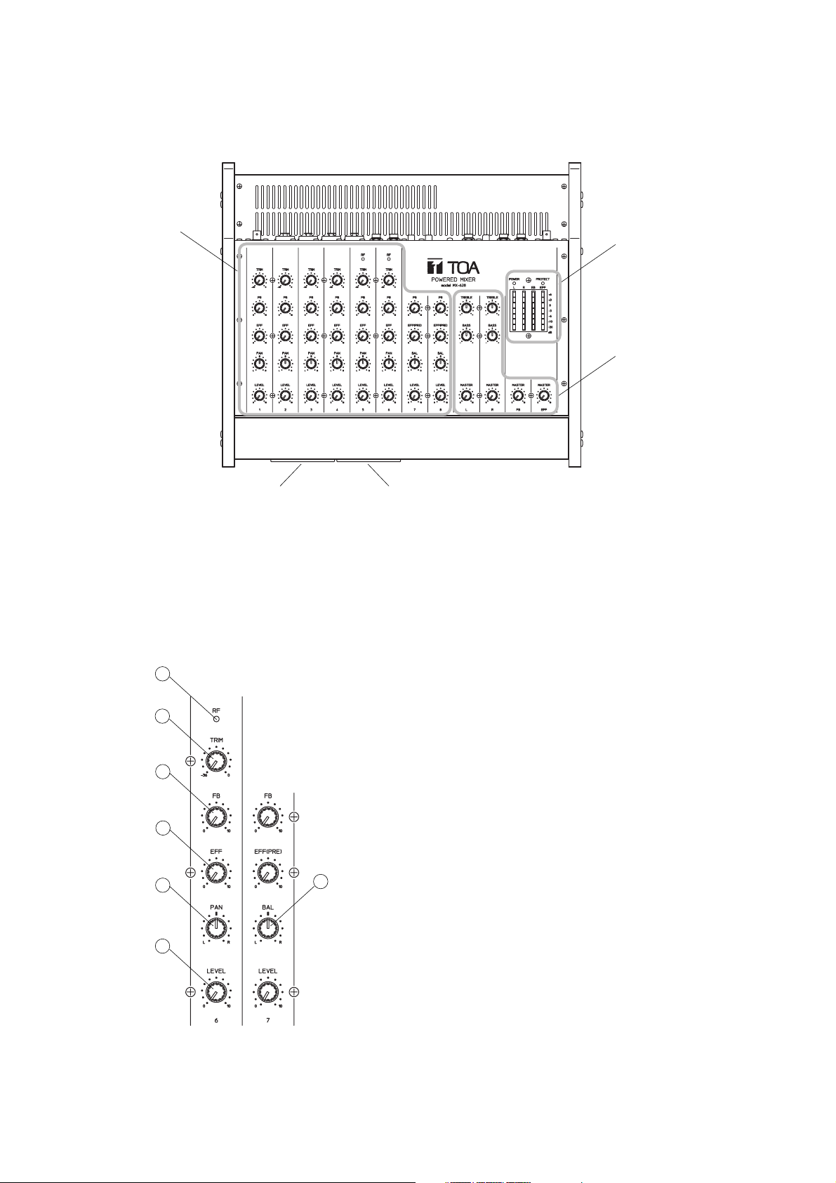
Channel control section
Adjusts a trim, and the output level of panning
potentiometer, sound volume, effector, and foldback
of each channel.
1. Trim Control [TRIM]
Adjusts the amplifier gain depending on the
microphone input level. The gain increases as the
control is rotated clockwise, and decreases as the
control is rotated counterclockwise. The Trim
Control handles the microphone level ranging from
–66 dB to –30 dB. When the microphone input is
distorted, rotate the control counterclockwise till
the distortion is eliminated. The AUX Input is not
equipped with the Trim Control.
2. Foldback Control [FB]
Adjusts the level of a signal to be sent out from
each channel to the Foldback Output.
Note
The foldback output is not influenced by the
Microphone Input and AUX Input Level Control
settings.
3. Effector Output Control [EFF]
Adjusts the level of a signal to be sent out from
each channel to the Effector Output.
Note
The Microphone Effector Output is influenced by
the settings of both the Effector Output Control
and Level Control. It is highly recommended that
the Microphone Effector Output Control be
adjusted after each channel's Level Control has
been set. The AUX Effector Output is not
influenced by the AUX input Level Control setting.
5
4. NOMENCLATURE AND FUNCTIONS
[Operation Panel]
Channel control
section
Master output control
section
Output level indicator
section
Wireless tuner receptacle (Channel 5) Wireless tuner receptacle (Channel 6)
1
2
3
4
5
6
7
Page 6

6
4. Pan-pot [PAN]
Adjusts proportion of a microphone input signal to
be assigned to both the L and R channels. Rotating
the knob clockwise enhances R channel, and
rotating the knob counterclockwise enhances L
channel.
5. Balance Control [BAL]
Adjusts the stereo balance of the AUX input
signal. Rotating the control clockwise enhances R
channel, and rotating the control counterclockwise
enhances L channel.
6. Level Control [LEVEL]
Adjusts each channel's output level.
7. RF Indicator [RF]
This indicator is provided on Microphone Inputs 5
and 6, and lights when the optional wireless tuner
installed in the unit receives a radio signal.
Note
Even if the wired microphone is connected to
Microphone Inputs 5 and 6, the indicator lights
when the wireless tuner receives a radio signal.
However, the signal received by the wireless tuner
is cut off.
Master output control section
8. Equalizer [TREBLE/BASS]
Adjusts high and low frequencies of a speaker
output, recording output and line output signal.
The center knob position provides flat frequency
characteristics. Frequencies are boosted when the
knob is rotated clockwise, and are cut when
rotated counterclockwise.
TREBLE: 10 kHz ±10 dB
BASS: 100 Hz ±10 dB
9. Master Control [MASTER]
Adjusts each output master level.
Note
Recording output is not influenced by the Master
Control setting.
Output level indicator section
10. Power Indicator [POWER]
Remains lit while the power is supplied to the
unit.
11. Protection Indicator [PROTECT]
The speaker output is cut off by means of an
internal relay while this indicator is on.
Note
The Protection Indicator lights for approximately
5 seconds after the power has been switched on
because the speaker output is cut off. However,
this is not a unit failure.
12. Level Meter
Indicates levels of the Speaker Output, Line
Output, Foldback Output and Effector Output.
Note
When the "+6" indicator lights, this indicates the
possibility of output signal distortion. In such
cases, adjust the level with the Master Control
[MASTER] so that the "+6" indicator does not
light.
8
9
10
11
12
Page 7

Input panel section
13.
Microphone Input Terminals 1 – 6 [MIC1 – MIC6]
(XLR-3-31/its equivalent or phone jack)
Input terminals 1 – 6 are connected to the unit's
channels 1 – 6, respectively. These terminals
permit connection of various sound sources
ranging from microphones to line-signal level
equipment depending on the Trim Control
setting, and can be used for both balanced and
unbalanced connections.
Use a phone plug or XLR3-12C connector or its
equivalent when connecting MIC1 – MIC4 inputs,
and a phone plug when connecting MIC5 and
MIC6. As to their pin polarities, refer to the figures
below and on the right.
Wireless microphones can be used on channels
MIC5 and MIC6 by installing an optional wireless
tuner in the unit.
Note
It is impossible to simultaneously use both the
wired and wireless microphones on the same
channel. When the wired microphone is
connected to channel MIC5 or MIC6, the wireless
microphone signal to that channel is cut off.
• Connection plug pin polarity
14. Aux Input Terminals 1 and 2 [AUX1/AUX2]
Connect to the unit's Channels 7 and 8,
respectively. The input is of unbalanced type,
and connects to a pin plug. Terminal 2 can be
converted to Effector Input Terminal by means of
the AUX2/EFF IN Selector Switch.
Note
Channels 7 and 8 are equipped with no trim
control. Therefore, adjust the output level control
of equipment connected to Channels 7 and 8
when a signal is distorted.
7
21222324
131415
16
1819
17
20 20
2526
Input panel sectionOutput panel section
Pin 1: GROUND
Pin 3: COLD
Pin 2: HOT
GROUND HOT
Phone plug (unbalanced type)
GROUND COLD HOT
Phone plug (balanced type)
[Input and Output Panels]
XLR3-12C or its equivalent
Page 8

8
15. AUX2/EFF IN Selector Switch
Sets Channel 8 for AUX2 or Effector Input. Shift
the Switch closer to the AUX2 Terminal to select
AUX2 Input, and to the Effector Terminal to
select Effector Input.
Note
When using an effect sound device, be sure to
shift the AUX2/EFF IN switch to the Effector
Terminal side, and connect the effector's final
output to the Effector Input Terminal. If
connected to the AUX Input Terminal, the
effector will not work properly and in addition, the
unit could oscillate.
16. Effector Input Terminal [EFF IN]
Connects to Channel 8 when the AUX2/EFF IN
Selector Switch is set to the Effector Input
Terminal side. The input is of stereo unbalanced
type, and connects to a balanced phone plug.
Note
Channels 7 and 8 are equipped with no trim
control. Therefore, decrease the output level
control of equipment connected to Channels 7
and 8 to avoid signal distortion.
17. Recording Output Terminal [REC OUT]
Outputs mixed signals of each input individually
for L and R channels. This output is not influenced
by the Master Control setting.
18. Foldback Output Terminal [FB OUT]
Output terminals for foldback signals.
19. Effector Output Terminal [EFF OUT]
Connects to a reverb or other external effectors.
20. Antenna Terminal [ANT A/ANT B]
Connect an optional wireless system antenna to
this terminal when using an optional wireless
tuner.
Output panel section
21. Line Output Terminal [LINE OUT]
Used to expand power amplifiers in such a case
of high-impedance speaker connection for an
example. This output is influenced by the Master
Control setting.
22. Speaker Output Terminal [SPEAKER]
Connects to the speaker. Connect the speaker
so that the total impedance of L and R channels
is 4 – 16 Ω each.
23. Power Switch [POWER]
Switches on or off the unit's power.
24. Grounding Terminal [SIGNAL GND]
This terminal is for signal grounding.
25. Voltage Selector (MX-628 LH only)
Sets the selector to either 115 V or 230 V
depending on your local power source.
26. AC Inlet
Connect the supplied AC power cord to this inlet.
Be sure to set the volume control to the
minimum position before switching on the
unit's power. Failure to do this could impair
your hearing sensation because a big sound
is suddenly output when the power is
switched on.
CAUTION
Phone plug
(For stereo input)
GROUND
HOT (L)
COLD (R)
Page 9

9
5. CONNECTION EXAMPLE
Effector (reverb, etc.)
Recorder (cassette deck, etc.)
Power amplifier
Speaker (for foldback)
Wireless system
antenna
Wireless system
antenna
ININ INOUT
Speaker
Power amplifier
AC mains
Sound source (CD player, etc.)
Dynamic microphone
OUT
Speaker
Speaker (4 – 16 Ω each)
Power amplifier
Line output is influenced
by the Master Control.
IN
Wireless microphone
(Can be used only when a
wireless tuner is installed
in the unit.)
IN
Note
Install the unit in well-ventilated locations. Do not block the unit's ventilation openings nor use the unit in a
box. In addition, keep over 1 m space above the unit.
Page 10

10
6. WIRELESS TUNER INSTALLATION
By installing an optional wireless tuner in the unit, wireless microphones can be used. Prepare the wireless
tuner, antenna, and slotted screwdriver, and follow the procedures below for installation.
Note: Neither the WTU-870 unit nor the WTU-840 unit can be used. If used, the MX-628 may fail.
Antenna terminal Antenna terminal
Cover
Tuner receptacle
1
2
Step 1. Place the unit's Power Switch in the OFF position.
Step 2. Remove the wireless tuner receptacle cover on the
front panel by inserting a slotted screwdriver in the gap
and prying out the cover in the arrow direction as
illustrated.
Step 3. Check to confirm the channel to be used for the
wireless microphone and the tuner's correct orientation,
and then fully insert the tuner. (The illustration assumes
that the tuner is inserted in Channel 5.)
Step 4. Replace the cover by first inserting the arrow
section, and then pushing the arrow section onto
the tuner receptacle.
Step 5. Connect the optional antenna to the unit's antenna
terminal.
2
1
Never insert the slotted screwdriver or metallic
objects in the ventilation slots, as this may
result in fire or electric shock.
WARNING
Page 11

11
7. CONNECTED EQUIPMENT SELECTION
Bear the following points in mind when selecting external equipment to be connected to the unit.
• Note the impedances of the unit and external equipment. It is generally said that by making the output
impedance of signal transmitting equipment equal to the input impedance of signal receiving equipment
(impedance matching) or by making the impedance of the transmitting equipment low and the impedance of
the receiving equipment high, the trouble that could arise when making connections between equipment can
be avoided. The following table shows the recommended impedances of equipment to be connected to the
unit's input and output terminals to provide guidelines on your equipment selection.
• Note the input and output levels of the unit and external equipment. Especially note that the unit cannot
handle an excessive input because the unit's AUX Input and Effector Input (Channels 7 and 8) are not
equipped with a trim control. For external equipment, such as CD players and effectors, select those with an
output level control.
• When the distance between the unit's Microphone Input Terminal (MIC1 – 6) and connected external
equipment exceeds 5 m, select the external equipment with a balanced output terminal whenever possible.
If an unbalanced plug is inserted into the unit's Microphone Input Terminal (MIC1 – 6), the Cold side is
shorted with the ground.
[Each input/output terminal's level and recommended impedance]
Terminal Name
Microphone Input Terminal [MIC1-4]
Trim Control: Minimum (fully counterclockwise)
Maximum (fully clockwise)
Microphone Input Terminal [MIC5 and 6]
Trim Control: Minimum (fully counterclockwise)
Maximum (fully clockwise)
AUX Input Terminal [AUX1 and 2]
Effector Input Terminal [EFF IN]
Recording Output Terminal [REC OUT]
Foldback Output Terminal [FB OUT]
Effector Output Terminal [EFF OUT]
Line Output Terminal [LINE OUT]
Equipped Connector
Equivalent of XLR3-31
Phone jack (balanced type)
Phone jack (balanced type)
Pin jack
Stereo phone jack
Pin jack
Unbalanced phone jack
Unbalanced phone jack
Unbalanced phone jack
Level/Recommended
Impedance
– 30 dB/600 Ω
– 66 dB/600 Ω
– 30 dB/600 Ω
– 66 dB/600 Ω
– 10 dB/10 kΩ
– 10 dB/10 kΩ
– 20 dB/10 kΩ
+4 dB/600 Ω
+4 dB/600 Ω
+4 dB/600 Ω
* 0 dB = 1 V
Page 12

8. PROPER SOUND MIXING
• When connecting the unit to external equipment, check the input and output levels and impedances of both
units carefully before connecting. Note that incorrect connections not only worsen mixing operability, but also
adversely affect the sound quality.
• The unit's microphone input (Channels 1 – 6) is equipped with a trim control which facilitates mixing
operation.
Because the input trim control changes a head amplifier gain by
varying the head amplifier negative feedback amount, the
sufficient dynamic range can be obtained even for a high level
signal by setting the appropriate head amplifier gain. Also, by
decreasing the head amplifier gain, the S/N ratio can be
improved.
For example, suppose that a keyboard with
output level of –20 dB and a –50 dB dynamic
microphone are connected to the unit.
Set the trim controls as shown in the figure on
the right. By adjusting each channel's sound
volume balance with the trim controls, each
channel's level control is set to the same
position, facilitating sound mixing.
Set each channel's level control to graduations
6 – 8 when using, and adjust the whole system
volume with the master control.
12
Head amplifier
Trim control
Input
MIC1 input MIC2 input
Keyboard (–20 dB) Dynamic microphone (–50 dB)
Page 13

13
9. BLOCK/LEVEL DIAGRAM
CH-R
LINE OUT
CH-L
4 Ω
60 W
CH-L
SPEAKER OUT
PA
CH-L MASTER VOL
4 Ω
60 W
CH-R
SPEAKER OUT
PA
CH-R MASTER VOL
LINE OUT
REC OUT
LA
FB OUT
EFF OUT
LA
FOR
POWER AMP
FOR
PREAMP
POWER
SUPPLY
FOR
POWER AMP
FOR
PREAMP
SUPPLY
POWER
SPEAKER
OUT
4 Ω 60 W
FB/EFF/ LINE
REC OUT
FB-VOL
LA
EQUALIZER
MA
PANPOT
TREBLE
BASS
EFF-VOL
CH-VOL
LA
EQUALIZER
MA
FB-VOL
TREBLE
BASS
PANPOT
EFF-VOL
CH-VOL
LED METER
BALANCE
AUX1-VOL
FB MASTER VOL
EFF MASTER VOL
MA
FB-VOL
BA
MA
EFF-VOL
AUX2-VOL BALANCE
AC MAINS
[AS, ER version]
[LH version]
FB-VOL
BA
AC MAINS
EFF-VOL
BA
TRIM
HA
MIC
CH-1 to CH-4
ANT
TRIM
CH-5 to CH-6
TUNER
OPTION
RF DISTRIBUTER
BA
HA
MIC
ANT
BA
CH-7
AUX-1
BA
BA
CH-8
AUX-2
BA
L
EFF
R
0
20
10
+10
-
AUX
TRIM
MINI
+30
+20
IN
MIC
1 to 6
-70-60-50-40-30-
TRIM
MAX
Page 14

14
10. CHARACTERISTIC DIAGRAM
11. DIMENSIONAL DIAGRAM
f=1 kHz
Output Power (W)
Distortion (%)
0.5 1 5 10 50 100
10
-2
10
-1
10
0
5
5
5
Frequency (Hz)
0 dB=1 V
Output Level (dB)
20
0
-
20
10
1
10
2
10
3
10
4
10
5
BASS MAX
BASS MIN
TREBLE MAX
TREBLE MIN
1% distortion
Frequency (Hz)
Output Power (W)
10
1
10
2
10
3
10
4
5
10
20
50
Distortion (power amplifier) Power band width (power amplifier)
Equalizer characteristics
169
150.5
105 36
418
83450
Unit: mm
[Top]
[Side]
Page 15

12. SPECIFICATIONS
* 0 dB = 1.0 V
Note: The design and specifications are subject to change without notice for improvement.
• Accessory
AC power cord ........................................... 1
15
Power Source LH Version: 115 V AC or 230 V AC (selectable), 50/60 Hz
ER AS Version: 230 V AC, 50/60 Hz
Power Consumption 280 W (rated output)
Rated Output 60 W x 2, 4 Ω [0.5% THD (1 kHz)]
Frequency Response 20 Hz – 20 kHz, +1 to –3 dB (AUX input)
Noise
Measured with TRIM & LEVEL controls for MIC1 and MASTER L&R controls set for maximum.
(Speaker Out) Noise level calculated in terms of input: Under –120 dB*
Output noise level: Under –30 dB* (S/N ratio: 54 dB)
Measured with LEVEL control for AUX1 and MASTER L&R controls set for maximum.
Output noise level: Under –66 dB* (S/N ratio: 90 dB)
Maximum Voltage Gain 90 dB (MIC1 – 6 inputs, SPEAKER OUT output)
34 dB (AUX1 – 2 inputs, SPEAKER OUT output)
70 dB (MIC1 – 6 inputs, FB OUT/EFF OUT/ LINE OUT/SPEAKER OUT outputs)
14 dB (AUX1 – 2 inputs, FB OUT/EFF OUT/LINE OUT/SPEAKER OUT outputs)
Equalizer Characteristics
Treble: 10 kHz, ±10 dB
Bass: 100 Hz, ±10 dB
Level Meter 7 points (–20, –10, –6, –3, 0, +3, +6 dB)
Finish Rolled steel plate, gray, paint
Dimensions 450 (w) x 169 (h) x 418 (d) mm
Weight 13 kg
Page 16

 Loading...