

Page 1
Operating Instruction Manual
POWERED MIXER
Model MX-601
Toa Electric Co., Ltd.
KOBE, JAPAN
All manuals and user guides at all-guides.com
all-guides.com
Page 2
General Description
Features
Front Panel [Names of components & their usage]
Rear Panel [Names of Components & their usage]
Connection Examples
Input Connections
How to get a good mix
Block and Level Diagrams
Specifications
Characteristics Diagrams
Appearance
1. XLR Type Audio Connector
The connectors are wired as follows.
The pin 1 is ground (shield,) the pin 2 cold (low, minus), the pin 3 hot (high, plus.)
2. Description of components and functions on the MX-601
Various descriptions are applied, depending on each manufacturer. In our Operating
and Instruction Manual explanation of components and functions is made according to
our usage for them.
2
2
3
4
5
6
7
8
9
10
10
Contents
Precautions
All manuals and user guides at all-guides.com
Page 3
The MX-601 is a compact self-powered mixer with a wide array of sophisticated features —
many of them unavailable on any competitive models. An examination of performance levels
and specifications will reveal the truly professional nature of the MX-601. The rugged construc-
tion and specialized packaging ensure optimum performance and reliability under even the
most demanding "on the road" applications.
The MX-601 features 6 input channels; 1 program, 1 foldback, and 1 effects output. The internal
power amplifier is rated at 120 watts into 8 ohms, 200 watts into 4 ohms, and 300 watts into 2
ohms load.
Each input channel features an electronically balanced XLR connector, and a high impedance
unbalanced 1/4" phone jack. An input trim control is provided to accommodate a wide range of
input source levels. A peak indicator LED detects excessive input signal (either pre or post EQ),
aiding in proper settings of the trim control to avoid input clipping.
Each channel also features 4-band equalization, a "pre" foldback send, a "post" reverb/effects
send, and program level control.
The master control section features a one-octave (10-band) graphic equalizer, high and low
equalizer control of an internal reverberation unit, auxiliary input controls, LED bargraph output
meters, and a full patch bay with our exclusive Bus-Link capability. All master level controls, and
effects return to program and foldback busses are also contained in this section.
1. Six Input channels
2. 300 watts RMS (@ 2 ohms)
3. 10-band graphic equalizer w/bypass switch
4. Auto Comp compression circuitry w/indicator
5. Built-in spring reverberation unit
6. LED bargraph metering
Each Channel
1. Input trim control w/LED peak indicator
2. Pre EQ foldback send
3. 4-band EQ
4. Post effects send
5. Lo-Z balanced XLR input
6. Hi-Z unbalanced 1/4" input
7. Power amp protection circuitry w/indicator
8. Complete patch bay w/buss link
9. AUX and TAPE inputs w/pan and level controls
10. Reverb-effects return to PGM and FB
11. Independent foldback mix
12. Input Channels 5 and 6 have electronically balanced
XLR mic input connector with switchable 40 volts
phantom power
General Description
Features
— 2 —
All manuals and user guides at all-guides.com
Page 4
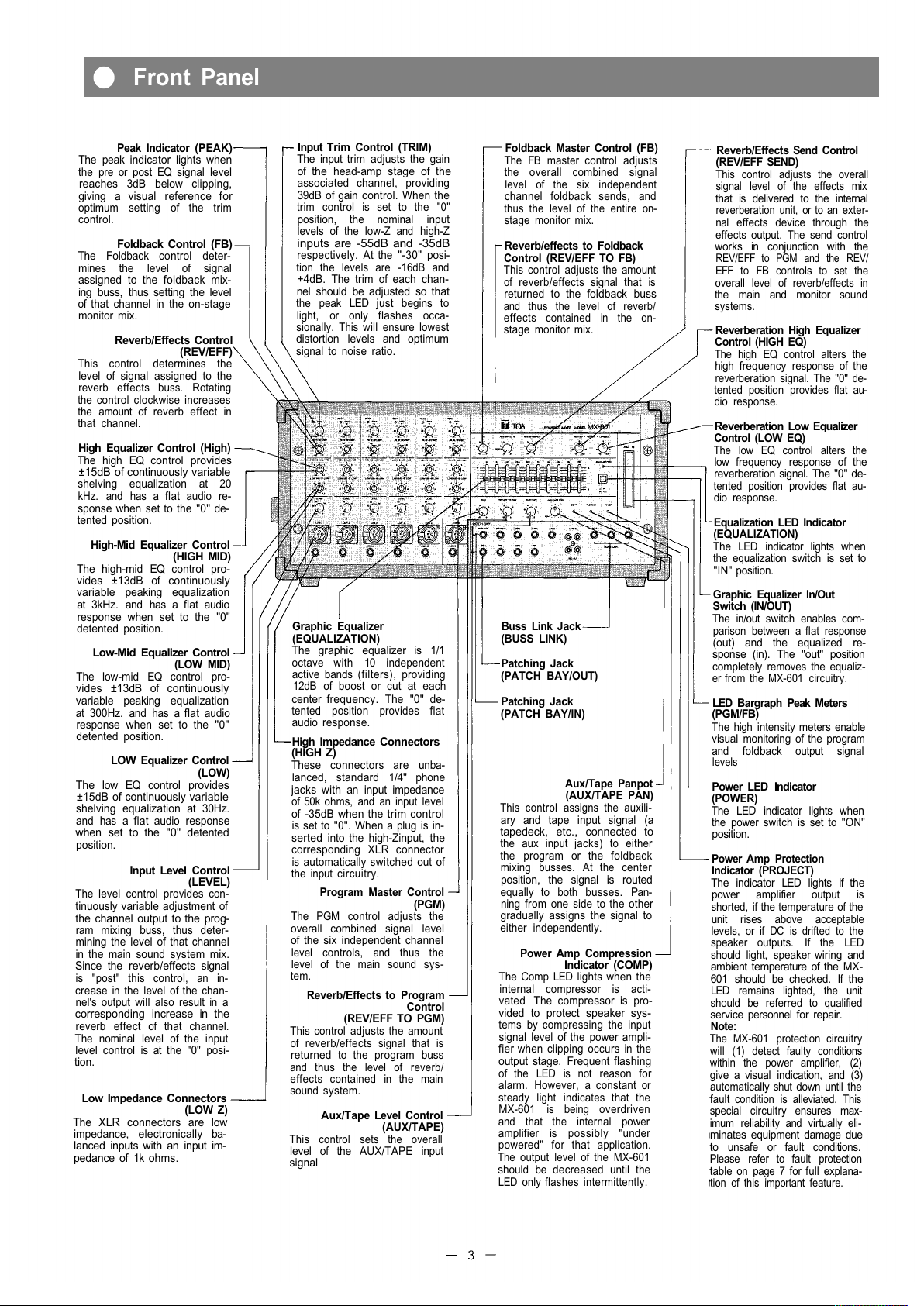
Peak Indicator (PEAK)
The peak indicator lights when
the pre or post EQ signal level
reaches 3dB below clipping,
giving a visual reference for
optimum setting of the trim
control.
Foldback Control (FB)
The Foldback control deter-
mines the level of signal
assigned to the foldback mix-
ing buss, thus setting the level
of that channel in the on-stage
monitor mix.
Reverb/Effects Control
(REV/EFF)
This control determines the
level of signal assigned to the
reverb effects buss. Rotating
the control clockwise increases
the amount of reverb effect in
that channel.
High Equalizer Control (High)
The high EQ control provides
±15dB of continuously variable
shelving equalization at 20
kHz. and has a flat audio re-
sponse when set to the "0" de-
tented position.
High-Mid Equalizer Control
(HIGH MID)
The high-mid EQ control pro-
vides ±13dB of continuously
variable peaking equalization
at 3kHz. and has a flat audio
response when set to the "0"
detented position.
Low-Mid Equalizer Control
(LOW
MID)
The low-mid EQ control pro-
vides ±13dB of continuously
variable peaking equalization
at 300Hz. and has a flat audio
response when set to the "0"
detented position.
LOW Equalizer Control
(LOW)
The low EQ control provides
±15dB of continuously variable
shelving equalization at 30Hz.
and has a flat audio response
when set to the "0" detented
position.
Input Level Control
(LEVEL)
The level control provides con-
tinuously variable adjustment of
the channel output to the prog-
ram mixing buss, thus deter-
mining the level of that channel
in the main sound system mix.
Since the reverb/effects signal
is "post" this control, an in-
crease in the level of the chan-
nel's output will also result in a
corresponding increase in the
reverb effect of that channel.
The nominal level of the input
level control is at the "0" posi-
tion.
Low Impedance Connectors
(LOW
Z)
The XLR connectors are low
impedance, electronically ba-
lanced inputs with an input im-
pedance of 1k ohms.
Input Trim Control (TRIM)
The input trim adjusts the gain
of the head-amp stage of the
associated channel, providing
39dB of gain control. When the
trim control is set to the "0"
position, the nominal input
levels of the low-Z and high-Z
inputs are -55dB and -35dB
respectively. At the "-30" posi-
tion the levels are -16dB and
+4dB. The trim of each chan-
nel should be adjusted so that
the peak LED just begins to
light, or only flashes occa-
sionally. This will ensure lowest
distortion levels and optimum
signal to noise ratio.
Foldback Master Control (FB)
The FB master control adjusts
the overall combined signal
level of the six independent
channel foldback sends, and
thus the level of the entire on-
stage monitor mix.
Reverb/effects to Foldback
Control (REV/EFF TO FB)
This control adjusts the amount
of reverb/effects signal that is
returned to the foldback buss
and thus the level of reverb/
effects contained in the on-
stage monitor mix.
Reverb/Effects Send Control
(REV/EFF SEND)
This control adjusts the overall
signal level of the effects mix
that is delivered to the internal
reverberation unit, or to an exter-
nal effects device through the
effects output. The send control
works in conjunction with the
REV/EFF to PGM and the REV/
EFF to FB controls to set the
overall level of reverb/effects in
the main and monitor sound
systems.
Reverberation High Equalizer
Control (HIGH EQ)
The high EQ control alters the
high frequency response of the
reverberation signal. The "0" de-
tented position provides flat au-
dio response.
Reverberation Low Equalizer
Control (LOW EQ)
The low EQ control alters the
low frequency response of the
reverberation signal. The "0" de-
tented position provides flat au-
dio response.
Equalization LED Indicator
(EQUALIZATION)
The LED indicator lights when
the equalization switch is set to
"IN" position.
Graphic Equalizer In/Out
Switch (IN/OUT)
The in/out switch enables com-
parison between a flat response
(out) and the equalized re-
sponse (in). The "out" position
completely removes the equaliz-
er from the MX-601 circuitry.
LED Bargraph Peak Meters
(PGM/FB)
The high intensity meters enable
visual monitoring of the program
and foldback output signal
levels
Power LED Indicator
(POWER)
The LED indicator lights when
the power switch is set to "ON"
position.
Power Amp Protection
Indicator (PROJECT)
The indicator LED lights if the
power amplifier output is
shorted, if the temperature of the
unit rises above acceptable
levels, or if DC is drifted to the
speaker outputs. If the LED
should light, speaker wiring and
ambient temperature of the MX-
601 should be checked. If the
LED remains lighted, the unit
should be referred to qualified
service personnel for repair.
Note:
The MX-601 protection circuitry
will (1) detect faulty conditions
within the power amplifier, (2)
give a visual indication, and (3)
automatically shut down until the
fault condition is alleviated. This
special circuitry ensures max-
imum reliability and virtually eli-
minates equipment damage due
to unsafe or fault conditions.
Please refer to fault protection
table on page 7 for full explana-
tion of this important feature.
Graphic Equalizer
(EQUALIZATION)
The graphic equalizer is 1/1
octave with 10 independent
active bands (filters), providing
12dB of boost or cut at each
center frequency. The "0" de-
tented position provides flat
audio response.
High Impedance Connectors
(HIGH Z)
These connectors are unba-
lanced, standard 1/4" phone
jacks with an input impedance
of 50k ohms, and an input level
of -35dB when the trim control
is set to "0". When a plug is in-
serted into the high-Zinput, the
corresponding XLR connector
is automatically switched out of
the input circuitry.
Program Master Control
(PGM)
The PGM control adjusts the
overall combined signal level
of the six independent channel
level controls, and thus the
level of the main sound sys-
tem.
Reverb/Effects to Program
Control
(REV/EFF TO PGM)
This control adjusts the amount
of reverb/effects signal that is
returned to the program buss
and thus the level of reverb/
effects contained in the main
sound system.
Aux/Tape Level Control
(AUX/TAPE)
This control sets the overall
level of the AUX/TAPE input
signal
Buss Link Jack
(BUSS LINK)
Patching Jack
(PATCH BAY/OUT)
Patching Jack
(PATCH BAY/IN)
Aux/Tape Panpot
(AUX/TAPE PAN)
This control assigns the auxili-
ary and tape input signal (a
tapedeck, etc., connected to
the aux input jacks) to either
the program or the foldback
mixing busses. At the center
position, the signal is routed
equally to both busses. Pan-
ning from one side to the other
gradually assigns the signal to
either independently.
Power Amp Compression
Indicator (COMP)
The Comp LED lights when the
internal compressor is acti-
vated The compressor is pro-
vided to protect speaker sys-
tems by compressing the input
signal level of the power ampli-
fier when clipping occurs in the
output stage. Frequent flashing
of the LED is not reason for
alarm. However, a constant or
steady light indicates that the
MX-601 is being overdriven
and that the internal power
amplifier is possibly "under
powered" for that application.
The output level of the MX-601
should be decreased until the
LED only flashes intermittently.
Front Panel
All manuals and user guides at all-guides.com
Page 5

Power Amplifier Input Jack
(PWR
AMP)
The PWR Amp input jack
allows the internal power
amplifier to be used with exter-
nal equipment. When a plug is
inserted, the power amp is
automatically disconnected
from the MX-601 mixer section.
The nominal input level is
+4dB with an input impedance
of 10k ohms.
Program Output Jack
(PGM
OUT)
The PGM Out jack is provided
for connection to external
equalizers and/or power amps,
deriving its signal prior to the
internal GEQ and power amp.
Nominal output level is +4dB
with an impedance of 600
ohms.
Effects Output Jack
(EFF
OUT)
The EFF Out jack used in con-
junction with the EFF/RET jack
allows use of an external
effects device in place of the
internal reverberation unit. The
effects out jack should be con-
nected to the input of the ex-
ternal effect unit. Nominal out-
put level is -10dB with an im-
pedance of 600 ohms.
Effects Return
Jack
(EFF/RET)
The EFF/RET jack is provided
to connect an external effe cts
device to the MX-601. When a
plug is inserted the internal re-
verberation unit is automatically
switched out of the MX-601 cir-
cuitry, being replaced by the
external unit. This jack should
be connected to the output of
the external effects unit.
Nominal input level is -20dB
with an impedance of 50k
ohms.
Graphic Equalizer Input Jack
(GEQ)
The CEQ input jack allows the
graphic equalizer to be used
independently of the MX-601
with other external equipment,
or the internal power amplifier
and the graphic equalizer with
external equipment When a
plug is inserted, the main mix
from the program buss is dis-
connected from the graphic
equalizer and the power ampli-
fier. The nominal input level is
+4dB with an input impedance
of 50k ohms.
AUX, AUX2, TAPE Input
(AUX 1, AUX 2, TAPE IN)
-20dB 10k
Program Buss Link Jack
(PGM) (+4dB 22k
)
Fold Back Buss Link (FB)
+4dB 22k
Reverb/Effects Buss Link
Jack
(EFF) +4dB 22k
Buss Link Jacks
The buss link provides direct
access to the PGM, FB, and
effects mixing busses, and is
provided for easy input expan-
sion with additional MX-601 un-
its or other auxiliary equipment.
All jack s have an input level of
+4dB with an impedance of
22k ohms.
Graphic Equalizer Output
Jack
(GEQ
OUT)
This jack allows the MX-601
and the internal graphic
equalizer to be used with an
external power amplifier, or in
conjunction with the GEQ in
jack, to be used independently
of all other MX-601 circuitry.
Nominal output level is +4dB
with an impedance of 600
ohms.
Foldback Output Jack
(FB
OUT)
This jack is for connection to
external power amplifiers and/
or equalizers for the on-stage
monitoring system. Nominal
output level is +4dB with an
impedance of 600 ohms. If the
internal power amp and
equalizer are to be used for
the on-stage monitor system,
the FB output should be con-
nected to the CEQ input jac k.
Recording Output RCA Jack
(REC
OUT)
The Rec Out jack obtains its
signal prior to the program
master output, and is intended
for connection to external re-
cording equipment Nominal
output level is -10dB with an
impedance of 1k ohms.
Power Switch (POWER)
The power switch is a three-
position type with the middle
position being the "off" posi-
tion. The MX-601 should be
operated in the switch position
which produces the lowest
amount of system hum.
Phantom Power Switches
(PHANTOM CH5, CH6)
The Phantom power switch on
both 5 and 6 input channels
permits the user to supply 40V
DC through the input connec-
tors to a condenser mic-
rophone. If phantom power is
not required, the switch must
be in the "off" position.
AC Power Cord
The power cord is the three-wire type with proper grounding
facilities.
Caution - The ground pin should not be removed under any
circumstances. If the MX-601 must be used without proper
grounding facilities, a suitable grounding adapter should be
utilized. Operation of the MX-601 with proper grounding tech-
niques will result in less system noise and greatly reduced
shock hazard.
Speaker Jacks (SPEAKERS)
The speaker outputs are stan-
dard 1/4" phone jacks wired in
parallel. Speaker cables (re-
commend at least #18 gauge
wire) should be connected be-
tween the MX-601 and the
speaker system prior to ap-
plying power to the unit.
Caution - The MX-601 should
never be operated into less
than a 2 ohm speaker load:
— 4 —
Earth Terminal (GND)
AC Fuse
Warning - To avoid possible equipment damage and/or personnel in-
jury, the fuse should always be replaced with same type and rating. Us-
ing improper fuses will also void the warranty The MX-601 should al-
ways be disconnected from AC outlet prior to changing fuses If fuse
repeatedly fails, the unit should be referred to qualified service person-
nel for repair.
Cord Wrap
The cord wrap is provided for
convenient storage of the pow-
er cord when the MX-601 is not
in use
Caution - The power cord
should always be completely
removed from the cord wrap
prior to operation of the unit.
This will insure maximum cool-
ing of the MX-601 For the
same reason, adequate clear-
ance should be maintained be-
tween the rear panel and any
other surface (4-6 inches
should do) The vents on the
bottom and top of the MX-601
are also provided for convec-
tion cooling These vents
should be kept clear and open
Failure to do so may cause
thermal shut-down of the unit.
Front Panel, Patch Bay & Buss Link
Rear Panel
All manuals and user guides at all-guides.com
Page 6

Low Z input should be connected
with low impedance (50 ohm ~ 600 ohm)
microphone
SUB MIXER (MX-601)
Built in Power
Amplifier for
Foldback
From Speaker Jack
on Rear Panel
WIRELESS TUNER
such as WT-740U and
WT-840U
From Speaker Jack
on Rear Panel
KEYBOARD
Line Out
MUSICAL INSTRUMENT
Line Out
CASSETTE TAPE DECK
for recording
MAIN SPEAKER SYSTEM
SPEAKER SYSTEM
for foldback
— 5 —
Connection Examples
All manuals and user guides at all-guides.com
all-guides.com
Page 7

Generally speaking, there are two rules to follow when connecting equipment outputs to the in-
puts of other equipment.
1. Properly match the impedances of the outputs and inputs.
2. Connect low impedance outputs to high impedance inputs.
It goes without saying that not only input and output impedance matching but also level match-
ing should be taken into consideration. Each input channel of the MX-601 is provided with an
input TRIM control, so the usable signal level range is very wide. Input impedances and levels
are shown in the following table.
INPUT SPECIFICATIONS
CONNECTION
INPUT
ACTUAL
LOAD
IMPEDANCE
FOR USE
WITH
NOMINAL
TRIM
POSI-
TION
SENSITIVITY
(PGM OUTPUT
LEVEL +4dB)
MAX BEFORE
CLIP INPUT
LEVEL
CONNECTOR
CH1
CH6
LOW Z
HIGH Z
OPEN
50k
50
to 250
MICRO-
PHONES
50k
OR
LOWER IMP
LINES
0
-30
0
-30
-55dBm (1.38mV)
-16dBm (123mV)
-35dBm (13.8mV)
+4dBm (1.23V)
-34dBm ( 15mV)
+ 1.7dB (0.94V)
-14dBm (150mV)
+20dB (7.75V)
XLR TYPE NC3F
PHONE JACK
AUX
(1~2)
10k.
10k
OR
LOWER IMP,
LINES
-20dBm (77.5mV)
-2dBm (0.61V)
PHONE JACK
EFF/RET
50k
50k
OR
LOWER IMP,
LINES
-20dBm (77.5mV)
-2dBm (0.61V)
PHONE JACK
GEQ
50k
50k
OR
LOWER IMP,
LINES
+4dBm (1.23V)
PHONE JACK
PWR/AMP
10k
10k
LOWER IMP
OR
+4dBm (1.23V)
PHONE JAC K
TAPE
10k
10k
OR
LOWER IMP,
LINES
-20dBm (77.5mV)
-2dBm (0.61V)
PCA PIN JACK
*Sensitivity is the level required to produce a program out level of +4dBm.
All XLR Type connectors are electronic balanced. Phone jack is unbalanced.
If the line going from one piece of equipment to another is long (more than 5m), we recommend
that balanced outputs be connected to balanced inputs.
As is described in the beginning of the Operating Instructions Manual, the connectors of the
MX-601 are wired as follows: Pin 1 is ground (shield). Pin 2 is cold (low, minus). Pin 3 is hot
(high, plus).
Input Connection
s
— 6 —
*0dBm is referenced to 0.775V RMS.
All manuals and user guides at all-guides.com
Page 8

Before connecting other equipment to Powered mixer, check the impedance and level of both.
If the impedances and levels do not match, mixing will be very difficult and the S/N ratio will
also be adversely affected.
Each input channel of the MX-601 is provided with a TRIM control. Thorough understanding of
the function of a TRIM control will make mixing easier.
Trim Control
Input
HEAD AMP
Output
The function of the TRIM control is to control the
negative feedback volume of the head-amp so
that the gain of the head-amp can also be
changed. Because of this, enough dynamic
range, even for high level signals is ensured.
Also, the S/N ratio will be better by decreasing
the gain of the head-amp.
For example, a keyboard, a musical instrument and a dynamic microphone with output levels of
-10dBm, -20dBm and -40dBm respectively are connected to the MX-601.
If the trim control is set as shown in the left fi-
gure, the input level controls can be set to the
same position.
The input level controls are used in general be-
tween -5 and -15.
The peak indicator LED illuminates if the head
amplifier or equalizer is clipping. The gain of the
head-amplifier must be decreased by turning the
trim control counterclockwise.
Key Board in -10dBm level
Musical Instrument in -20dBm level
Dynamic Microphone in -40dBm level
Fault Protection Table
Fault
Excessive current due to
overloads
Short circuits
(less than 0.4-ohm)
Temperature rise of heat
sink
(more than 105°C)
DC drift
Protection
Current limiter activates at
less than 1 ohm.
Current limiter activates,
input signal is lowered,
unit shuts down.
Input signal is lowered
Unit shuts down
Input signal is lowered
Unit shuts down.
Indication
Compressor LED
illuminates
Amp protection LED
illuminates
Amp protection LED
illuminates.
Amp protection
LED illuminates
Action
Remove excessive lords.
Minimum speaker loads 2
ohms
Check speaker lines/
systems for shorts
Check for adequate
ventilation.
Refer to qualified service
personnel.
Restoration
Automatic restoration
after normal loads are
obtained
Turn off power sw itch
Turn on into operational
loads.
Automatic restoration
after temperature lowers
(to 75°C - 95°C)
Automatic restoration
after normal bias is
regained
— 7 —
How to get a good mix
All manuals and user guides at all-guides.com
Page 9

BLOCK DIAGRAMS
LEVEL DIAGRAM
— 8 —
Block and Level Diagrams
All manuals and user guides at all-guides.com
Page 10

MIXER SECTION
Frequency Response
+0, -3dB 30Hz~20kHz (HIGH Zinput TRIM at "-30" position.)
Total Harmonic Distortion
0.05% +4dBm at 1kHz.
Hum and Noise (Open)
Equivalent Input Noise -130dBm (20Hz~20kHz)
Equivalent Input Noise -133dBm (IHF A)
All level Controls Minimum -102dBm (IHF A)
PGM Master at MAX and all
input level controls minimum -93dBm (IHF A)
PGM Master at MAX and one
input level control at MAX -72dBm (IHF A)
Maximum Voltage Gain
INPUT to PGM out 59dB
INPUT to EFF out 45dB
INPUT to FB out 59dB
INPUT to REC out 45dB
INPUT to GEQ out 59dB
AUX to PGM out 24dB
TAPE to PGM out 24dB
EFF/RET to PGM out 24dB
Equalization
32Hz±12dB Peaking 1kHz±12dB Peaking
63Hz±12dB Peaking 2kHz±12dB Peaking
125Hz±12dB Peaking 4kHz±12dB Peaking
250kHz±12dB Peaking 8kHz±12dB Peaking
500Hz±12dB Peaking 16kHz±12dB Peaking
Peak Indicators
Red LED on each input channel LED's turn on at 3dB
below clipping.
INPUT SPECIFICATIONS
OUTPUT SPECIFICATIONS
POWER AMPLIFIER SECTION
Frequency Response
+0, -1dB 5Hz to 40kHz (200W RMS 4
)
Rated Power & Load
300W RMS (2
) 200W RMS (4) 120W
RMS (8
)
Power Output at Clipping
1%
THD, 1kHz
348W RMS (2
) 238W RMS (4
)
140W
RMS (8
)
Total Harmonic Distortion
Less than 0.1% (200mW~200W RMS, 20Hz~20kHz)
Typically below 0.05%
Compresser Dynamic Range
Greater than 26dB
Hum and Noise
At least 110dB S/N ratio, 20Hz~20kHz
At least 113dB S/N ratio IHF-A weighted
Damping Factor
Greater than 200 (1kHz 4
Input Sensitivity
+4dBm (1.23V)
Input Impedance
10k
Output Connector
Phone Jack x 2
Dimensions
588(W)x265(H)x302(D) (23.15x10.43x11.89) inch.
Weight
18.5kg (40.79 Ibs)
*0dBm is referenced to 0.775V RMS.
*Specifications are subject to change without notice.
)
— 9 —
Specification
s
All manuals and user guides at all-guides.com
Page 11

HIGH Z IN. TRIM/MIN. & INPUT EQ
GEQ
POWER AMP POWER BAND WIDTH
POWER AMP TOTAL HARMONIC DISTORTION
POWER AMP COMPRESSOR
REVERBERATION FREQUENCY RESPONSE
— 10 —
sCharacteristic Diagrams
Appearance
All manuals and user guides at all-guides.com
all-guides.com
Page 12

All manuals and user guides at all-guides.com
 Loading...