

Page 1
Thank you for purchasing TOA's Matching Transformer.
Please carefully follow the instructions in this manual to ensure long, trouble-free use of your equipment.
MT-200MATCHING TRANSFORMER
OPERATING INSTRUCTIONS
1. SAFETY PRECAUTIONS
• Before installation or use, be sure to carefully read all the instructions in this section for correct and safe
operation.
• Be sure to follow all the precautionary instructions in this section, which contain important warnings and/or
cautions regarding safety.
• After reading, keep this manual handy for future reference.
When Installing the Unit
• Install the unit only in a location that can
structurally support the weight of the unit and the
mounting bracket. Doing otherwise may result in
the unit falling down and causing personal injury
and/or property damage.
• When installing the unit in the snowy area, take
appropriate measures to prevent snow from lying
on the unit. If the snow lies on the unit, the unit may
fall, causing personal injuries.
• Do not use other methods than specified to mount
the unit. Extreme force is applied to the unit and
the unit could fall off, possibly resulting in personal
injuries.
• Tighten each nut and bolt securely. Ensure that the
mounting bracket has no loose joints after
installation to prevent accidents that could result in
personal injury.
• Do not mount the unit in locations exposed to
constant vibration. The mounting bracket can be
damaged by excessive vibration, potentially causing
the unit to fall, which could result in personal injury.
When Installing the Unit
• Avoid touching the unit's sharp metal edge to
prevent injury.
When the Unit is in Use
• Do not place heavy objects on the unit as this may
cause it to fall or break which may result in
personal injury and/or property damage. In
addition, the object itself may fall off and cause
injury and/or damage.
• Do not stand or sit on, nor hang down from the unit
as this may cause it to fall down or drop, resulting
in personal injury and/or property damage.
• Have the unit checked periodically by the shop
from where it was purchased. Failure to do so may
result in corrosion or damage to the unit or its
mounting bracket that could cause the unit to fall,
possibly causing personal injury.
2. GENERAL DESCRIPTION
The TOA MT-200 is a matching transformer for the HX-5 series and the HX-7 series speaker systems, and
can be used both indoors and outdoors.
WARNING
Indicates a potentially hazardous situation which,
if mishandled, could result in death or serious
personal injury.
CAUTION
Indicates a potentially hazardous situation which,
if mishandled, could result in moderate or minor
personal injury, and/or property damage.
Traceability Information for Europe
Manufacturer:
TOA Corporation
7-2-1, Minatojima-Nakamachi, Chuo-ku, Kobe, Hyogo, Japan
Authorized representative:
TOA Electronics Europe GmbH
Suederstrasse 282, 20537 Hamburg,Germany
Page 2
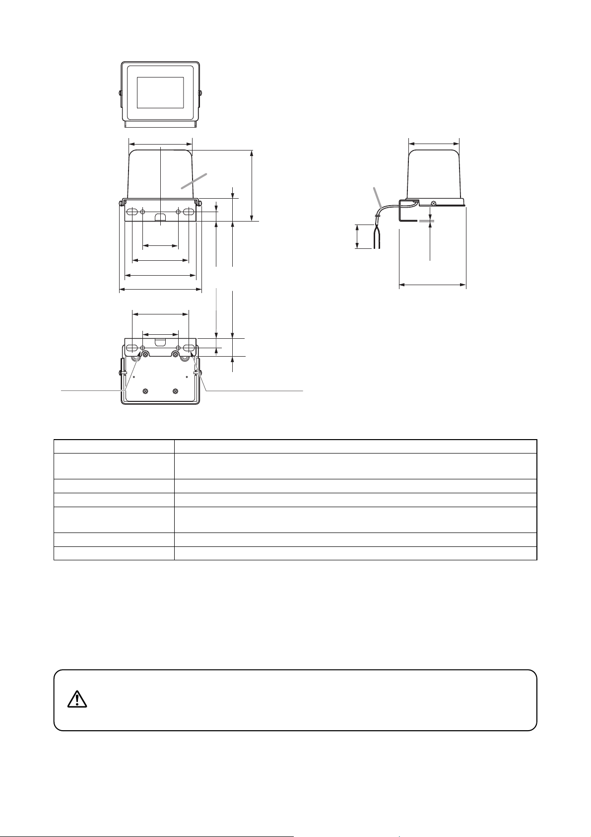
3. DIMENSIONAL DIAGRAM
5. MATCHING TRANSFORMER INSTALLATION
Bolts can be tightened using either a Phillips screwdriver or a wrench, but
be sure to finish the tightening with the wrench to ensure optimum
tightness. Failure to do this could cause the speaker to fall, potentially
resulting in damage and/or personal injury.
WARNING
4. SPECIFICATIONS
* Every speaker module must be aimed horizontally or down to keep the water resistant capability.
Note: The design and specifications are subject to change without notice for improvement.
• Accessories
Hexagon head bolt M8 x 15 (with washers) ......... 2
Rated Input 200 W
Primary Impedance 100 V line: 50 Ω (200 W), 83 Ω (120 W), 167 Ω (60 W)
70 V line: 25 Ω (200 W), 50 Ω (100 W), 83 Ω (60 W), 167 Ω (30 W)
Secondary Impedance 8 Ω
Water Protection IPX4 (the tilt angle must be within 45°)*
Finish Cover: Polypropylene
Mounting bracket: Stainless steel (SUS304)
Dimensions 164 (w) x 141 (h) x 129 (d) mm (6.46" x 5.55" x 5.08")
Weight 2.8 kg (6.17 lb)
5.1. Mounting to the HX-5 Series Speaker System
Note
When the matching transformer is installed on the HX-5 series Speaker System, the optional HY-WM1 series
and HY-CW1 series Speaker Mounting Brackets, and HY-ST1 Speaker Stand Adapter cannot be used.
[Top]
123 (4.84) 99 (3.9)
[Front]
69.9
(2.75)
111 (4.37)
140 (5.51)
164 (6.46)
111 (4.37)
[Bottom]
69.9
(2.75)
Cover
42 (1.65)
35 (1.38)
18.5 (0.73) 18.5 (0.73)
141 (5.55)
[Side]
60 cm (1.97 ft) long
(Primary and secondary)
80
(3.15)
Unit: mm (in)
2 (0.08)
129 (5.08)
4-ø9 (0.35)
4-22 x 12 (0.87 x 0.47)
Page 3

5.1.1. Mounting position
Mount the matching transformer MT-200 in the speaker system's rear mounting plate.
5.1.2. Mounting to the rear mounting plate
Mount the MT-200 in either way (A) or (B) as illustrated below.
Note
When mounting it to the outdoor speaker HX-5B-WP or HX-5W-WP, select either way (A) or (B) to keep the
inclination of the MT-200's top surface within 45° from the vertical axis.
Exceeding this angle range could deteriorate the MT-200's water resistant capability.
Tip
For mounting to the indoor speaker HX-5B or HX-5W,
both ways (A) and (B) are allowed.
5.2. Mounting to the HX-7 Series Speaker System
Note
Prepare an optional HY-MT7 Matching Transformer Adapter when mounting the MT-200 to the HX-7 series
speaker.
For mounting method, refer to the installation manual supplied with the HY-MT7.
[Mounting to horizontally-positioned speakers] [Mounting to vertically-positioned speakers]
Rear mounting plate
HX-5 series
Use the rear mounting plate with its orientation pre-fixed
at the factory.
Remove and attach the rear mounting plate so that its
orientation is as illustrated.
Rear mounting plate
HX-5 series
UP
45°
45°
Matching transformer
MT-200
Hexagon head bolt
M8 x 15 with washer
(accessory)
Rear mounting plate
Top surface
A
B
Page 4

Step 4. Replace the cover and tighten the screws.
Replace the removed cover and securely
tighten the 2 cover fixing screws.
Note
To ensure the splash-proof capability,
press the cover firmly onto the gasket.
Step 3. Connect to the amplifier and the speaker.
Connect the primary cords to the amplifier and the secondary cords to the speaker.
Notes
• Be sure to use a high-impedance amplifier. If the transformer is connected to a low-impedance
amplifier, sufficient sound volume may not be achieved.
• Take care to ensure correct primary and secondary cord connections. Incorrect connections may
cause damage to the amplifier, matching transformer, and speaker system.
6. CONNECTIONS
Step 1. Remove the cover.
Loosen the 2 cover fixing screws to remove the cover, as indicated
by the arrow.
Step 2. Change the primary connection tap.
The tap of the MT-200 is factory-preset to 167 Ω.
Change the setting as required.
To change the tap, reconnect the primary black cord
according to the table below.
Note: Never touch the white cord connected to the COM tap.
Tap
25 Ω 50 Ω 83 Ω 167 Ω
Line
100 V line
–
200 W 120 W 60 W
70 V line 200 W 100 W 60 W 30 W
133-05-00024-00
URL: http://www.toa.jp/
COM
25Ω 50Ω 83Ω167Ω
Cover
Cover fixing screw
Black (+)
White (–)
Primary cord Secondary cord
Black (+)
White (–)
Amplifier
(+)
(–)
Black (+)
White (–)
Cover
HX-5 series
HX-7 series
Speaker terminal
(+)
Speaker terminal
(–)
Cover fixing screw
 Loading...