

Page 1
Features
Security Intercom Systems for critical applications such as corporate, correctional,
educational, government, military, parking structures, police, and others
“Sub-to-Master” and “Master-to-Master” Station Communication
Proven TOA Quality and Reliability
UL-Listed, Manufactured to ISO-9001 Standards
User-Friendly Installation, Setup and Maintenance
Modular Design — Scalable for cost-effective system configurations with easy
system expansion
Station Capacity:
Single Exchange Mainframe:
4 Master stations and 64 Sub-stations
Up to 16 Tie-lined Exchange Mainframes: 64 Master stations and 1,024 Sub-stations
Flexible Programming and Control Software — For setup and maintenance of multiple
exchanges from one PC or remotely via modem
Security System Integration — Communication protocol available for remote control and
monitoring of int ercom system functions from external devices
Comprehensive Call Forwarding Features — Busy,No-Answer, C/O Line and Time-Based
to prevent unanswered calls and allow attendant mobility
Recording Outputs — For individual conversation recording of each master station,
telephone master station and telephone line port with start/stop control activation
Event Logging — All system events are date and time-stamped for PC archiving
Master Station Flexibility — Supports TOA MS-900 or standard Caller-ID analog telephones
Console Master Interface — Allows custom master station fabrication with headset,
microphone, speaker, and key ports
Durable Sub-stations
— Choose from Economy,Indoor,Outdoor, and Panic models,
each with heavy-duty plate, call-switch and optional LED/relay control
Simple “Star Configuration” Wiring — Each station connects to exchange via shielded,
twisted pair (sub) or two twisted pairs (master)
Extended Cable Runs — Master Stations: 7,546 ft. , Sub-stations: 4,265 ft. and Tie-Lined
Exchanges: 4,921 ft.(#20 AWG)
Site Connector Interface — Allows remote exchange connections with fiber optic or
other media converters
Telephone Interface supports two outside C/O telephone lines or trunks
Paging Interface — For external amplifier zone distribution with sixteen control ports
External Source Input — For station and external amplifier zone distribution with
four trigger inputs
Two Year Warranty
The TOA VS-900 SECURITY INTERCOM SYSTEM
provides reliable and intelligible voice communication
for critical security applications, including corporate
security,correctional institutions,educational facilities,
hospital access points, and parking structures. For
over 35 years,TOA has developed a proven track
record of innovative,reliable intercom products,
including the groundbreaking EXES and IC-100 systems.
The TOA VS-900 system is UL and CUL Listed and
manufactured to ISO-9001 standards to ensure
continuous operation for extended periods.
Ideal for applications with multiple “sub”stations
calling in to one or more “master”stations,the VS-900
has a wide range of standard and software programmable features,including comprehensive CallForwarding to allow system operators freedom of
movement and most importantly,to ensure that no
calls go unanswered. The VS-900 integrates easily
with access control and video surveillance equipment via a simple RS-232 communications protocol.
Other features include telephone system integration,
paging and external source distribution, event logging, and recording outputs.
The VS-900 scalable architecture allows the most
cost effective configuration for each application
with easy expansion as the size of the facility grows.
Each exchange mainframe supports up to 4 master
stations and 64 sub-stations. For large systems,
exchanges can be expanded or “tie-lined”to provide
up to 64 master stations and 1,024 sub-stations. The
master stations can be either the TOA MS-900 or standard
off-the-shelf single line telephones with support for
Caller-ID signaling. Sub-stations include Economy,
Indoor,Outdoor, and Panic models,each with heavyduty plate, call switch and optional LED/relay control.
Direct select interface cards provide relays,LED drivers
and switch inputs for custom consoles and annunciator panels.
The VS-900 Security Intercom System is backed with
a two-year warranty.
VS-900
SECURITY
INTERCOM SYSTEMS
VS-900
TOA Electronics, Inc.
Applications
Access Control
Corporate Security
Correctional Institutions
Educational Facilities
Government
Hospital Access Points
Industrial
Military
Parking Garages
Parking Structures
Police
Restricted Door Access
Page 2

P2
F EATURES AND
F UNCTIONS
Scalable Architecture — The expandable, modular design allows you to
specify the most cost-effective station configuration for each installation. A single VS-900MF exchange mainframe supports up to 4 master
stations and 64 sub-stations. You can easily connect up to 16
exchanges for a maximum of 64 master stations and 1024 sub-stations.
Master Station Flexibility — Along with TOA MS-900 Master Stations, the
VS-900 also supports standard analog Caller-ID telephones.*
Direct Select Interface — The Direct Select Interface cards provide external
relays, Call-LED drivers and direct select switch inputs for applications
requiring camera control, access control or custom annunciator panels.
The interface can also be used for custom master stations with headset
interface, microphone input, speaker output and key inputs.
System Integration Solution — VS-900 functions can be both remote con-
trolled and monitored with a serial RS-232 data connection. A simple
communications protocol allows integration with access control and
video surveillance equipment such as camera controllers, PLC’s,and
touch-screens.
Flexible Programming and Control Software — System programming and
maintenance is accomplished with flexible Microsoft Windows®-based
software. Features include system configuration, remote dialing, event
logging and communication monitoring. Systems can be set up at the
office and uploaded to the VS-900 at the job-site. In multi-exchange
systems, you can program and maintain up to sixteen exchanges from
a single connection. Programming and event log data can be easily
saved to disk or printed.
Remote System Management — The software accommodates a dial-up
modem connection for off-site programming and maintenance of up
to 16 exchanges.
Telephone System Integration — With the VS-900CO Telephone Interface
card, you can connect up to two outside telephone lines or trunks to
each exchange allowing the following convenient features.
Call Forwarding — Automatically route station calls to offsite locations.
Outside Line Access — Dialing a pre-assigned access number allows
master stations to access an outside telephone line for outgoing calls.
Direct-In Line/Group Call — Routes incoming telephone calls to individual
or multiple master stations simultaneously.
Direct-In Dial — Incoming telephone line callers can dial specific master
or sub-stations directly.
Master Station Features — The TOA MS-900 Master Station includes a 12-
digit alphanumeric LCD,clock,8 programmable auto-dial keys and the following convenient functions.
Alphanumeric Station Numbering — For easily recognizable dialing and
display,station numbering is fully programmable for both 2 to 6 digit
and 8 alphanumeric characters.
Call-In Display Priority — Sub-stations can be assigned either
Emergency or Normal display priority in the master station queue
during multiple station call-in.
Call Queuing — Up to 64 incoming calls can be queued in order of
pre-assigned priority and answered in any order. Once an existing call
is terminated, the next call moves to the top of the queue.
Selective Response — The master station operator can scroll through a
list of multiple incoming calls and select a specific station call to answer.
Redial — The master station operator can redial the last dialed key
sequence with a single key operation.
Call Hold — The master station operator can place an answered call on hold.
Call Transfer — The master station operator can place an answered call
on hold, dial a third party and then either transfer the original calling
party or return to the original conversation.
Auto-Dial — Each master station operator can assign frequently dialed
station numbers or dialing sequences to eight programmable keys to
allow convenient one-touch operation.
Multiple Communication Modes — Depending on the type of station in
use, users have the choice of Handset, Hands-free and Press-to-talk
(Simplex) Communication.
Call Forwarding — Incoming calls to a master station can be forwarded
internally, manually or automatically, to another master station or
group of master stations or externally, to an outside telephone number
or PBX extension.
Manual Forwarding — Each master station can manually dial a key
sequence to route future sub-station calls to a new destination.
Remote Forwarding (Call Capture) — Sub-station calls to a master station
can be forwarded to a new destination from a remote master station
location.
Time-Based Forwarding (Automatic) — Sub-station calls to a master
station can be automatically forwarded at a pre-programmed time to a
new destination and then automatically reset to normal operation.
Ideal for shift changes or off-hours security.
No Answer Forwarding — Sub-station calls to a master station can be
automatically forwarded to other master stations, outside telephone or
PBX extension after a specific number of unanswered rings.
Busy Forwarding — Sub-station calls to a master station can be automatically forwarded to a master station or outside telephone if the
called master station is busy.
Off-Site Forwarding / Outside Line Call Forwarding — Station calls can
also be routed via Call Forwarding to a preprogrammed outside
telephone number.
Master Station Group Call — Routes incoming sub-station calls to
multiple master stations simultaneously.
Conference / Emergency Conference — Any master station can initiate a
conference with up to two other master stations. A pre-assigned four
station emergency conference can also be initiated with a single key sequence.
Audio Monitoring — Real-time audio monitoring of pre-programmed
sub-station groups with automatic scrolling and stop/forward/back
control.
Event Logging — System events are stored with station numbers, date
and time stamp for PC archiving.
Voice Recording — All master station,telephone master stations and
telephone line ports have individual recording outputs for recording
conversation audio. Each has an associated control port for start/stop
control of an external recording device for the beginning and end of
the conversation.
Paging — Master stations and telephone master stations can initiate
paging to up to 19 sub-station zones, All-Zones and Emergency
All-Stations/Zones. A separate Paging Output is also available for connection to an external paging amplifier along with 16 programmable
control outputs for external relay activation.
Automatic Time-out — A preprogrammed time limit allows automatic ter-
mination of Incoming Station Calls, Conversations and Paging.
External Source Input — Line input for connecting an external music
source or tone generator. Four programmable trigger inputs distribute
the external source to pre-programmed zones.
*See VS-900 Operating Instructions for details on Telephone Master Station features.
Page 3
MS-900 MASTER S
TATION
P3
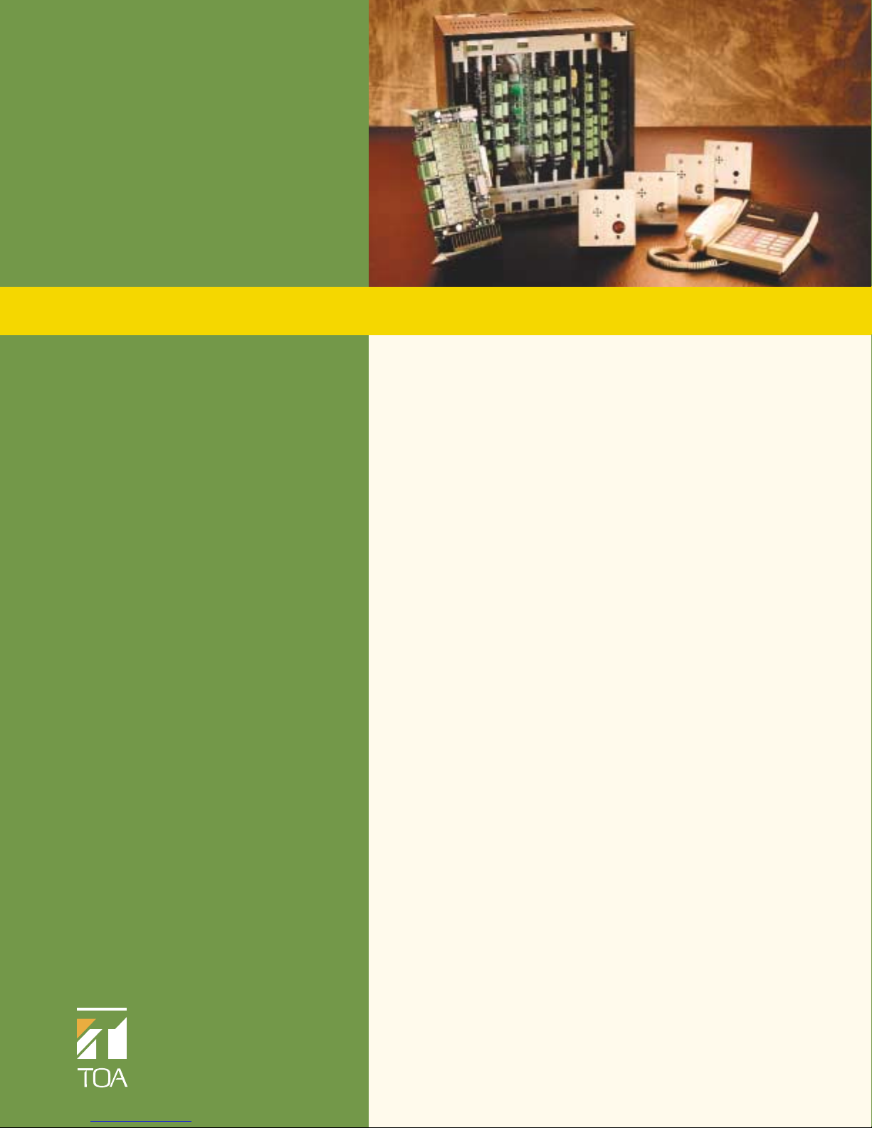
MS-900
Master Station
Connects to VS-900MS card using
two-twisted pair wiring
Handset and hands-free speaker/
microphone
Alpha-numeric, 12 character display
Digital clock display
In-use indicator
Eight programmable auto-dial keys
Press-to-talk, redial and transfer keys
Station number directory
Adjustable speaker volume and
microphone sensitivity
Speaker High/Low volume selector
switch
Standard RJ-11 telephone jack
External speaker terminals for high
ambient noise areas
Wall-mount bracket included
Power Source 24 VDC (supplied from the VS-900MS)
Communication Modes Duplex, half-duplex and PTT
Frequency Response 300 – 3,400 Hz
(Speech)
Handset Microphone/ Dynamic type, 150 ohms
Speaker
Handsfree Microphone Electret condenser microphone
Station Speaker Dynamic type, 8 ohms,2.24” (57 mm),0.6 W
Key Pad Membrane switches
Display 12 digit LCD
Auto-Dialing 8 keys (programmable)
Station Speaker Volume 2-step selection slide switch
Control
Handset Speaker Volume Volume,0 to +12 dB
Control
Installation Method Desk/Wall-mount
Wiring Two twisted pair cables
Connectors Modular jack (RJ-11 type)
External speaker output:screw terminal (8 ohms,0.6 W)
Operating Temperature 32
º
- 104º F (0º- 40ºC)
Finish ABS resin, pale white
Dimensions (W x H x D) 8.50" x 2.93" x 8.39"
(216 mm x 74.5 mm x 213 mm)
Weight 2.07 lbs.(940 g)
Maximum Service Distance* 24 AWG 2,953 ft./0.56 mile (0.9 km)
22 AWG 4,921 ft./0.93 mile (1.5 km)
20 AWG 7,546 ft./1.43 mile (2.3 km)
*Distance may be limited by job site conditions.
REGISTER
HANDSET
SP. VOL.
ON
OFF
MIN.
MAX.
Rear View
216
ABC
DEF
21
3
GHI
JKL
MNO
4
5
6
PRS
TUV
WXY
7
8
9
OPER
#
*
0
PTT
C
UNIT:mm
Do not connect this jack
to telephone line.
LINE
74.5
69.5
2
1
3
5
7
REDIAL XFER
208
4
6
8
213
Top View Side View
83.5
21
60
125
80.5
94
Wall mounting bracket
Page 4
P4
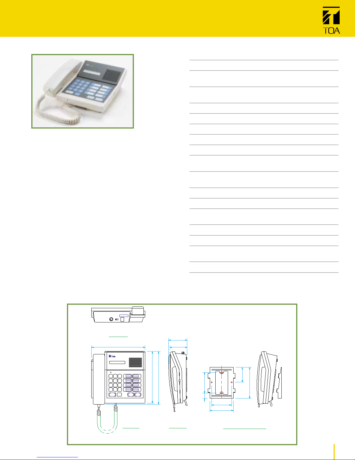
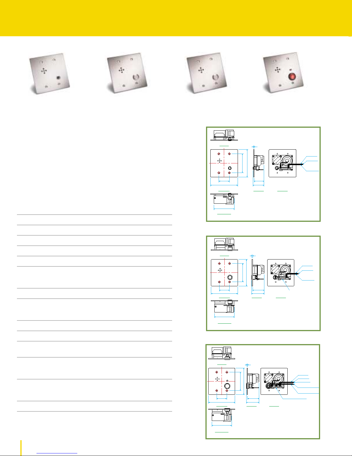
VS-900 SUB
- STATIONS
RS-150
RS-160/RS-170
RS-180
Heavy-duty brushed stainless steel faceplate,#11 GA (RS-150:#14 GA)
Vandal-resistant call button (except RS-150)
Weather-resistant models (RS-170 and RS-180)
Connects to VS-900RS card using shielded,twisted pair wiring*
Mounts in two-gang deep electrical box with adapter ring
(supplied by others)
RS-180
Red vandal-resistant call button
Red Call Assurance LED for ADA-compliance
Control output – open collector-type for external relay control
Labeling area for ADA-compliant message
RS-150
Economy Indoor Sub-station
RS-160
Indoor Vandal Sub-station
RS-170
Outdoor Vandal Sub-station
RS-180
Outdoor Panic Sub-station
Input Power 1 W
Impedance 625 ohms (1 W @ 25 V line)
Output SPL (1 W/1 m) 82 dB SPL
Frequency Response 300 to 4k Hz
Internal Speaker 1.57” (4 cm) Mylar cone
Sensitivity as Microphone -40 dB (0 dB = 1 V/Pa)
Faceplate Brushed stainless steel
RS-150: #14 gauge (2 mm)
RS-160/170/180: #11 gauge (3 mm)
Weather-Resistant Coating Synthetic rubber sealant (RS-170/180)
Call Button RS-150:Resin, black
(Momentary-action) RS-160/170: Stainless steel,silver
RS-180: Aluminum,red
Call LED (RS-180) Red LED
Control Output (RS-180) Open-collector type, 30 mA,24 VDC
Ambient Temperature RS-150:
+14º– +
122ºF (-10º– +50ºC)
RS-160/170/180:+14º– +131ºF (-10º– +55ºC)
Dimensions Faceplate:4.72” x 4.72”(120 mm x 120 mm)
Maximum depth: 2.1”(52.5 mm)
Mounting hole spacing: 1.81”x 3.28” (46 mm x 83.5 mm)
Weight RS-150: 0.90 lbs (410 g)
RS-160/170: 1.19 lbs (540 g)
RS-180: 1.26 lbs (570 g)
Accessories Nickel-plated steel,slotted, oval head screw No.6 - 32 (4 pcs.)
Maximum Service Distance** 24 AWG 1,640 ft./0.31 miles (0.5 km)
22 AWG 2,625 ft./0.5 miles (0.8 km)
20 AWG 4,265 ft./0.81 miles (1.3 km)
*Note: Fiber optic interfaces available from others.
**Distance may be limited by job site conditions.
Top View
46
120
Front View
90
Bottom View
UNIT:mm
Top View
46
120
Front View
2
120
83.5
43.5
48.5
Side View Rear View
3
120
83.5
52.5
57.5
Rear ViewSide View
Black (C)
Brown (B)
Orange (A)
Black (C)
Brown (B)
Orange (A)
Weather-resistant coating (RS-170)
90
Bottom View
UNIT:mm
Top View
46
120
Front View
90
Bottom View
UNIT:mm
3
Black (C)
Brown (B)
120
83.5
52.5
58.5
Rear ViewSide View
Orange (A)
White
(Open collector: Hot)
Blue
(Open collector: COM)
Weather-resistant coating
Page 5

VS-900 EXCHANGE
M AINFRAME
P5
Mainframe for system cards
Supports up to 4 master stations and 64 sub-stations
Requires one PU-200 Power Supply for 32 sub-stations
and 2 PU-200 for 33-64 sub-stations
24 VDC input for backup power supply
ON/OFF Switch
LED’s for Status Indication
Microsoft Windows®-based PC required for system
programming
All programming stored in non-volatile EEPROM
2 RS-232 ports (programming / logging)
Rack-mount brackets included (10 RU)
Optional wall-mount bracket, model YC-303
VS-900MF
Exchange Mainframe
Power Source 20 VAC,24 VDC
Current Consumption 7 A
Speech Path Configuration Time sharing digital switch
Internal Sound Source 12 types
Serial Ports Complies with the RS-232C Standard,D-sub connector
(9-pin, female),2 ports
Installation Method Rack-mount or wall-mountable with YC-303
Other Real time clock for time control
Unit presence/non-presence detection
System programming
Power switch
Connectors Bus connector: DIN connector (64-pin,female) x 9
(2) PU-200 connection terminal: 4-pin x 2
24 VDC input terminal:4-pin (with grounding terminal)
Operating Temperature 32
º
- 104ºF (0º- 40ºC)
Finish Pre-coated steel plate, black,30% gloss
Dimensions (W x H x D) 16.54” x 17.47”x 11.35” (420 x 443.7 x 288.3 mm)
Weight 28 lbs.(12.7 kg)
Accessories (included) Rack-mount bracket (2) and screws (8)
Mounting screw (M4 x 10) (6)
Cable clip (20)
4-pin removable terminal block (3)
Lithium battery (CR2032)
Floppy disk (Microsoft Windows®-based software) (2)
Operating/Installation/Software manuals (1 set)
Slot Card Type
1 VS-900MS Master Station Line Card (2 ports)
or
VS-900AL Telephone Master Station Line Card (2 ports)
2 VS-900MS Master Station Line Card (2 ports)
or
VS-900AL Telephone Master Station Line Card (2 ports)
3 VS-900RS Sub-station Line Card (16 ports)
4 VS-900RS Sub-station Line Card (16 ports)
5 VS-900RS Sub-station Line Card (16 ports)*
6 VS-900RS Sub-station Line Card (16 ports)*
7 VS-900CO C/O Telephone Line Card (2 ports)
8 VS-900AF Audio Function Card (paging/input/conference)
9 VS-900TI Tie-Line Interface Card (multi-exchange)
*Add second PU-200 Power Supply for 3 or more VS-900RS.
UNIT:mm
Top View
420
466.6
483.6
Front View
Front view without front panel
POWER
101.6101.637.8 164.9
443.7
MAIN FRAME VS-900MF
288.3
Side View
Page 6

YC-303
PN-100B
PU-200
P6
VS-900 EXCHANGE
M AINFRAME
PU-200
Power Supply for VS-900MF
Connects to the VS-900MF and provides two 20 VAC outputs
One PU-200 supports 1 or 2 VS-900RS, two PU-200
support 3 or 4 VS-900RS
Wall-mount brackets included
Optional rack-mount panel, model PN-100B
Power Requirements 110/120 VAC, 50/60 Hz
Output Voltage 20 VAC x 2
Output Current 2.5 A x 2
Finish Color steel plate,ivory
Dimensions (W x H x D) 6.30” x 2.68”x 7.01” (160 x 68 x 178 mm)
Weight 6.17 lbs.(2.8 kg)
Accessories (included) Round head wood screw (3.5 x 25) (4)
Fuse (125 V,4 A) (2)
Fuse (250 V,2 A) (1)
Wall-mount brackets (2)
PN-100B
Rack-Mount Panel for (2) PU-200 (4 RU)
YC-303
Wall-Mount Bracket for VS-900MF
Finish Steel, black,electrode position paint
Dimensions (W x H x D) 15.41” x 17.32”x 2.28” (391.4 x 440 x 58 mm)
Weight 4.63 lbs.(2.1 kg)
Accessories (included) Wood screw (5.1 x 38) (4)
Tapping screw (4 x 12) (4)
160
140
120
18
Mounting Hole (1/1)
UNIT:mm
4-7φ10.5
Side View
165
145
WARNING
TO REDUCE THE RISK OF FIRE AND ELECTRIC SHOCK, DO NOT
INTERCONNECT OUTPUT TERMINATIONS.
AVERTISSEMENT
NE PAS INTERCONNECTER LES BORNES DE SORTIE.
CAUTION
TO REDUCE THE RISK OF ELECTRIC SHOCK, DO NOT REMOVE COVER.
NO USER SERVICEABLE PARTS INSIDE. REFER SERVICING TO QUALIFIED SERVICE PERSONNEL.
ATTENTION
REDUIRE LES RISQUES DE SECOUSSE ELECTRIQUE, NE PAS
ENLEVER LE COUVERCLE. CAR AUCUNNE PIECES INTERIEURES NE SONT UTILISABLE POUR LES
UTIRISATEURS. DEMANDEZ A VOTRE PERSONNEL QUALIFIE.
WARNING
TO REDUCE THE RISK OF FIRE OR ELECTRIC SHOCK, DO NOT EXPOSE
THIS APPLIANCE TO RAIN OR MOISTURE.
INTENDED FOR INSTALLATION IN A PROTECTED ENVIRONMENT.
Top View
VOLTAGE SELECTOR
POWER TRANSFORMER
Top View
model PU-200
TOA Corporation
MADE IN JAPAN
20V AC 2.5A 20V AC 2.5A
OUTPUT
Front View
120V AC110V AC
LISTED
CLASS 2
POWER SUPPLY
R
9T11
Class 2
110/120VAC
50/60Hz
140W
φ10
4
115
178
R
65
68
10
177
UNIT:mm
466
483
Front View
290
338
391.4
Front View Side View
Mainframe
VS-900MF
36.2 7866 78 78
Bottom View
UNIT:mm
Side View
37.7 101.6
99200
440
58
Page 7

VS-900 LINE
C ARDS
P7
VS-900MS
Master Station Line Card
Two MS-900 Master Station ports
Two Recording Line outputs
Two Recording Control outputs (open collector)
Removable terminal blocks
VS-900RS
Sub-station Line Card
Sixteen RS Sub-station ports
Two talk paths/speech links (one
speech, one speech/paging)
Paging input and output for external
paging amplifier connection
Removable terminal blocks
VS-900AL
Telephone Master Station Line Card
Two standard analog telephone ports*
Caller-ID Signalling
Two Recording Line outputs
Two Recording Control outputs (open collector)
Removable terminal blocks
Number of Lines 2 lines
Conversation Recording Audio signal: 0 dBV, unbalanced
Output Control signal: Open collector output,24 VDC max.
Control current:20 mA
Connectors Mainframe: DIN connector (64-pin, male)
Line output: 4-pin x 2
Recording audio/control output:4-pin x 2
VS-900MS
VS-900AL
Number of Lines 2 lines
Conversation Recording Audio signal: 0 dBV, unbalanced
Output Control signal: Open collector output,24 VDC max.
Control current:20 mA
Selectable Signal Type DTMF
Monitoring Function Line loop detection function
Applicable Terminal Telephone sets to comply with FCC Part 68
Control Function Call signal transmission,audible signal transmission,
caller identification signal transmission (Caller ID Function)
Connectors Mainframe: DIN connector (64-pin, male)
Line output: 2-pin x 2
Recording audio/control output:4-pin x 2
Maximum Service Distance Loop resistance less than 500 ohms (including
telephone)
VS-900RS
Number of Lines 16 Sub-station lines
Number of Links 2 links (1 Speech, 1 Speech/Paging)
Paging Output Unbalanced,-20 dBV, 2k Ω
Paging Input Balanced,25 V line amplifier,16 W min.
Conversation Method Half-duplex conversation by voice-operated switch
or simplex conversation by PTT switch
Power Output 1 W @ 25 V line per speech link
Other Call button detection function and speech link
control function
Connectors Mainframe: DIN connector (64-pin, male)
Sub-station:Two-core shielded cable (3-pin) x 16
* Telephone equipment supplied by others
Page 8

P 8
VS-900 INTERFACE
C ARDS
VS-900CO
C/O Telephone Interface Card
Two Outside Telephone (C/O) Line ports
Two Recording Line outputs
Two Recording Control outputs (open collector)
Removable terminal blocks
VS-900AF
Audio Function Card
Paging Line output
Sixteen Paging Control outputs (open collector)
External Source Line input
Four External Source Trigger inputs for zone
distribution
Link for Conference and Emergency Conference
features
Removable terminal blocks
VS-900CO
Number of Lines 2 lines
Conversation Recording Audio signal: 0 dBV, unbalanced
Output Control signal: Open collector output,24 VDC max.
Control current:20 mA
Selectable Signal Type DTMF
Signal Format Loop start and Ground start compatible
Main Functions DTMF dial signal transmission function,
DTMF signal detection function
Call signal (receiving) detection
Connectors Mainframe: DIN connector (64-pin, male)
C/O line: 4-pin x 2
Recording audio/control output:4-pin x 2
VS-900AF
Paging Output Audio output: 1 output, 0 dBV, unbalanced, 1k Ω
Control output:Open collector output, 24 VDC max.
Control current:20 mA
External Source Audio input: 1 input,0 dBV, unbalanced,22k Ω
Distribution Control input: 4 inputs, no-voltage make contact
Open voltage:24 VDC,short circuit current:20 mA
Conference Link 1 link (up to 4-party conference)
Connectors Mainframe: DIN connector (64-pin, male)
External interface side:Voice output 2-pin
Control output 2-pin x 16
Voice input 2-pin
Control input 2-pin x 4
Page 9

P 9
VS-900 MULTI-EXCHANGE S YSTEMS
VS-900TI
Tie-Line Interface Card
Required in each VS-900MF exchange
in a multi-exchange tie-lined system
(16 maximum)
Multi-drop (bussed) configuration
simplifies wiring
Up to four Voice Links (4x Send/4x
Receive), two twisted pair wiring each*
One Data Link, RS-485, shielded twisted
pair wiring
Removable terminal blocks
Number of Audio Links 4 links
Connection Format Multi-drop (bussed)
Transmitting System Data: RS-485
Voice:Base band
Input/Output Level Voice: 0 dBu,balanced
Data:In compliance with RS-485 Standard
Other Exchange number setting function
Connectors Mainframe: DIN connector (64-pin, male)
Tie-line interface side: 4-pin x 4 (Voice line)
4-pin x 1 (Data line)
Maximum Bus Length 24 AWG 1,969 ft./0.37 mile (0.6 km)
(All Exchanges)* 22 AWG 3,281 ft./0.62 mile (1 km)
20 AWG 4,921 ft./0.93 mile (1.5 km)
*Distance may be limited by job site conditions. To connect exchanges using fiber optic hardware, use
the VS-900SC Site Connector, page 10. Fiber optic interfaces available from others.
Tie-Line Up to Sixteen VS-900MF Exchange Mainframes
Exchange #1
POWER
Exchange #2
POWER
Exchange #16
POWER
MAIN FRAME VS-900MF
Maximum Bus Length (#20 AWG): 0.93 miles (1.5 km)
MAIN FRAME VS-900MF
Four Voice Links (two twisted pair wiring each)
RS-485 Data Link (shielded, twisted pair wiring)
MAIN FRAME VS-900MF
Page 10

P 10
VS-900 SITE
C ONNECTOR I NTERFACE
VS-900SC
Site Connector Tie-Line Interface
Allows you to connect exchanges using standard
audio fiber interfaces or other media converters
(supplied by others)
Combines up to four voice links from two exchanges
Two exchange systems requiring fiber or other media
connection do not require the VS-900SC
Requires external power supply, model PU-200
To determine the number of VS-900SC, subtract “two”
from the total number of VS-900MF Exchange Mainframes. For example, a system with ten VS-900MF will
require eight VS-900SC.
System Example
Site #1
Building A
VS-900MF
w/ VS-900TI
RS-485 Data Link
(shielded, twisted pair wiring)
Site #2
Building B
Four Voice Links
(two twisted pair wiring each)
POWER
MAIN FRAME VS-900MF
POWER
VS-900SC
Fiber I/F
Fiber Optic Link
Fiber I/F
Fiber I/F
Site #3
Building C
POWER
Fiber Optic Link
VS-900SC
Fiber I/F
MAIN FRAME VS-900MF
VS-900MF
w/ VS-900TI
Building D
POWER
MAIN FRAME VS-900MF
VS-900MF
w/ VS-900TI
MAIN FRAME VS-900MF
VS-900MF
w/ VS-900TI
Notes:
1. All VS-900TI must be converted to fixed-direction voice links.
2. Fiber Interfaces supplied by others.
Page 11

VS-900 DIRECT
S ELECT I NTERFACE
P11
VS-900DI
Direct Select/Master Station Interface Card
Supports up to (32) VS-910DI Direct
Select I/O cards
Connects between MS-900 Master Station
and VS-900MS port
Use standalone without MS-900 to
provide interface for custom master
stations.
Headset port
Microphone input
Speaker output (1 W, 8 Ohms)
Key Input terminals (XFER, PTT, C)
In-use Indication output
Requires 24 VDC (1 A) power supply,
model XPS-24VS
Mountable in user-supplied console
or enclosure
VS-910DI
Direct Select I/O Card
Connects to VS-900DI (32 max.)
32 Programmable Relay outputs
(24 VDC, 1 A)
32 Programmable Call-LED drivers
(Open collector type)
32 Programmable Direct Select
Switch inputs
Relays Programmable to
Activate at Call In or Call Answer
Requires 24 VDC (1 A) power supply,
model XPS-24VS
Mountable in user-supplied console
or enclosure
Power Source 24 VDC ±10%/1 A
Maximum Number of 4 per exchange,64 per system (16 tie-lined exchanges)
Connectable VS-900DI Cards
Function Key Input One each of [C], [PTT], [Xfer],and [Test] keys, dry contact, 5 VDC/0.5 mA
Contact resistance:<50 ohms, 8-pole screwless terminal
Communication Line 1 line for VS-900 exchange (VS-900MS card) and 1 line for MS-900
master station,One 6-position/4-contact modular jack for each line
In-Use Indication Output Open collector output,24 VDC/approx. 100 mA,2 pole screwless terminal
Electret Microphone Input Microphone sensitivity: -75 to -65 dBV, 5 VDC phantom power supply,
2-pole screwless terminal
Speaker Output Speaker impedance: 8 ohms, power output: 1 W maximum, 2-pole
screwless terminal
Headset Connection Microphone sensitivity: -75 to -65 dBV, speaker impedance: 200 to
400 ohms,detection jack contact input [Det.]: 5 VDC/10 mA, contact
resistance:<10 ohms,8-pole screwless terminal
PC Interface RS-232C D-sub connector (9 poles,female type)
Maximum Service Distance* 24 AWG 2,953 ft./0.56 mile (0.9km)
(including MS-900) 22 AWG 4,921 ft./0.93 mile (1.5 km)
20 AWG 7,546 ft./1.43 mile (2.3 km)
*Distance may be limited by job site conditions.
Power Source 24 VDC ±10%/1 A
VS-910DI Ports 32 relay outputs (call- or response-activated relay output),24 VDC/1 A,
50-pole “CHAMP” IDC (Amphenol) connector*
32 open collector outputs (for LED indication of incoming and outgoing
calls) 24 VDC/approx.100 mA, 50-pole “CHAMP” IDC (Amphenol) connector*
32 switch inputs (for calling and response switch operation),dry contact,
5 VDC/0.5 mA,contact resistance: <50 ohms,50-pole “CHAMP”IDC
(Amphenol) connector*
Maximum Number of 32
VS-910DIs per VS-900DI
Maximum Number of Ports 1,024 relay outputs (call- or response-activated relay output)
per Full VS-910DI-Mounted
System 1,024 open collector outputs (for LED indication of incoming and
outgoing calls)
1,024 switch inputs (for calling and response switch operation)
* Mating connectors supplied by others.
VS-900DI
VS-910DI
Page 12

Master Sub-stations
2
VS-900MF PU-200 VS-900MS/AL VS-900RS VS-900CO
3
VS-900AF
3
VS-900TI
Stations
1
464122 4110
8 128 2 4 4 8 2 2 2
12 192 3 6 6 12 3 3 3
16 256 4 8 8 16 4 4 4
20 320 5 10 10 20 5 5 5
24 384 6 12 12 24 6 6 6
28 448 7 14 14 28 7 7 7
32 512 8 16 16 32 8 8 8
36 576 9 18 18 36 9 9 9
40 640 10 20 20 40 10 10 10
44 704 11 22 22 44 11 11 11
48 768 12 24 24 48 12 12 12
52 832 13 26 26 52 13 13 13
56 896 14 28 28 56 14 14 14
60 960 15 30 30 60 15 15 15
64 1024 16 32 32 64 16 16 16
P12
TOA Electronics, Inc.
601 Gateway Boulevard
Suite 300
South San Francisco, CA 94080
Tel: 800-733-7088
Fax: 800-733-9766
www.toaelectronics.com
© 2003 TOA Electronics,Inc.
VS-900 SYSTEM
C ONFIGURATION
1
TOA MS-900 Master Station or analog (DTMF) telephone (supplied by others)
2
RS-150, RS-160,RS-170,RS-180
3
Optional, see page 8 for details
Literature Order #:L-VS-900
Specifications subject to change without notice.
Windows® is a registered trademark of Microsoft Corporation.
Visit www.toaelectronics.com to download:
Installation and Operating Manuals
Estimate Worksheet
Architects and Engineering Specifications
Control Software
CAD Files
Application Notes
 Loading...