

Page 1
1
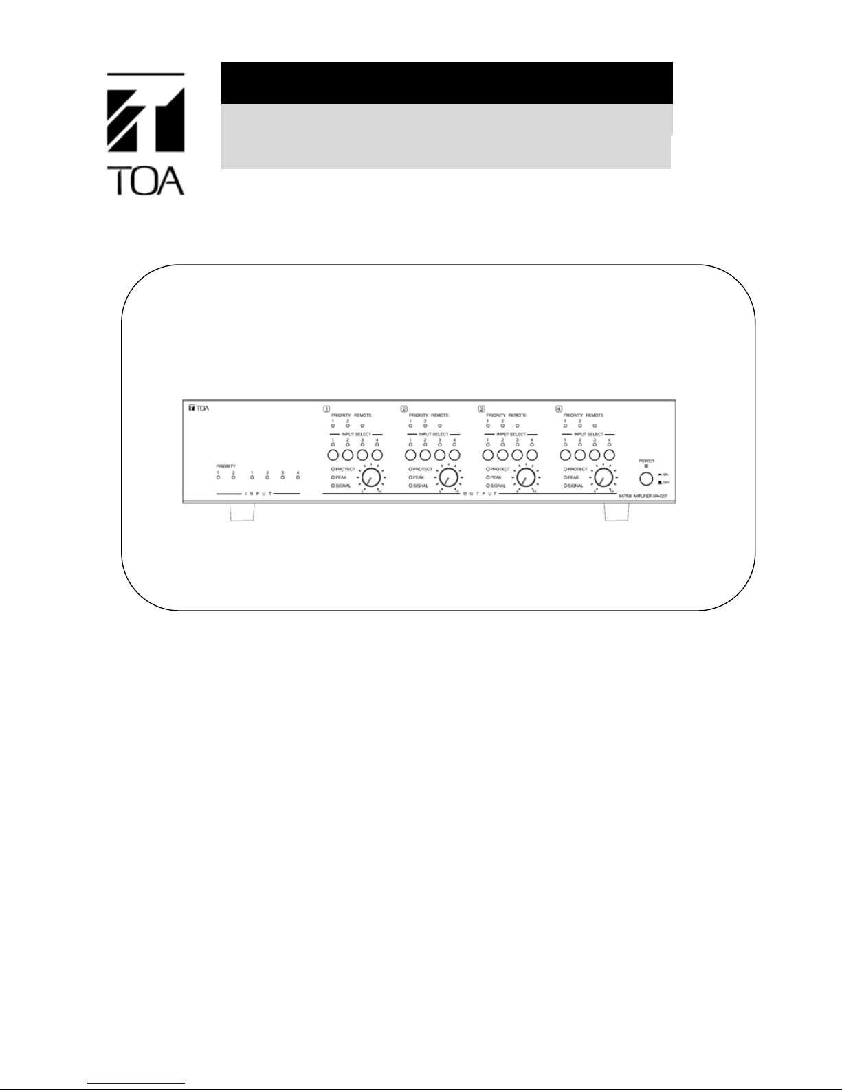
SERVICE MANUAL
MATRIX AMPLIFIER
MATRIX PRE-AMPLIFIER
MA-725F
MM-700F
Page 2

2
TABLE OF CONTENTS
NOTE ON REPAIR WORK SAFETY ......................................................................................................................... 3
About lead-free solders ............................................................................................................................................. 4
GENERAL DESCRIPTION ........................................................................................................................................ 4
SPECIFICATIONS ..................................................................................................................................................... 5
NOMENCLATURE AND FUNCTIONS ...................................................................................................................... 7
BLOCK DIAGRAM ................................................................................................................................................... 12
WIRING DIAGRAMS ............................................................................................................................................... 13
TROUBLESHOOTING ............................................................................................................................................ 15
MOUNTING DIAGRAMS ......................................................................................................................................... 17
EXPLODED VIEWS AND PARTS LISTS ................................................................................................................ 23
Rework SOP ............................................................................................................................................................ 27
Page 3

3
WARNING
NOTE ON REPAIR WORK SAFETY
Follow the instructions below, both to prevent accidents when making repairs and to ensure post-repair product
safety.
Do not apply voltages other than those specifi ed for the equipment or its components.
Applying voltages other than the rated voltage could cause electrical breakdown or over-current, possibly resulting
in electric shock or fire.
Use specified parts and components.
Be sure to use only specified parts when replacing parts indicated by the mark in the circuit diagram or parts list.
Because such parts have been designed for safety in terms of their incombustibility and dielectric strength, using
parts other than those specified could result in a fi re.
After replacing parts, be sure to return the new parts and any other affected parts to their
previous configuration.
After using insulators like tubing and tape, reinstalling floating parts on the printed circuit board, or replacing parts
mounted behind the circuit board, be sure to restore all parts and pieces to their original mounting positions. In many
cases, such parts have been installed in such a way as to prevent excessive heat build-up, and failing to restore
them to such positioning may create a fi re hazard.
Check that all screws, parts, and wiring removed or changed during servicing have been restored to their original
states. Also, confirm that no damage has occurred around the serviced area.
Restore changed wiring to its original state.
Internal wiring has been laid out to prevent wires from passing too close to parts that generate a lot of heat or that
carry high voltages. Therefore, if wiring has been re-routed, clamped, or otherwise altered during servicing, be sure
to restore the wiring to its original state once servicing is completed. Leaving internal wiring too close to such hot or
high-voltage parts could result in noise, electric shock, or fi re.
Do not modify the design of circuit boards or other electronic elements.
Modifying circuit boards could cause electric shock or result in a fi re hazard due to excessive heat buildup.
User modification automatically exempts the manufacturer from all personal and property liability caused by such
modification, and the user who carried out such modification shall be solely responsible for such accidents.
Conduct safety inspections following the completion of service.
1. Check that all screws, parts, and wiring removed or changed during servicing have been restored to their original
states. Also, confirm that no damage has occurred around the serviced area.
2. If parts from the power supply's primary side have been replaced, make sure that at least 3 millimeters of space
has been left between the terminals or soldered portions of the primary side's live charging section and peripheral
metal parts.
3. After servicing the power supply section, perform the following insulation safety check.
(1) Remove the power plug from an AC wall outlet.
(2) Disconnect all connections to the antenna and external equipment, then turn on the power switch.
(3) Using a 500-volt megohmmeter, check that the insulation resistance value between each of the power plug's
terminals and external exposed metal sections (video input/output terminals, audio input/output terminals, etc.) is
10 MΩ or more.
(4) If the insulation resistance value is less than 10 MΩ, check again to see if the replaced parts have been
mounted correctly and also if contacts or soldering have been established correctly.
Hazardous voltages are present inside the equipment. When replacing the pc board assemblies
or parts, be sure to disconnect the power cord to avoid electric shock that could result from
accidental contact with these parts.
When measuring the test point voltages, be sure to wear protective gloves.
Page 4

4
About lead-free solders
Since lead can become an environmental contaminant, this unit has been manufactured using solders that contain
no lead in the printed circuit board.
[While conventional solders are alloys of tin and lead, lead-free solder is comprised of an alternative alloy that
contains no lead.]
NOTES
• Circuit boards using lead-free solder bear a lead-free solder designation. To maintain the integrity of this
designation, be sure to use lead-free solder when repairing such lead-free solder circuit boards.
Boards not marked with the lead-free solder designation may legally be serviced using conventional solders.
• Because the melting point of lead-free solder (approximately 220°C) is 30°C-40°C higher than that of conventional
(tin-lead alloy) solder, it takes little longer to melt. It is recommended that a soldering iron with controllable
temperature be used and set to 20°C higher than would normally be used with conventional solder.
Identifying printed circuit boards that use free-lead solder
Printed circuit boards that use lead-free solder have the following designation printed or stamped on either side of
the board.
Pb PbF
GENERAL DESCRIPTION
TOA's MA-725F matrix amplifier and MM-700F is all-in-one solution for multi-channel or multi-zone
applications combined 6x4 audio matrix, DSP and 4ch Class-D amplifier (*) into one chassis. It is equipped
with 4 independent line inputs, 2 MIC/LINE priority inputs. Each output has independent DSP preset
adjustment also comes with input source matrix selection. It features a high power handling (250Wx4 @
70V/100V) (*) and various inputs capabilities. Its wide range of applications include general or emergency
announcement and background music playing at restaurants, pubs, retail stores, schools, offices and etc.
(*) MA-725F only
Page 5
5
SPECIFICATIONS
■SPECIFICATION
(* 0dB = 1V)
Model Number MA-725F
Power Source 100 - 240V AC, 50/60Hz
Power Consumption
1350 W (rated output), 200 W (based on cULus standards), 42.5 W (idle),
22 W or less (Stand-by)
Frequency Response 20Hz - 20 kHz (-3dB / +1dB, LPF OFF)
Total Harmonic
Distortion
1% or less, at 1kHz, rated output
Certification cULus 60065, EN60065, EN55032, EN55020, FCC part15 class A
Input PRIORITY 1, 2:
Mic -60dB* / Line -10dB* selectable, 2.2kΩ, electrically balanced,
removable terminal block
LINE IN 1,2,3,4: -10dB*, 10kΩ, unbalanced, 2 RCA jacks (Stereo summing)
Output
SPEAKER
1,2,3,4:
70V (20Ω), 100V (40Ω), removable terminal block
LINE OUT
1,2,3,4:
0dB*, 600Ω, unbalanced, RCA jack
MOH: 0dB*, 600Ω, transformer balanced, removable terminal block
DSP Preset 16 presets in 4 banks at each output channel, selectable
S/N Ratio Mic: 60 dB* or more, Line: 75dB* or more (A-weighted)
Muting Manual mute / Automatic mute
Mute Hold Time 50ms - 10 seconds, adjustable
Priority Level PRIORITY 1 > PRIORITY 2 > LINE 1,2,3,4
Control POWER: ON/OFF switch, Power remote terminal
PRIORITY 1,2:
MIC/LINE selector switch, Gain control, Assign switch, Auto mute
switch, Mute sense control,
Manual mute terminal, Mute hold time control, Priority mix switch
LINE IN 1,2,3,4: Gain control, Assign restriction switch
OUTPUT 1,2,3,4:
LINE IN 1-4 selector switch, Output gain control, 70V/100V
selector switch, HPF switch,
DSP bank selector switch, DSP preset selector switch
REMOTE 1,2,3,4: Remote control connector (RJ-45), Remote link switch
Indicator POWER: 1 Power LED
PRIORITY 1,2: 1 Signal LED
LINE IN 1,2,3,4: 1 Signal LED
OUTPUT 1,2,3,4:
2 Activated PRIORITY LED, 1 Connected REMOTE LED, 4
Selected LINE LED
1 Signal LED, 1 Peak LED, 1 Protect LED
Operating Temperature
0⁰C to 40⁰C (32⁰F to 104⁰F)
Operating Humidity 35% to 80%RH (no condensation)
Finish Panel: Aluminum, hair line, black
Case: Steel plate, black, paint
Dimension 420(W) X 103.4(H) X 350(D) mm (16.54" X 4.07" X 13.78")
Weight 7.6kg (16.7 lbs.)
Accessories
Power cord (2m, 5.65ft.)···1, Removable terminal plug (5 pins···2, 3pins···1, 2
pins···4),
Rack mounting bracket···2, Bracket mounting screw···4, User's manual···1
Option Remote controller: WP-700
Page 6
6
■SPECIFICATION
(* 0dB = 1V)
Model Number MM-700F
Power Source 100 - 240V AC, 50/60Hz
Power Consumption 9W or less
Frequency Response 20Hz - 20 kHz (-3dB / +1dB)
Total Harmonic Distortion 1% or less, at 1kHz, rated output
Certification cULus 60065, EN60065, EN55032, EN55020, FCC part15 class A
Input PRIORITY 1, 2:
Mic -60dB* / Line -10dB* selectable, 2.2kΩ, electrically balanced,
removable terminal block
LINE IN 1,2,3,4: -10dB*, 10kΩ, unbalanced, 2 RCA jacks (Stereo summing)
Output
LINE OUT
1,2,3,4:
0dB*, 600Ω, unbalanced, removable terminal block
MOH: 0dB*, 600Ω, transformer balanced, removable terminal block
DSP Preset 16 presets in 4 banks at each output channel, selectable
S/N Ratio Mic: 60 dB* or more, Line: 75dB* or more (A-weighted)
Muting Manual mute / Automatic mute
Mute Hold Time 50ms to 10 seconds, adjustable
Priority Level PRIORITY 1 > PRIORITY 2 > LINE 1,2,3,4
Control POWER: ON/OFF switch, Power remote terminal
PRIORITY 1,2:
MIC/LINE selector switch, Gain control, Assign switch, Auto mute
switch, Mute sense control,
Manual mute terminal, Mute hold time control, Priority mix switch
LINE IN 1,2,3,4: Gain control, Assign restriction switch
OUTPUT 1,2,3,4: LINE IN 1-4 selector switch, Output gain control,
DSP bank selector switch, DSP preset selector switch
REMOTE 1,2,3,4: Remote control connector (RJ-45), Remote link switch
Indicator POWER: 1 Power LED
PRIORITY 1,2: 1 Signal LED
LINE IN 1,2,3,4: 1 Signal LED
OUTPUT 1,2,3,4:
2 Activated PRIORITY LED, 1 Connected REMOTE LED, 4
Selected LINE LED
1 Signal LED, 1 Peak LED
Operating Temperature
0⁰C to 40⁰C (32⁰F to 104⁰F)
Operating Humidity 35% to 80%RH (no condensation)
Finish Panel: Aluminum, hair line, black
Case: Steel plate, black, paint
Dimension 420(W) X 103.4(H) X 350(D) mm (16.54" X 4.07" X 13.78")
Weight 5.7kg (12.3lbs)
Accessories
Power cord (2m, 5.65ft.)···1, Removable terminal plug (5 pins···2, 3pins···1, 2
pins···4),
Rack mounting bracket···2, Bracket mounting screw···4, User's manual···1
Option Remote controller: WP-700
Note: The design and specifications are subject to change without notice for improvement.
Page 7
7
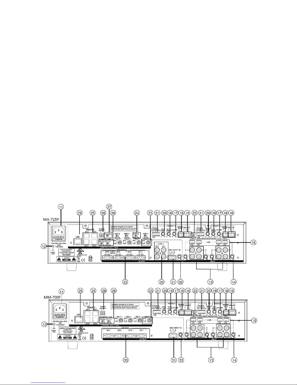
NOMENCLATURE AND FUNCTIONS
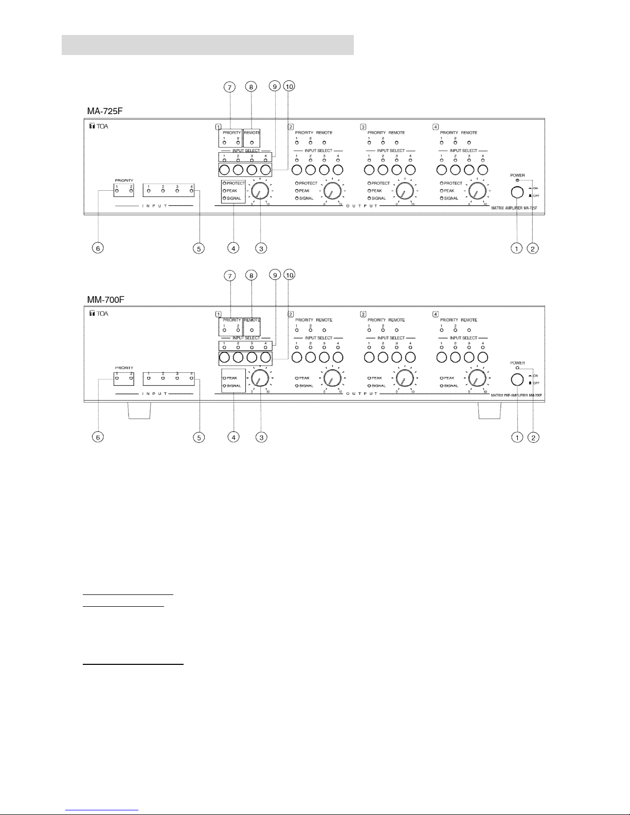
[Front]
1 POWER SIWITCH [ON /OFF]
Press this switch to turn on the amplifier, press the switch again to turn off the amplifier.
2. POWER INDICATOR [POWER] (Blue)
During the power on process the indicator flashes, after amplifier is ready, the indicator lights.
3. CH1 OUTPUT LEVEL CONTROL
Adjust CH1 output level
Note: The functionality of CH2, CH3, CH4 is the same as CH1.
4. CH1 SIGNAL, PEAK, PROTECT INDICATOR (Green, Red, Red)
SIGNAL Indicator (*): When output level exceeds -36 dBV, the SIGNAL indicator lights.
PEAK Indicator (*): Lights red when an output signal clips (distortion occurs).
Note: When the Peak indicator lights, turn the output level control (3) counterclockwise until its light extinguishes or
decrease the input signal level of the connected external device. Operating the unit while the Peak indicator
remains lights may cause the protection circuitry to be activated.
PROTECT Indicator (*): Lights or blinks when the protection circuitry is activated. When the power is switched on,
this indicator lights for about 2 seconds and then extinguishes.
Note: The functionality of CH2, CH3, CH4 is the same as CH1.
5. LINE 1, LINE 2, LINE 3, LINE 4 INPUT SIGNAL INDICATOR (Green)
When LINE 1, LINE 2, LINE 3, LINE 4 input signal is exceed -47dBV, the indicator lights.
6. PRIORITY INPUT SIGNAL INDICATOR [PRIORITY 1, PRIORITY 2] (Green, Green)
Page 8
8
PRIORITY INPUT SIGNAL1 Indicator: When the priority input 1 signal (14) exceed -36dBV (line)/-86dBV
(mic) the indicator lights.
PRIORITY INPUT SIGNAL2 Indicator: When the priority input 2 signal (14) exceed -36dBV (line)/-86dBV
(mic), the indicator lights.
7. CH1 PRIORITY INDICATOR [PRIORITY1, PRIORITY2] (Green, Green)
PRIORITY 1 Indicator:When PRIORITY 1 is activated and assigned to CH1 output, the indicator lights.
PRIORITY 2 Indicator:When PRIORITY 2 is activated and assigned to CH1 output, the indicator rights.
Note: 1. When PRIORITY MIX 1+2 switch is turned on and activated, these two indicator light at the same time.
2. The functionality of CH2, CH3, CH4 is the same as CH1.
8. CH1 PRIORITY INDICATOR [REMOTE] (Yellow)
When remote control panel WP-700 is connected to CH1 of REMOTE TERMINALS, the indicator lights.
At this time, both output level and input source selection could be changed by connected WP-700.
Note: 1. When WP-700 is connected, CH1 OUTPUT LEVEL CONTROL (3) and CH1 INPUT SELECT
SWITCH (10) on the front panel are defeated and controlled by WP-700.
2. When WP-700 is disconnected, the output level goes back to the setting of CH1 OUTPUT LEVEL
CONTROL( 3)
3. The functionality of CH2, CH3, CH4 is the same as CH1.
9. CH1 INPUT SELECT INDICATOR [1, 2, 3, 4] (Green)
The led will light with respect to the input select by the INPUT SELECT SWITCH (10) other channel which is
not selected will turn off.
Note: The functionality of CH2, CH3, CH4 is the same as CH1.
10. CH1 INPUT SELECT SWITCH 1 - 4
Select from LINE 1-4 inputs as the input source for amplifier CH1 output. Select again on the previous
selected input turns off the selection of input source.
Note: The functionality of CH2, CH3, CH4 is the same as CH1.
(*) MA-725F only
[Rear]
Page 9

9
11. AC inlet
Connect the supplied power cord to this inlet. The socket-outlet should be installed near the equipment and
the plug (disconnected device) shall be easily accessible.
12. Functional ground terminal [SIGNAL GND]
Hum noise may be generated when external equipment is connected to the unit. Connecting this terminal to
the functional ground terminal of the external equipment may reduce the hum noise.
13. LINE 1, LINE 2, LINE 3, LINE 4 INPUT TERMINAL
10 kΩ,–10 dB*,unbalanced RCA Jack (Upper and lower of RCA input signal is mixed)
Connect music source equipment: e.g: CD players.
14. LINE 1, LINE 2, LINE 3, LINE 4 INPUT LEVEL CONTROL
Adjust the input level (sensitivity) of LINE 1, LINE 2, LINE 3, LINE 4.
15. ASSIGNMENT RESTRICTION DIP SWITCHES (LINE 1, LINE 2, LINE 3, LINE 4)
Assign restriction LINE 1, LINE 2, LINE 3, LINE 4 to CH1, CH2, CH3, CH4 outputs.
LINE 1 ASSIGNMENT RESTRICTIONS:
Switch No.
ON OFF
1 LINE 1 can’t be assigned to CH1 LINE 1 can be assigned to CH1
2 LINE 1 can’t be assigned to CH2 LINE 1 can be assigned to CH2
3 LINE 1 can’t be assigned to CH3 LINE 1 can be assigned to CH3
4 LINE 1 can’t be assigned to CH4 LINE 1 can be assigned to CH4
Note: 1) The functionality for LINE 2, LINE 3, LINE4 is the same as LINE 1.
2) When the assignment restriction is set, both INPUT SELECT SWITCH (10) or connected WP-700,
are not allowed to select the restricted channel.
16. MIC/LINE input terminal (PRIORITY 1, PRIORITY 2)
MIC: 2.2Kohm, –60 dB*/ LINE: 2.2Kohm, –10 dB*, electronically-balanced inputs of 3-pin removable terminal
block type.
Connect microphone or line level music source equipment. MIC/LINE gain could be from the PRIORITY
FUNCTIONAL DIP SWITCH (21) #6.
17. MIC/LINE input level control (PRIORITY 1, PRIORITY 2)
Adjust the input level (sensitivity) of the MIC/LINE
18. Manual mute terminal
Open voltage: DC 3.3V, Short current: <5mA
1) When (+), (-) shorted: The selected LINE 1, LINE 2, LINE3, LINE4 input signal to CH1, CH2, CH3, CH4
output will be muted, and switch to the page channel (1st ~4th switch of (21)) that have been assigned by
PRIORITY 1, PRIORITY 2 inputs.
2) When (+), (-) opened:CH 1, CH 2, CH 3, CH 4 output will gradually recovered from the previous assigned
LINE 1, LINE 2, LINE3, LINE4 signal. The recovery time is controlled by the HOLD TIME control (20).
19. MUTE SENSE control (PRIORITY 1, PRIORITY 2)
Adjust the threshold (sensitivity) of the mute function of the PRIORITY 1, PRIORITY 2 inputs. In other words,
if PRIORITY 1, PRIORITY 2 input signal exceed the threshold that set by MUTE SENSE, it will mute the
LINE 1, LINE 2, LINE 3, LINE 4 signal to CH1, CH2, CH3, CH4 outputs. Rotate clockwise will raise the
sensitivity, counter-clockwise will lower the sensitivity.
20. HOLD TIME control (PRIORITY 1, PRIORITY 2)
Adjust the recovery time of the LINE 1, LINE 2, LINE 3, LINE 4 to CH1, CH2, CH3, CH4 outputs. Rotate
clockwise will increase the recovery time (maximum 10sec), counter-clockwise will decrease the recovery
time (minimum 50ms)
Page 10
10
21. PRIORITY FUNCTIONAL DIP SWITCH (PRIORITY 1, PRIORITY 2)
Control the functionality of the PRIORITY 1 and PRIORITY 2
Switch No.
ON OFF
1 PRIORITY 1/2 can be switched to CH1 output PRIORITY 1/2 cannot be switched to CH1 output
2 PRIORITY 1/2 can be switched to CH2 output PRIORITY 1/2 cannot be switched to CH2 output
3 PRIORITY 1/2 can be switched to CH3 output PRIORITY 1/2 cannot be switched to CH3 output
4 PRIORITY 1/2 can be switched to CH4 output PRIORITY 1/2 cannot be switched to CH4 output
5 The mute function is controlled by the PRIORITY
1/2 input signal or manual mute (18)
The mute function is only controlled by the
manual mute (18)
6 PRIORITY 1/2 input gain switch to MIC level PRIORITY 1/2 input gain switch to LINE level
22. PRIORITY MIX1+2 switch
Control the input mode of the PRIORITY 1/2
ON OFF
PRIORITY 1 and PRIORITY 2 will be mixed and output
to CH1, CH2, CH3, CH4 when mute activated. The
PRIORITY FUNCTIONAL DIP SWITCH (21), MUTE
SENSE control (19), HOLD TIME control (20) will be
followed by PRIORITY 1’s setting
The PRIORITY 1 has the higher priority level than
PRIORITY 2. When There is mute function activated.
Unit will output PRIORITY 1’s input first.
23. EQ BANKS and PRESETS SELECTION
The 2-bit DIP switch select the bank of respect to the 16 EQ presets. Total 4 banks.
The 4-bit rotary switch selects 16 EQ presets from each banks.
Note: The functionality of CH2, CH3, CH4 is the same as CH1.
24. HPF SWITCH (*)
Control the activation of HPF (High Pass filter) on outputs.
ON OFF
The CH1, CH2, CH3, CH4 will has 50Hz, -12dB/oct. high
pass filter on output. This is useful to protect the speaker
when the transformer of the distribute speaker couldn’t
handle low frequency.
The output frequency response is flat from 20Hz to
20kHz.
25. REMOTE TERMINALS (CH1, CH2, CH3, CH4 remote controls)
RJ45 connector, use for connecting the remote module WP-700.
After connecting WP-700 could provide the following functionality:
1) Switch the input source LINE 1, LINE 2, LINE 3, LINE 4 to CH1, CH2, CH3, CH4 outputs.
2) Adjust the volume of connected channel.
Note: When the WP-700 is connected, the OUTPUT LEVEL CONTROL (3) on front panel and INPUT
SELECT SWITCH (10) won’t be functional. It means this two function will follow WP-700 setting. Also, the
REMOTE INDICATOR (8) will light.
Page 11
11
26. REMOTE LINK SWITCH (CH1-2, CH3-4)
CH1-2:
ON OFF
CH1, CH2 could control the CH1 and CH2’s volume and
input selection by one WP-700 at the same time. The
REMOTE INDICATOR on CH1 and CH2 will light at the
same time.
Note: Only connect to CH1’s REMOTE TERMINAL to
present remote link function
CH1, CH2’s volume is controlled separated by two
WP-700.
CH3-4:
ON OFF
CH3, CH4 could control the CH3 and CH4’s volume and
input selection by one WP-700 at the same time. The
REMOTE INDICATOR on CH3 and CH4will light at the
same time.
Note: Only connect to CH3’s REMOTE TERMINAL to
present remote link function
CH3, CH4’s volume is controlled separated by two
WP-700.
27. 70V/100V OUTPUT MODE SWITCH (*)
Adjust the amplifier output mode
70V 100V
Maximum output will be set to 70Vrms
(maximum load impedance = 20ohm)
Maximum output will be set to 100Vrms
(maximum load impedance = 40ohm)
28. POWER REMOTE TERMINAL
Open voltage: 3.3V, Shorted current: <1mA
When AC mains is connected to AC inlet (11) and POWER SWITCH (1) is in ON position, shorted will turn off
the power amplifier and all of the indication for power saving. Open will in normal operation.
29. LAN PORT
RJ-45 10/100M Ethernet connection.
Maintenance purpose only for factory.
30. LINE OUTPUT TERMINAL (CH1, CH2, CH3, CH4) (*)
600Ω, 0dB*, RCA jack.
Auxiliary line level output (just before the amplifier input).
31. MOH OUTPUT TERMINAL
600Ω, 0dB*, transformer- isolated balanced output, removable terminal block type.
LINE4 input is assigned to this output.
Note:
1. The MOH output level is not affected by the input level control of the LINE4.
2. MOH output doesn’t have MUTE functionality.
3. MOH output doesn’t have EQ functionality.
32. MOH OUTPUT LEVEL CONTROL
Adjust the input level of the MOH OUTPUT.
33. SPEAKER OUTPUT TERMINAL (CH1, CH2, CH3, CH4)
MA-725F:
70V/100V output (select by the 70V/100V OUTPUT MODE SWITCH (27)), removable terminal block type.
Connect to speaker.
MM-700F:
600Ω, 0dB*, removable terminal block type. Line level output.
* 0 dB = 1Vrms
(*) MA-725F only
Page 12
12
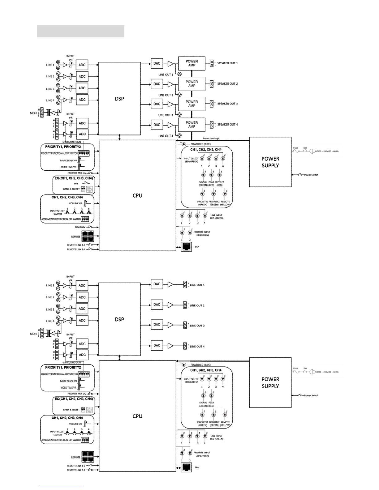
BLOCK DIAGRAM
MA-725F
MM-700F
Page 13
13
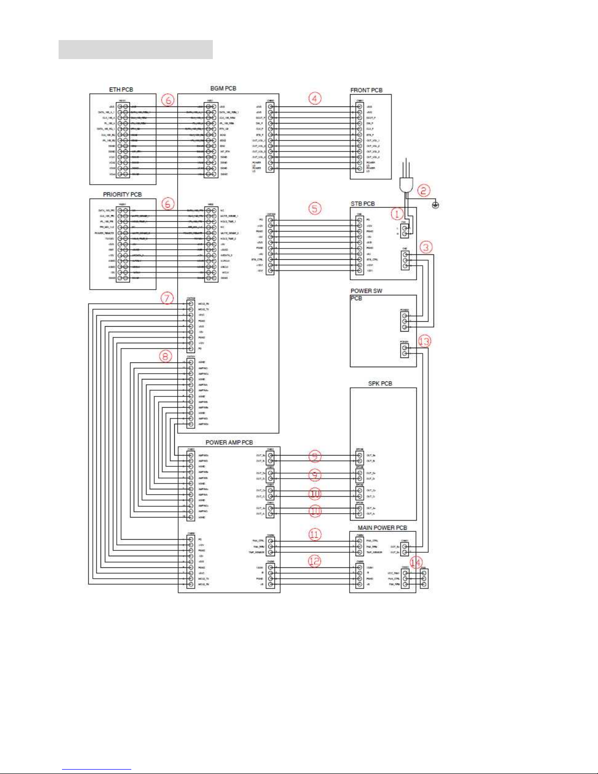
WIRING DIAGRAMS
MA-725F
Page 14
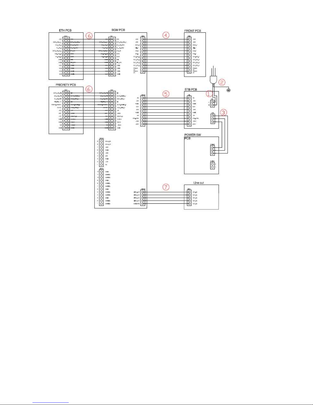
14
MM-700F
Page 15
15
TROUBLESHOOTING
Standard machine startup status and process:
1. Plug in the power, turn on the power switch
2. Blue POWER light is on for lasting 2 seconds
3. CH1. CH2. CH3. CH4 PROTECT red lights are on
4. When the 4 PROTECT red lights are on, the blue POWER light starts to flash 2 times (There is no
PROTECT red light with MM-700F.)
5. Blue POWER flashes to the 2nd time, the internal Relay of the machine is on
6. After the Relay is on for 2 seconds, 4 PROTECT red lights are off, and the INPUT SELECT green light is on.
(There is no PROTECT red light with MM-700F.)
7. Finish the startup.
・At this time, the power consumption of the machine is about 49 W (MM-700F is about 6W)
・Open the top cover and observe the internal light:
Top left corner MA-725F BGM BOARD red LED should be flashing
Lower right corner MA-725F POWER SUPPLY BOARD Red LED should be light constantly
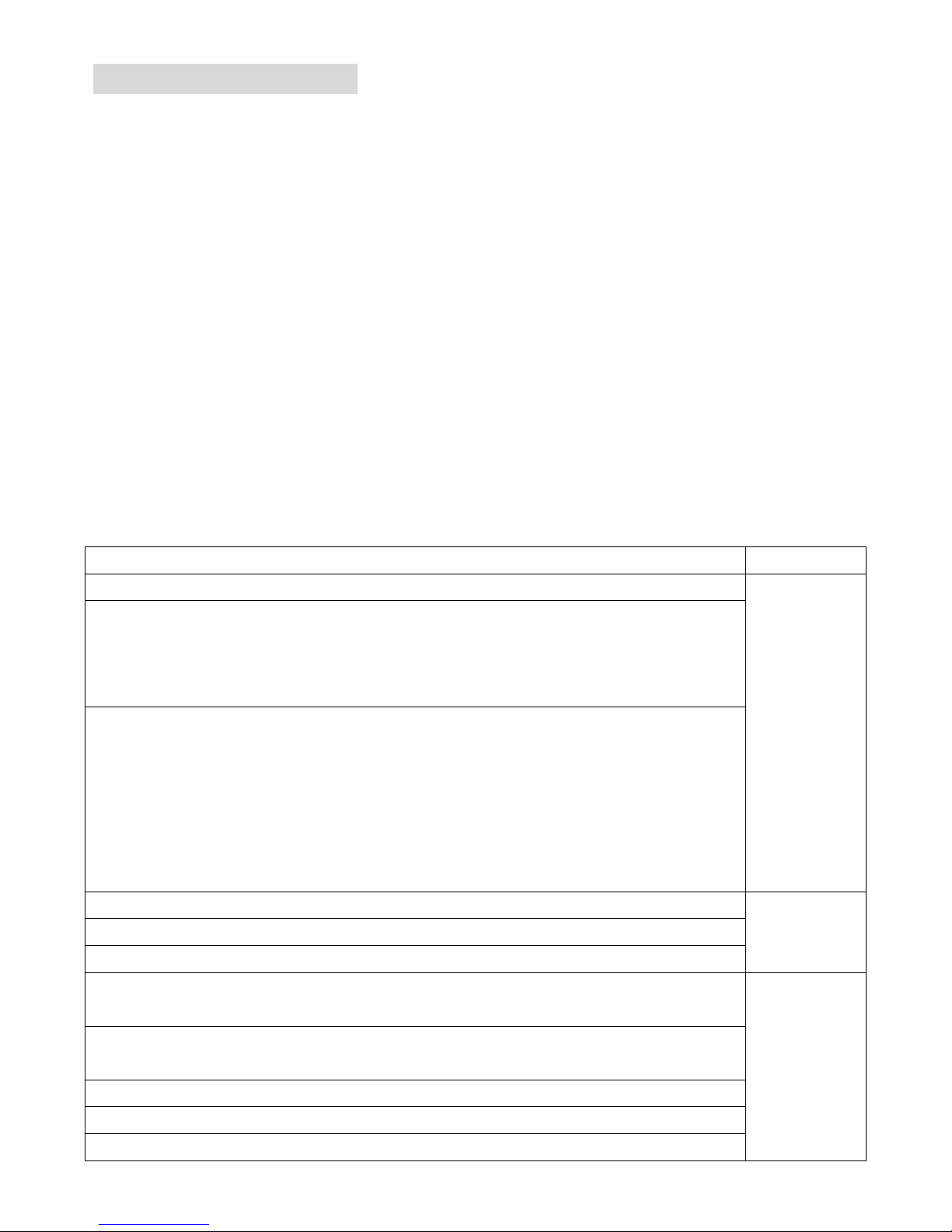
Machine Defective Judgement:
Defective status
NG position
FUSE works, but the blue POWER light is not on after power is on, the machine does not work.
STB PCB
Machine does not work
Remove the rainbow cable from BGM BOARD CN7303:
Measure Pin 5 to chassis voltage: No 3.3V
Measuring Pin7 to chassis voltage: No 5 V
The machine startup process is good, but there is no output with the speaker, POWER SUPPLY
BOARD Red LED is not on:
Remove the red and black lines of the POWER STB BOARD CN202 and measure the voltage
at both ends to be without 16.8V.
Remove the rainbow cable of BGM BOARD CN7303 :
Measure the voltage of Pin2 to the chassis to be without +12V
Measure the voltage of Pin 4 to the chassis to be without -12V
No output after the power is on, BGM BOARD red LED is not on or does not flash continuously
BGM PCB LINE OUTPUT CH1 ~ 4 -no output
MOH ( INPUT 4 ) – no input
The power consumption is correct after the power is on normally. (MA-725F is about 49 W;
MM-700F is about 6W)
PRIORITY
PCB
LINE1~LINE4 input and speaker output are correct
But after input the priority 1.2 signal, the front panel green light is off, no PRIORITY output
Back panel switch to 70V/100V, no response
Back panel switch to HPF1 ~ 4, no response
Back panel switch to POWER REMOTE, no response
Page 16

16
After the power turns on, the blue POWER light does not flash continuously, and the machine
does not work.
ETHERNET
(ETH)
PCB
Back panel REMOTE CH1 ~ 4, no response
Back panel REMOTE LINK CH1-2, CH3-4, no action
Back panel switch to EQ1 ~ 4, no
Connected to the Internet route, the light is not on, fail to connect to the computer. GUI
FUSE OPEN machine no response
Remove POWER SUPPLY BOARD heat sink
Measure Q1A, Q2A, Q8, Q10 to check if any one crystal with a short circuit
MAIN POWER
PCB
Machine is turned on successfully. All front panel PROTECT lights are on. No output.
Measurement CN2 voltage > 16V voltage
But the POWER SUPPLY red LED is off, or blinks
Machine is turned on successfully. All the front panel PROTECT lights are on. No output.
POWER SUPPLY BOARD red LED light is on constantly
Measuring whether the CN5 voltage works
Machine is turned on successfully. All the front panel PROTECT lights are on. No output. Power
consumption < 48W
POWER SUPPLY BOARD red LED is always on, CN5 voltage works.
Measuring the POWER AMP BOARD CN283's rainbow cable
Pin2 has a chassis voltage of +12V
Pin4 has a cabinet voltage of -12 V
POWER AMP
PCB
FUSE OPEN, machine no response
Remove POWER AMP BOARD heat sink
Measure the following crystals to check if any one crystal with a short circuit
Q201, Q201A, Q202, Q202A
Q301, Q301A, Q302, Q302A
Q401, Q401A, Q402, Q402A
Q501, Q501A, Q502, Q502A
Machine is turned on successfully
One or more PROTECT lights of the previous channels lights up and there is no output for this
channel
There are output with other channel
Power consumption < 48W
Page 17

17
MOUNTING DIAGRAMS
■MAIN POWER PCB (Part code : JB00228)
Page 18

18
■Power Amp PCB (Part code : JB00230)
Page 19

19
■BGM+STB+SPK PCB (Part code : JB00229)
BGM PCB
BGM PCB
SPK PCB
STB PCB
Page 20

20
SPK PCB
STB PCB
Page 21

21
■ETH+PRI+Front+SW PCB (Part code : JB00227)
PRI PCB
FRONT PCB
ETH PCB
SW PCB
PRI PCB
FRONT PCB
ETH PCB
SW PCB
Page 22

22
Mechanical parts Part Code
1) Aluminum front panel D012503800
2) Bottom chassis D010600880
3) Top cover D210302380
4) Inner carton D320416250
5) EPE cushion sponge D321104170
6) DC FAN 214AJF0815HA D145100880
Page 23

23
EXPLODED VIEWS AND PARTS LISTS
Page 24

24
Page 25

25
Page 26

26
Page 27

27
Rework SOP
1. STB PCB rework SOP
2. MAIN POWER PCB rework SOP
3. POWER AMP PCB rework SOP
Page 28

1. Open the outer carton and take out the inner carton (Total 2 units)
2. Open the inner carton.
Page 29

3. Take out the unit and remove the side cushions from the unit. Remove the transparent packaging bag.
4. Remove all 14 screws around the unit.
Page 30

5. Lift the cover up.
Page 31

6. Remove the two cables and 3 PCB fixing screws, then remove the upper PCB.
7. Remove 3 PCB fixed copper posts and remove the lower PCB.
Page 32

8. Remove the screw and wire
Page 33

9.Change the new board
Lock the screw and wire
Page 34

10.Put on lower PCB and lock the copper column
11.Put on upper PCB and lock the screw
Install the wire
Page 35

12.Put on cover up and lock the screw
Page 36

1. Open the outer carton and take out the inner carton (Total 2 units)
2. Open the inner carton.
Page 37

3. Take out the unit and remove the side cushions from the unit. Remove the transparent packaging bag.
4. Remove all 11 screws around the unit.
Page 38

5. Lift the cover up.
Page 39

6. Remove the wire,screw and heat sink
Remove the screw and copper column
Page 40

When proceeding the replacement with
SPS board, if there are no copper
columns and washers at these three
circled position, please use the spares
we sent to you to fasten the screws
here.
Please pay attention to the
directions of the two thermal
conductive films. Please do not
exchange the positions after
repairing.
Page 41

7. Change the new board
Lock the copper column,and confirm that the thermal conductive film is still.
Page 42

8.Put on the heat sink,all the screw and wire
Page 43

1. Open the outer carton and take out the inner carton (Total 2 units)
2. Open the inner carton.
Page 44

3. Take out the unit and remove the side cushions from the unit. Remove the transparent packaging bag.
4. Remove all 11 screws around the unit.
Page 45

5. Lift the cover up.
Page 46

6. Remove wire,screw and heat sink
Page 47

7. Remove screw
In case the new vision have to remove two more scew
Page 48

8.Change the new board
Put the four thermal conductive film on the MOSFET
Page 49

Apply thermal grease to the circle
pointed position and lock the heat sink.
The thermal grease needs to cover the
thermistor and foam.
Please take notice that these thermal
conductive films can not be damaged
during the repairing process.
Page 50

9.Put on heat sink and all the sink and screw
 Loading...