

Page 1

SOFTWARE INSTRUCTIONS
MIXER AMPLIFIER A-5000 SERIES
(Ver. 1.0.0)
Thank you for purchasing TOA’s Mixer Amplier.
Please carefully follow the instructions in this manual to ensure long, trouble-free use of your equipment.
Page 2

TABLE OF CONTENTS
1. A-5000 PC SOFTWARE OUTLINE
1.1. General Description ............................................................................................... 4
1.2. System Requirements ........................................................................................... 4
........................................................ 4
2. SOFTWARE SETUP ........................................................................................ 6
2.1. Installing the A-5000 PC Software ........................................................................ 6
2.2. Uninstalling the A-5000 PC Software ................................................................... 8
3. SETTINGS FLOW ............................................................................................. 8
4. STARTING THE SOFTWARE .................................................................... 9
4.1. Starting from the “Start” Menu .............................................................................. 9
4.2. Starting from the Shortcut Icon ............................................................................. 9
5. MOVING FROM THE INITIAL OPERATION SELECTION
SCREEN TO THE MAIN SCREEN
....................................................... 10
6. MAIN SCREEN AND INDIVIDUAL VIEWS ..................................... 13
6.1. Menu View ........................................................................................................... 14
6.2. Status View ......................................................................................................... 15
6.3. Flow View ............................................................................................................ 17
7. UNIT AND CHANNEL NAME SETTINGS ........................................ 19
8. INPUT AND OUTPUT LEVEL MONITORING
(Only possible in online mode.) ................................................................................... 20
9. SIGNAL PROCESSING DETAILED SETTINGS .......................... 21
9.1. Basic Function Box Operation in Flow View ........................................................ 21
9.2. Compression Settings ......................................................................................... 22
9.3. Manual Mute Settings ......................................................................................... 23
9.4. Master Volume Settings ...................................................................................... 26
9.5. PEQ Settings ....................................................................................................... 27
10. PRESET MEMORY-RELATED SETTINGS AND
OPERATIONS ................................................................................................. 29
10.1. What Is the Preset Memory? ............................................................................. 29
10.2. Preset Memory Name Settings ......................................................................... 29
10.3. Setting the Preset Memory Number To Be Called Up When Power Is
Switched On ...................................................................................................... 30
10.4. Changing the Preset Memory Number To Be Called Up .................................. 31
10.5. Storing Set Parameters in Preset Memory ....................................................... 32
11. COMMUNICATION SETTINGS ............................................................ 33
11.1. Connections between the PC and the Unit ........................................................ 33
11.2. Method to Enable Communications between the PC and the Unit ................... 33
11.3. Connection Settings .......................................................................................... 34
11.4. Communications ................................................................................................ 37
12. GLOSSARY ...................................................................................................... 39
12.1. PC Software Screen .......................................................................................... 39
2
Page 3

12.2. Signal Processing Function .............................................................................. 39
12.3. System Function ............................................................................................... 40
12.4. Communication Related Terms ......................................................................... 40
12.5. External Control Functions ................................................................................ 40
12.6. Maintenance Function ....................................................................................... 40
13. SPECIFICATIONS ........................................................................................ 41
13.1. Software Specification ....................................................................................... 41
13.2. Setting/Display Items, Setting Ranges, and Default Settings ........................... 41
3
Page 4

1. A-5000 PC SOFTWARE OUTLINE
1.1. General Description
Use the dedicated settings software when setting compression and manual mute functions for the A-5000
Series.
Settings can be performed regardless of whether the A-5000 series (referred to as “unit” hereinafter) is
concurrently in communication with a PC (online mode) or not (ofine mode).
Note, however, that some operations and displays can only be performed online.
The PC and unit communicate via a network. When both are online, Preset Memory can be recalled from the
PC to the unit, and acoustic signal processing settings can be changed in real time. Only one unit at a time can
be used with the PC software.
Set data can be stored in the PC.
1.2. System Requirements
Install the software in a PC that meets the following specications:
1.2.1. Recommended PC requirements
Hardware Requirements
CPU Intel Core
Memory Over 2 GB
Display 1024 x 768 resolution or higher
Free Hard Disk Space Over 16 MB
however, over 600 MB is required for the 32 bit version or over 1.5 GB for the 64
bit version when “.NET Framework” is not yet installed
Optical Drive CD-ROM drive
LAN 10 0 BASE-T X
Software Requirements
OS Following are the veried operating systems:
Windows 7 Professional 32bit SP1
Windows 7 Professional 64bit SP1
Windows 8.1 Pro 32bit
Windows 8.1 Pro 64bit
Required Component .NET Framework 4 Client Prole (Internet access is required when “.NET
Framework” needs to be installed)
TM
i3, 2 GHz or faster
• Intel Core is the trademark of Intel Corporation in the United States and other countries.
• Windows is the registered trademarks of Microsoft Corporation in the United States and other countries.
• Regarding other company names and products, they are also trademarks of individual companies.
4
Page 5
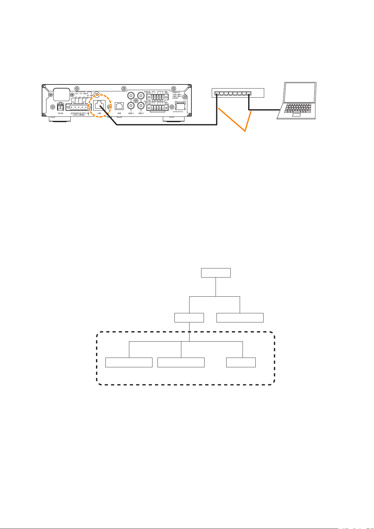
1.2.2. Connecting between the PC and the unit
Connect the unit’s LAN terminal to the PC via a switching hub.
Connect a PC and the unit to a switching hub using LAN straight-through cables individually.
PC with the A-5000 PC
Software installed
A-5006/5012
LAN terminal
Switching hub
Category 5 or higher shielded twisted
pair straight-through cable for LAN
(with RJ45 connectors)
1.2.3. Network
• Perform the network setting for the PC in advance following the instructions of the network administrator of
the facilities where the unit is installed.
If incorrect setting has been performed, this may adversely affect other devices connected to the same
network.
• The unit that communicates with this software can be detected using the Device detection function.
The Device detection function detects the unit connected on the local area network.
A “Broadcast” communication method is used for detection.
Therefore, this detection function is available only within the effective range of broadcast. Broadcast will not
reach beyond the router even within the local area network.
Router
Router
A-5000 series (1)
Effective range of broadcast (Device detection possible from a PC.)
A-5000 series (2)
A-5000 series (3)
PC
In the network conguration shown above, the A-5000 series (3) cannot be detected if the device detection
is executed from the PC.
For the effective range of broadcast, consult your network administrator of the facilities where the unit is
installed.
5
Page 6
2. SOFTWARE SETUP
2.1. Installing the A-5000 PC Software
Terminate all other application programs in operation before installation.
Follow the procedures below to install.
Step 1. Insert the supplied CD into the PC’s CD drive.
Step 2. Open the CD drive from the “Explorer” or “My Computer.”
The “English” folder, “Japanese” folder, and other contents are displayed.
Step 3. Open the “English” folder.
Step 4. Open the “Software” folder.
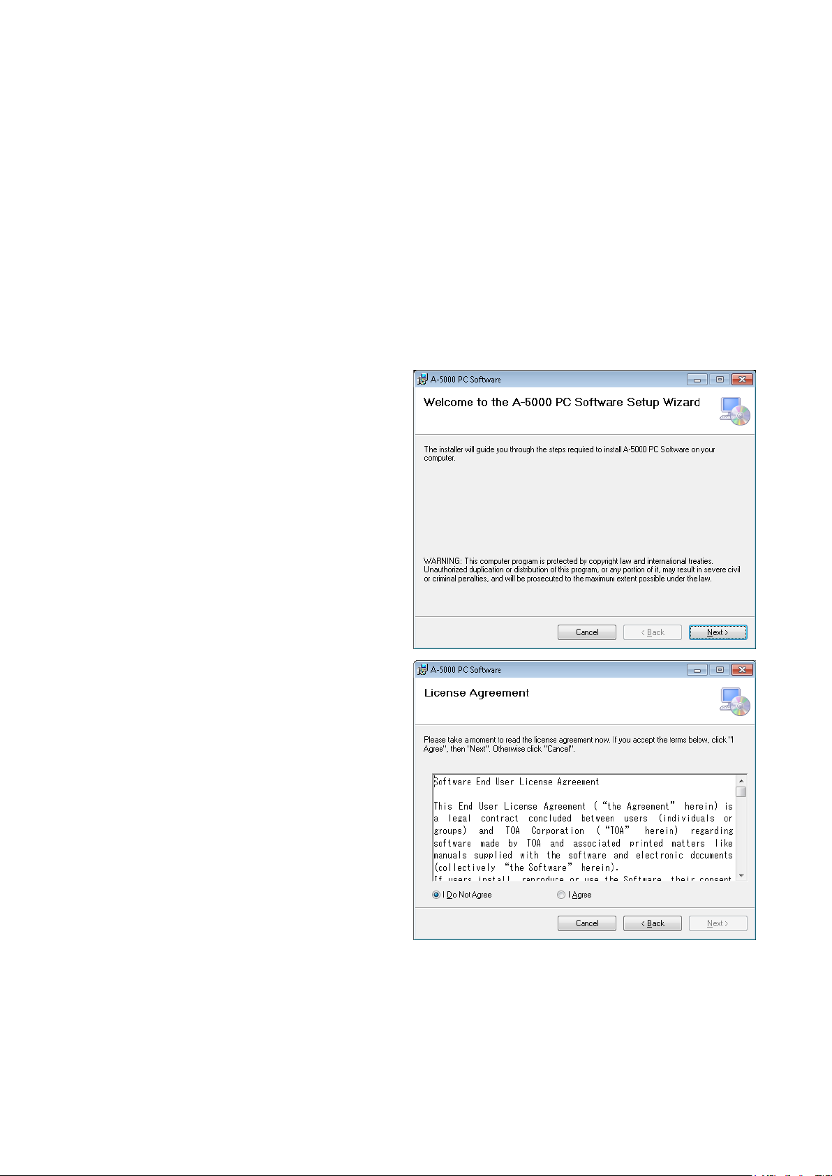
Step 5. Double-click the “setup.exe.”
The window at right is displayed.
Step 6. Click the [Next] button.
The window at right is displayed.
Check the contents of the License
Agreement, then choose the “I Agree” or “I
Do Not Agree” radio button.
Choosing “I Agree” allows to click the [Next]
button.
Step 7. Check the contents of the window, then
click the [Next] button.
6
Page 7
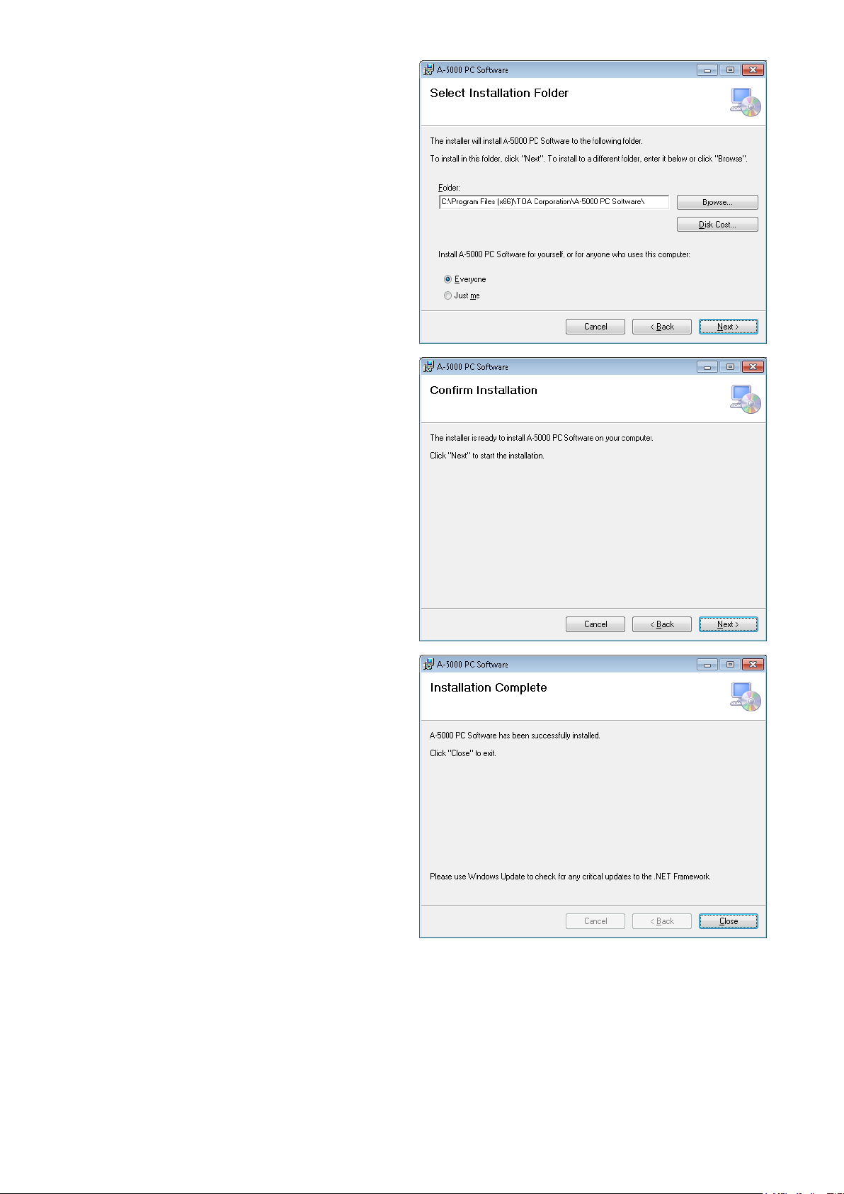
The window at right is displayed.
Step 8. If necessary, change the folder into which
the software will be installed, then click the
[Next] button.
The window at right is displayed.
Step 9. Start installation according to the
instructions on the screen.
Tip
If the .NET Framework is not installed in the PC, follow the on-screen instructions to install it.
Connection to the internet is required.
Step 10. Click the [Close] button after installation completion.
The shortcut icon for the A-5000 GUI executable program is stored in the PC’s start menu.
7
Page 8
2.2. Uninstalling the A-5000 PC Software
Step 1. Click the Start button on the PC’s desktop, and select [Setting Control Panel].
The “Control Panel” window is displayed.
Step 2. Double-click the “Programs and Features” icon.
The currently installed program will then be displayed.
Step 3. Select “A-5000 PC Software.”
Step 4. Click the “Uninstall.”
The A-5000 PC Software is uninstalled.
3. SETTINGS FLOW
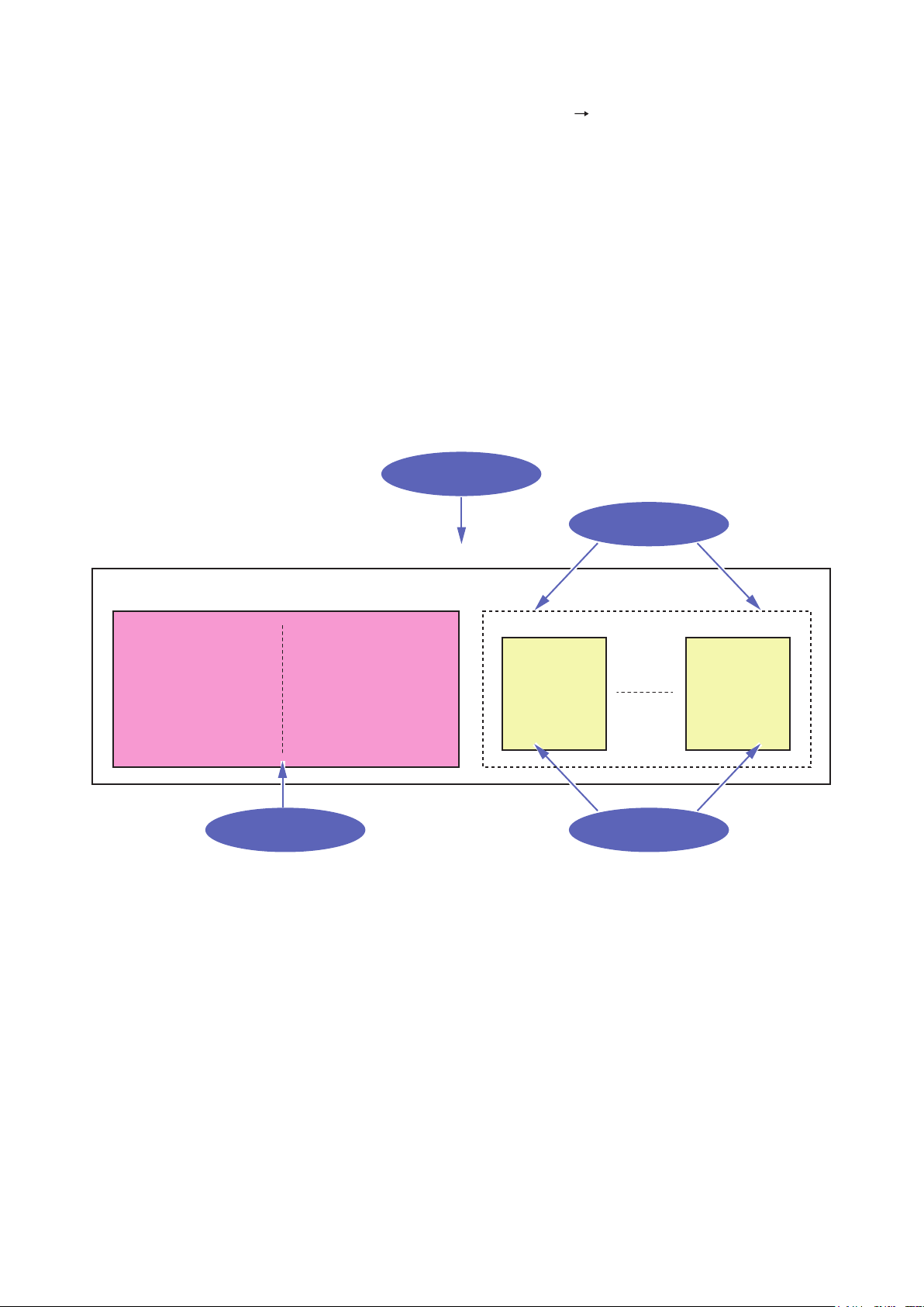
[Settings Summary]
Settings contents are broadly divided into preset memory parameter (see p. 30), where signal processing
parameters are stored, and static parameter, for parameters not stored in the preset memory.
Use the Menu
View to store.
Use the Memory
View to store.
Setting file
Static parameter (Settings other than preset memory) Preset memory parameter
IP address
Subnet mask
Default gateway
DHCP
Unit name
Channel name
Preset memory name
Primary reference preset
memory number
Use the Menu
View to set.
Preset memory 1 Preset memory 16
PEQ
Compressor
Mute
Master volume
Use the Flow
View to set.
[Setting procedure example]
Step 1. Install the unit and set it up for audio output.
Step 2. Connect the unit to a PC (see p. 5).
Step 3. Install the A-5000 PC Software in the PC and start it (see p. 6 and p. 9).
Step 4. Receive date from unit and display its settings on the main screen (see p. 11).
PEQ
Compressor
Mute
Master volume
Step 5. Set both unit and channel names (see p. 19).
Step 6. Set preset memory names and the preset memory number to be displayed when power is switched on
(p. 29 and 30).
Step 7. Perform more detailed settings on the Flow View, actually outputting audio (see p. 21).
Step 8. Save settings to the preset memory (p. 32).
Step 9. Call up a different number of preset memory and repeat Steps 6 – 8.
8
Page 9

4. STARTING THE SOFTWARE
The following two different methods are available for starting the installed A-5000 PC Software:
4.1. Starting from the “Start” Menu
You can start the A-5000 PC Software from the start menu.
Click the Start button on the PC’s desktop, and select [Programs TOA Digital Audio Control A-5000 PC
Software] to start.
4.2. Starting from the Shortcut Icon
You can start the A-5000 PC Software by double-clicking the shortcut icon created on the desktop
after installation completion.
9
Page 10

5. MOVING FROM THE INITIAL OPERATION SELECTION SCREEN TO
THE MAIN SCREEN
Connect the A-5000 Series unit to a PC and perform settings, actually outputting audio.
Starting up the A-5000 PC Software displays the initial operation selection screen. Select from among [File
New], [File Open], and [Connect] depending on the type of work to be done.
1
1. File New
Select this key to create a new setting le.
Clicking this key switches the screen display to the main screen (see p. 13).
2. File Open
Select this key to open a previously created settings le.
Clicking this key displays the “Open” dialog box.
Select the desired le (extension: a5d) and click the [Open] button.
File is opened, and the screen display is switched to the main screen (see p. 13).
2 3
10
Page 11
3. Connect
Select this key to receive the A-5000 Series unit’s setting data via the LAN port and display it on the A-5000
PC Software’s setting screen. Be sure the A-5000 unit is connected to the PC in advance by way of a
switching hub (see p. 33.)
[Receiving Data]
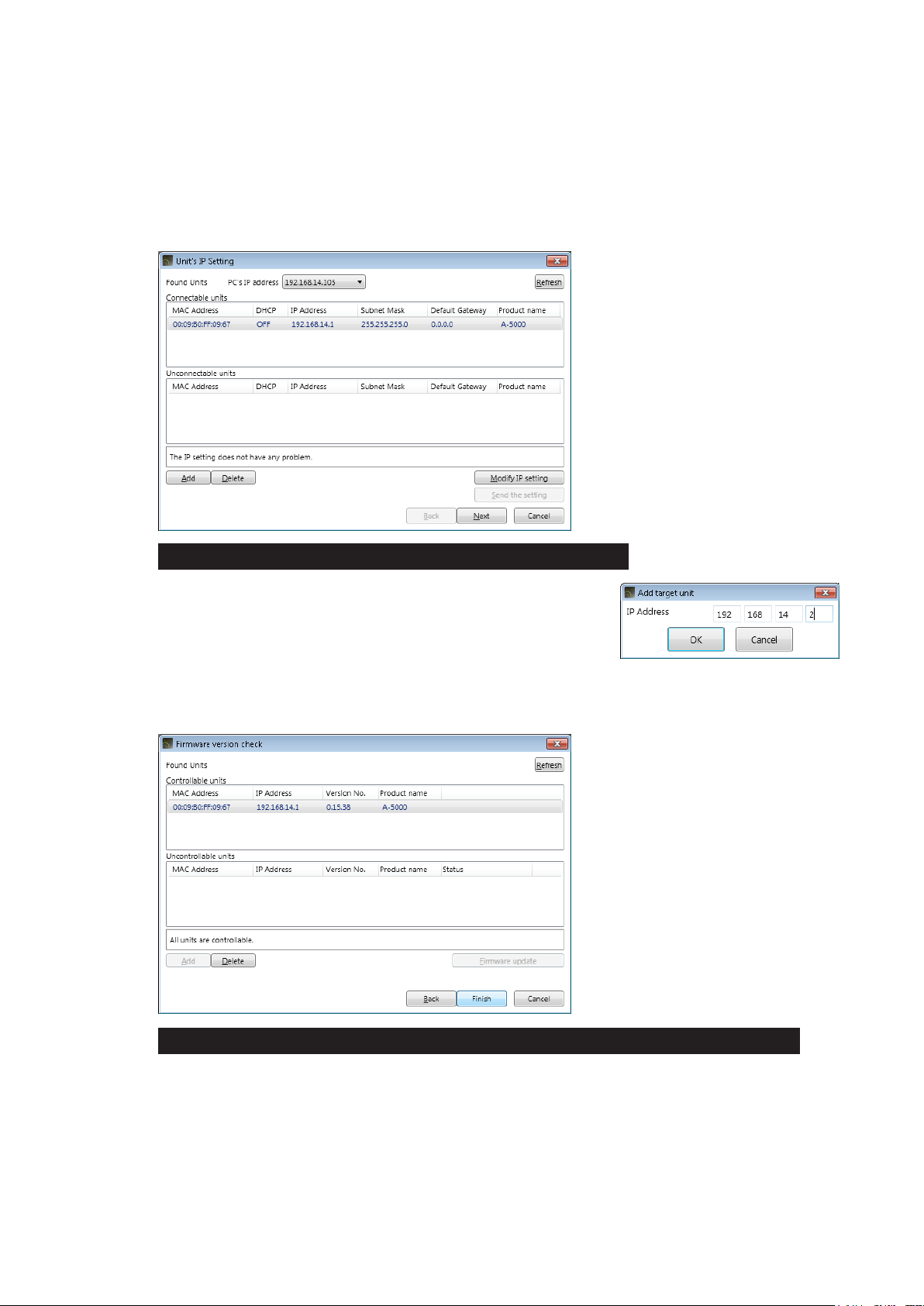
Step 1. Click the [Connect] button on the initial operation selection screen.
Units are automatically detected and the Unit’s IP Setting screen is displayed.
When the desired unit from which to receive data is not displayed:
The unit is not displayed in the above screen when connected
via a router. Use the [Add] button to add the unit. If the [Add]
button is clicked, the Add target unit screen (shown at right) for
connected units is displayed. Enter the IP address of the desired
connected unit.
Step 2. Select the desired unit from which to receive data, then click the [Next] button.
The Firmware version check screen is displayed.
When the desired unit from which to receive data is listed among “Uncontrollable units” :
As the rmware version may be old and out of date, update the rmware using the [Firmware update]
button. (See p. 36, Step 6 of “Connection Settings.”) Once the rmware is updated, the unit
should then be displayed among the “Controllable units.”
Step 3. Select the desired unit from among the “Controllable units” and click the [Finish] button.
11
Page 12
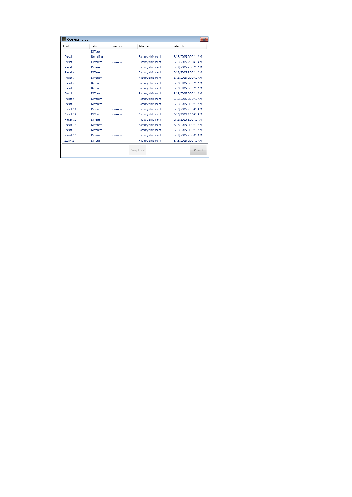
Data reception is started and the Communication screen is displayed.
Tips
• Reception status is displayed in the Communication screen. (See p. 40 “Preset,” “Static.”)
• The display reverts to the initial operation selection screen if the [Cancel] button is clicked.
Step 4. Click the [Completed] button.
The screen display is switched to the main screen (see p. 13).
12
Page 13
6. MAIN SCREEN AND INDIVIDUAL VIEWS
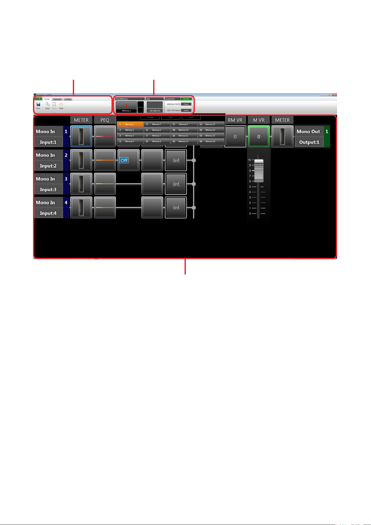
After initial operation selection settings, the Main screen is displayed.
The main screen consists of the Menu View, Status View and Flow View.
Menu View Status View
Flow View
13
Page 14
6.1. Menu View
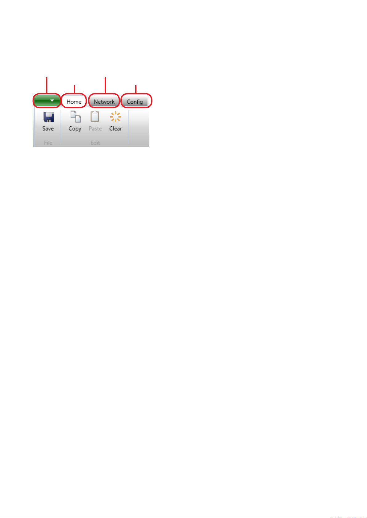
The Menu view is located in the upper left section of the Main screen.
Clicking on the individual tabs in the Menu view displays the menu icons related to each corresponding function.
Click on a menu icon to execute its function.
Application tab
Home tab Cong tab
Note: Clicking the ALT key displays the shortcut keys of the ribbon menu.
6.1.1. Application
New: Creates (sets) a new data le.
Open... : Calls up the existing data le.
Save: Overwrites the le being edited.
Save As... : Saves the le being edited to the disk under a different name.
Close: Closes the le being edited.
About... : Displays the A-5000 PC Software version number.
Exit: Exits the A-5000 PC Software.
6.1.2. Home
Network tab
Save: Updates the le being edited.
Copy: Copies the value set for the function box selected on the ow view (see p. 17) to the clipboard.
Paste: Pastes the data in clipboard to the function box selected on the ow view.
Clear: Initializes the value set for the function box selected on the ow view.
6.1.3. Network
Connect: Connects the unit to a PC for online processing. (See p. 33.)
Disconnect: Disconnects the unit from a PC for ofine processing. (See p. 38.)
Tip
The unit’s setting does not change while in the ofine state even if it is changed with a PC.
Connection Setting: Allows you to perform network settings and to designate the unit’s IP address to which this
software can access.
Auto Connect: Makes an automatic connection when the le is opened next time.
6.1.4. Config
Name: Displays the unit name setting dialog. (See p. 19.)
Preset Memory Setting: Displays the preset memory setting dialog. (See p. 29.)
14
Page 15
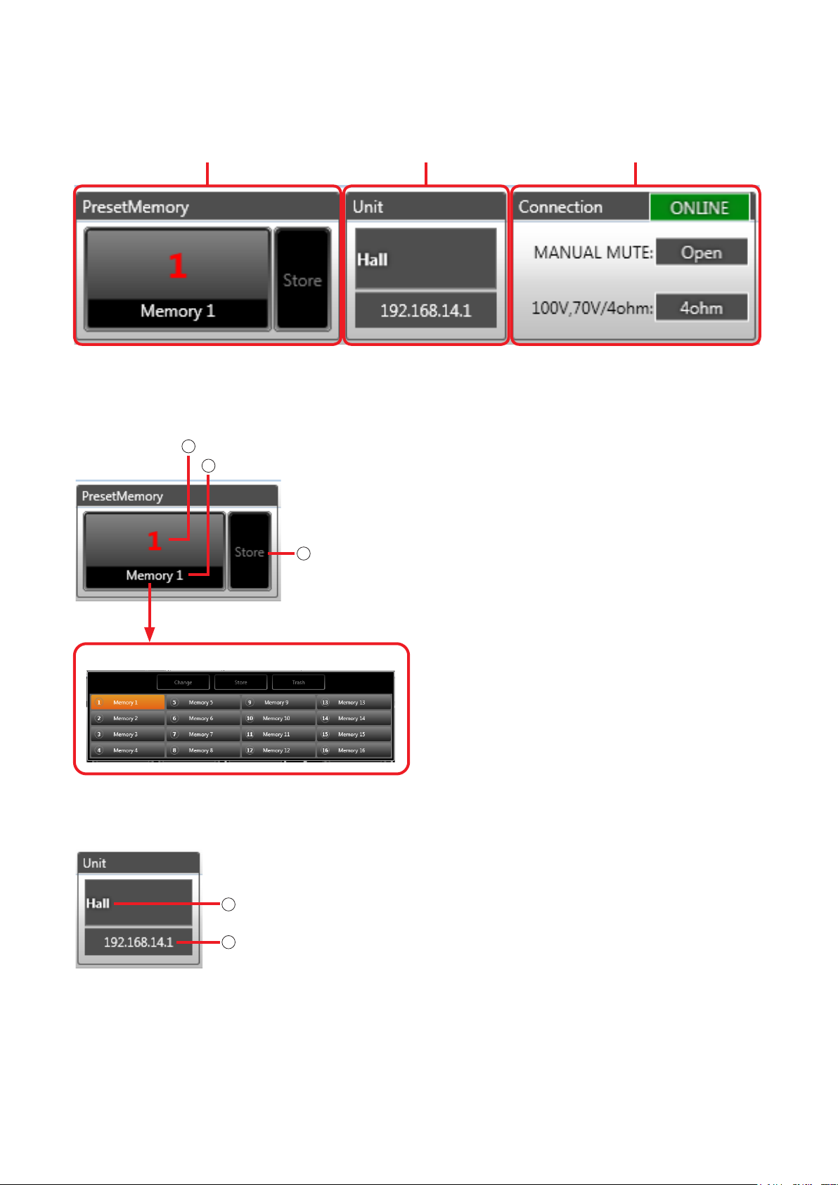
6.2. Status View
The Status view is located in the upper right section of the Main screen.
The Status view consists of Memory, Unit and Connection views.
Memory View Unit View Connection View
The Status view displays information related to the unit to be set.
6.2.1. Memory view
1
Preset memory number
2
Preset memory name
1. Preset memory number
Displays the number of the currently selected
Preset Memory (see p. 29).
Click this button to display the Memory List panel.
Click this button.
[Memory list panel]
6.2.2. Unit view
1
Unit name
2
Unit IP address
3
Store button
2. Preset memory name
Displays the name of the currently selected Preset
Memory (see p. 29).
Click this button to display the Memory List panel.
3. Store button
If this button is clicked, the contents set in the Flow
View can be written to the currently selected preset
memory.
1. Unit name
Unit’s name is displayed.
The unit name can be set from the Menu View’s
“Cong” tab (see p. 19).
2. Unit IP address
Unit’s IP address is displayed.
For the unit’s IP address, please read “Connection
Settings” in “Communication Settings” on p. 34.
15
Page 16
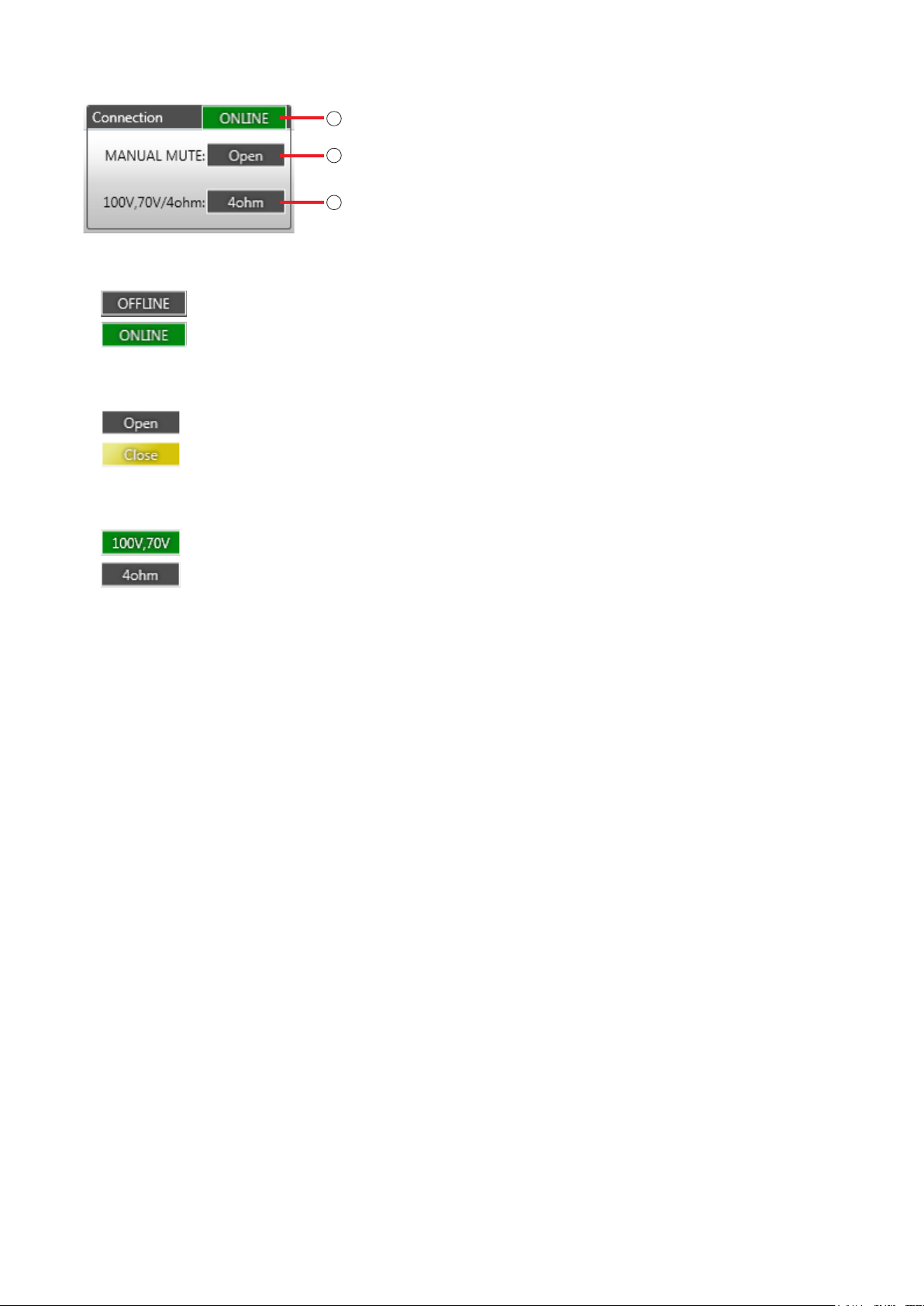
6.2.3. Connection view
1
Unit communication connection status display
2
Manual mute terminal status
3
Impedance setting status
1. Unit communication connection status display
Displays the status of communication with the unit.
: Unconnected (ofine status)
: Connected (online status)
2. Manual mute terminal status
Displays the manual mute terminal status.
: Open
: Close (muted)
3. Impedance setting status (status of DIP SW4 on the unit’s rear panel)
Displays the impedance setting status.
: High impedance 100 V line or 70 V line (100 V, 70 V)
: Low impedance (4 Ω)
16
Page 17
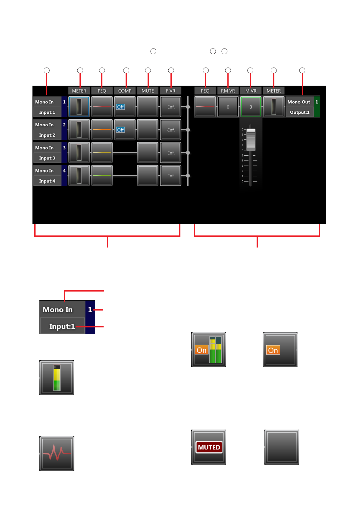
6.3. Flow View
Displays the unit’s signal processing image.
The Flow View consists of Level Meter boxes 2 and Func t ion bo x e s
functions.
3
– 8 that show the unit’s signal processing
1 1
2 23 34 5 6 7 8
Signal input (monaural input: 4 channels) Signal output (monaural output: 1 channel)
1. Channel information
Displays the input or output channel number and
the channel name.
Input or output
Channel number
Channel name
2. Level meter (only displayed when in online mode)
Displays the level of each input and output.
(For details, see p. 20.)
3. PEQ (Parametric Equalizer)
Roughly displays the frequency characteristics
curve set with the PEQ.
Frequency characteristics are indicated by a at
straight line when all gains are set to 0 dB.
(For details, see p. 27.)
4. Compressor
These function boxes are only for monaural
inputs 1 and 2, and display the On/Off status of
compression settings and input and output levels.
(When in online mode) (When in ofine mode)
5. Mute
Displays muting status.
The display is as shown below while muting is
enabled.
(When in online mode
and muting is activated)
(When in ofine mode
or muting inactivated
when in online mode)
(For details, see p. 23.)
17
Page 18
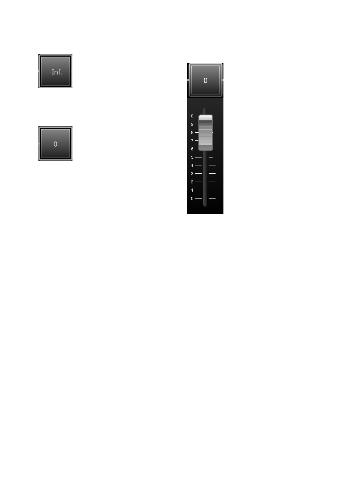
6. Front panel-mounted volume control (only
displayed when in online mode)
Displays the gain value of the volume control on
the front panel.
7. Remote master volume control (only displayed
when in online mode)
Displays the gain value of the remote master
volume output.
8. Master volume control
Allows operation of the master volume fader. The
master volume’s gain value display (shown in the
upper part of the fader) is interlocked with the fader
position.
(For details, see p. 26.)
18
Page 19
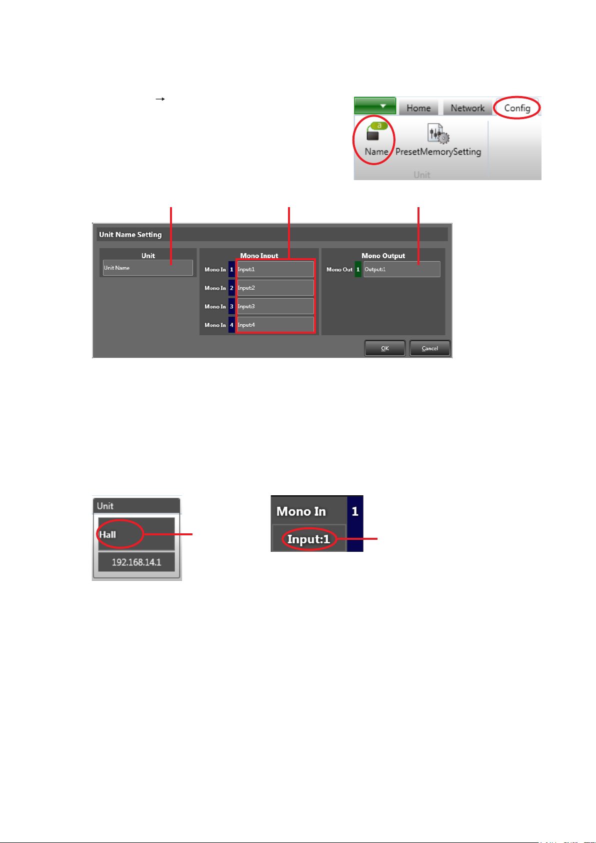
7. UNIT AND CHANNEL NAME SETTINGS
Set the names of units and each channel of monaural input and output.
Step 1. Select [Cong Name] in the Menu View.
The Unit Name Setting screen is displayed.
Unit name Monaural input channel name Monaural output channel name
Step 2. Click a name box to enter a name.
Each name must be within 20 characters in length.
Step. 3. Click the [OK] button.
The name is set and reected in both Unit View and Flow View.
[Unit View] [Flow View] (channel information display)
Unit name
Channel name
19
Page 20
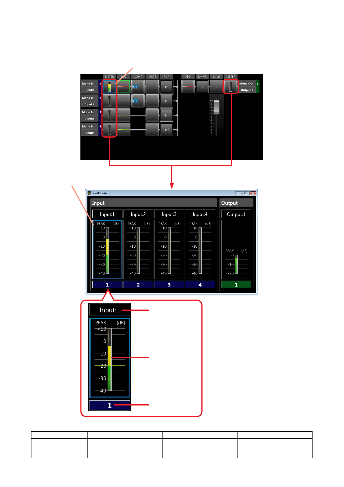
8. INPUT AND OUTPUT LEVEL MONITORING (Only possible in online mode.)
When in online mode, clicking one of the level meter boxes displayed in Flow View displays the details of the
level meters of all channels.
[Flow View]
Clicked boxes are highlighted by a blue frame.
The level meter corresponding to the clicked box is
displayed surrounded by a blue frame.
Click the Level Meter box.
Channel Name
Level Meter
Channel Number
The level meter displays signal levels in a bar graph.
Set the unit for operation within a level range that is not displayed in red.
Channel Classication Mono In 1 & 2 Mono In 3 & 4 Mono Out
Signal Level +7 dB to +10 dB (peak): Red
−20 dB to +7 dB: Yellow
Under −20 dB: Green
+7 dB to +10 dB (peak): Red
−10 dB to +7 dB: Yellow
Under −10 dB: Green
0 dB to +3 dB (peak): Red
Under 0 dB: Green
20
Page 21
9. SIGNAL PROCESSING DETAILED SETTINGS
9.1. Basic Function Box Operation in Flow View
9.1.1. Display the Detailed Settings View to preform settings
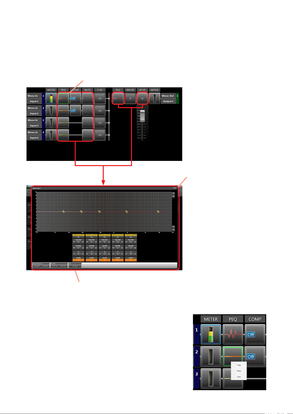
Clicking on a signal processing function box in Flow View displays the Detailed Settings View, allowing changes
in setting.
[Flow View]
The clicked box is highlighted by a green frame.
Step 1. Click the function box.
Step 3. Click the [Close] button or
outside the Detailed Settings
View.
The Detailed Settings View
is closed.
Step 2. Change the setting on the Detailed Settings View.
9.1.2. Perform settings using the right-click menu or drag & drop
The following operations can be performed for each function box using the
menu displayed by right-clicking the box.
Data can be copied and pasted by dragging and dropping the box.
Copy: Copies the parameters set for the function box selected on the
operation view to the clipboard.
Paste: Pastes the data in clipboard to the function box selected on the
operation view.
Clear: Initializes the parameters set for the function box selected on the
operation view.
21
Page 22
9.2. Compression Settings
9.2.1. What is compression?
Compression is a function that reduces the volume of an input signal when there is an excessive signal input.
When an input signal exceeds the set threshold level, this function compresses the excessive sound volume
to a predetermined ratio and controls the signal by means of a predetermined attack time (see p. 39). This
function is used to prevent clipping distortion and damage to speakers.
9.2.2. Setting compression
Compression can be set for input channels 1 and 2.
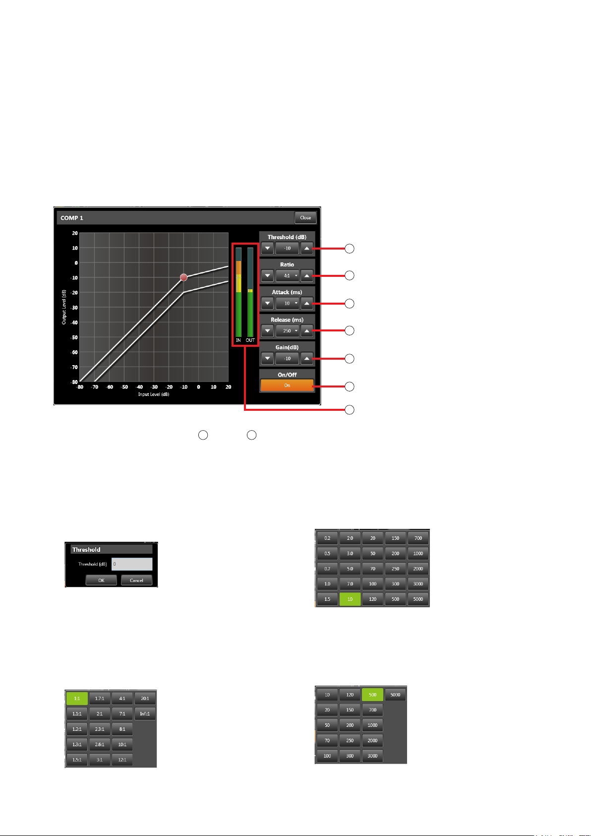
In Flow View, click the Compression box, displaying the Detailed Compression Settings for the selected channel.
1
Threshold
Compression ratio
2
3
Attack time
Release time
4
Gain
5
6
On/Off button
7
Input and output level meters
1
The numerical values of settings
the DOWN button. Clicking the central button opens the Settings dialog box. Settings are performed by either
directly entering values or selecting given values.
1. Threshold
Sets the threshold value. Compression is performed
on input signals that have a higher input level than
the value set here.
[Threshold Settings dialog box]
2. Compression ratio
Sets the “input level increment to output level
increment” compression ratio for the input signal.
When compression is disabled, the ratio is “1:1”.
The compression rate increases in steps of “1.1:1”,
“1.2:1”….. with maximum compression at “Inf.:1”.
[Compression Ratio Setting dialog box]
through
5
above can be increased with the UP button and decreased with
3. Attack time
Sets the reaction time (unit: ms) for compression to
be initiated when excessive input is detected.
[Attack Time Settings dialog box]
4. Release time
Sets the response time (unit: ms) for release of
compression after the input signal drops to below
the threshold level.
[Release Time Settings dialog box]
22
Page 23
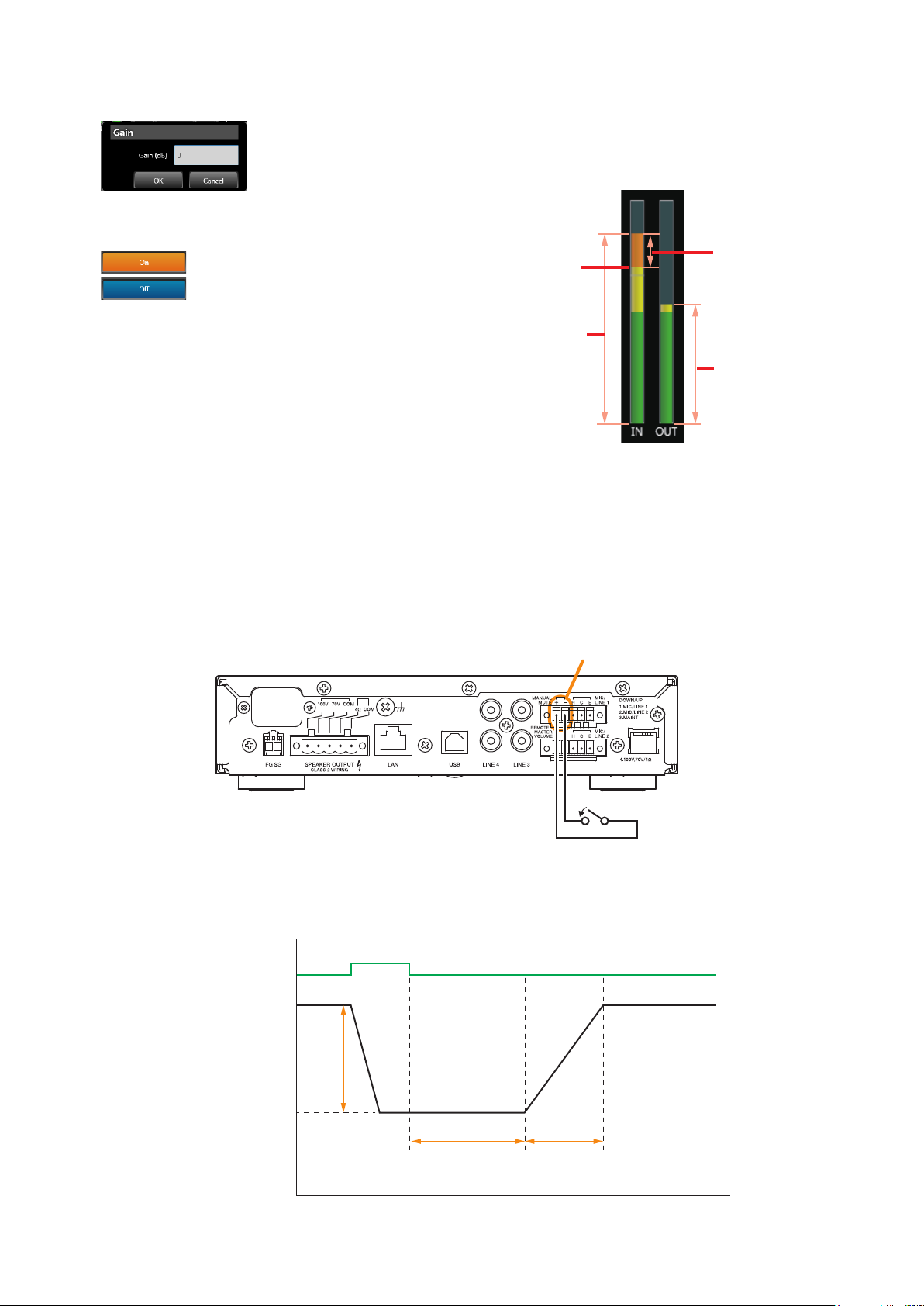
5. Gain
Sets an amplication factor.
[Gain Settings dialog box]
6. On/Off button
Sets to enable or disable compression.
: Compression enabled.
: Compression disabled.
7. Input and output level meters
When communication is in progress between the
unit and PC, the input and output signal levels,
reduction level (effective degree of compression)
and threshold level are displayed in the bar graph
as shown below:
Reduction level
Threshold level
Input signal level
Output signal level
9.3. Manual Mute Settings
9.3.1. What is manual mute?
Manual Mute is used to attenuate the input signal to the A-5000 Series unit. When the Manual Mute terminals
are closed, the audio of the selected input is attenuated.
Manual mute terminal
A-5006/5012
Close the terminal.
The reduction level (attenuation), hold time (time the audio attenuation is retained after being triggered) and
fade-in time (time required to return to the unattenuated volume) can be independently set for each input.
Trigger
(Closes the Manual
Mute terminals.)
Attenuation
(dB)
0
–10
–20
–30
–40
–50
–60
–70
Reduction level
Hold time Fade-in time
Time (sec)
23
Page 24
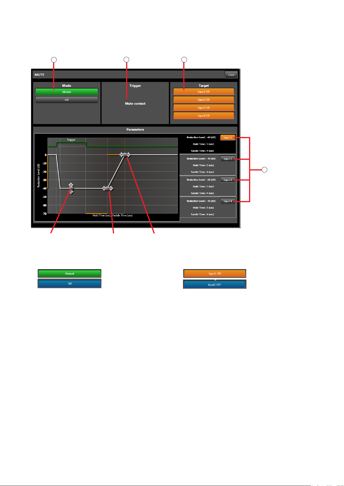
9.3.2. Setting manual mute
Set manual mute for each input channel (1 – 4). (Refer to the next page for setting procedures.) Clicking the
Mute box in the Flow View displays the Manual Mute Detailed Settings View.
1
Mode
2
Trigger Target
3
Input selection
4
Reduction level point Hold time point Fade-in time point
1. Mode
Used to set to enable or disable Manual Mute.
: Mute enabled.
: Mute disabled.
• If set to “Manual”:
When the Manual Mute terminals on the rear
panel receive a contact input, the audio of the
input channel set to Target-ON is muted. The
mute status is displayed in the Mute box (p. 17)
of the Flow View.
• If set to “Off”:
Manual Mute is disabled.
2. Trigger
Displays the Mute activation trigger.
• If Mode is set to “Manual”:
The indication “Mute contact” is displayed. The
contact input to the unit’s rear panel-mounted
Manual Mute terminals is a mute trigger.
3. Tar g e t
Selects the input to be muted.
4. Input selection
Used to set the following parameters individually
for each input:
• Reduction level
Sets the attenuation level. To set the level, drag
the reduction level point up or down.
• Hold time
Sets the hold time by dragging the hold time point
right or left.
• Fade-in time
Sets the fade-in time by dragging the fade-in time
point right or left.
: The channel is muted.
: The channel is not muted.
• If Mode is set to “Off”:
Nothing is displayed.
24
Page 25
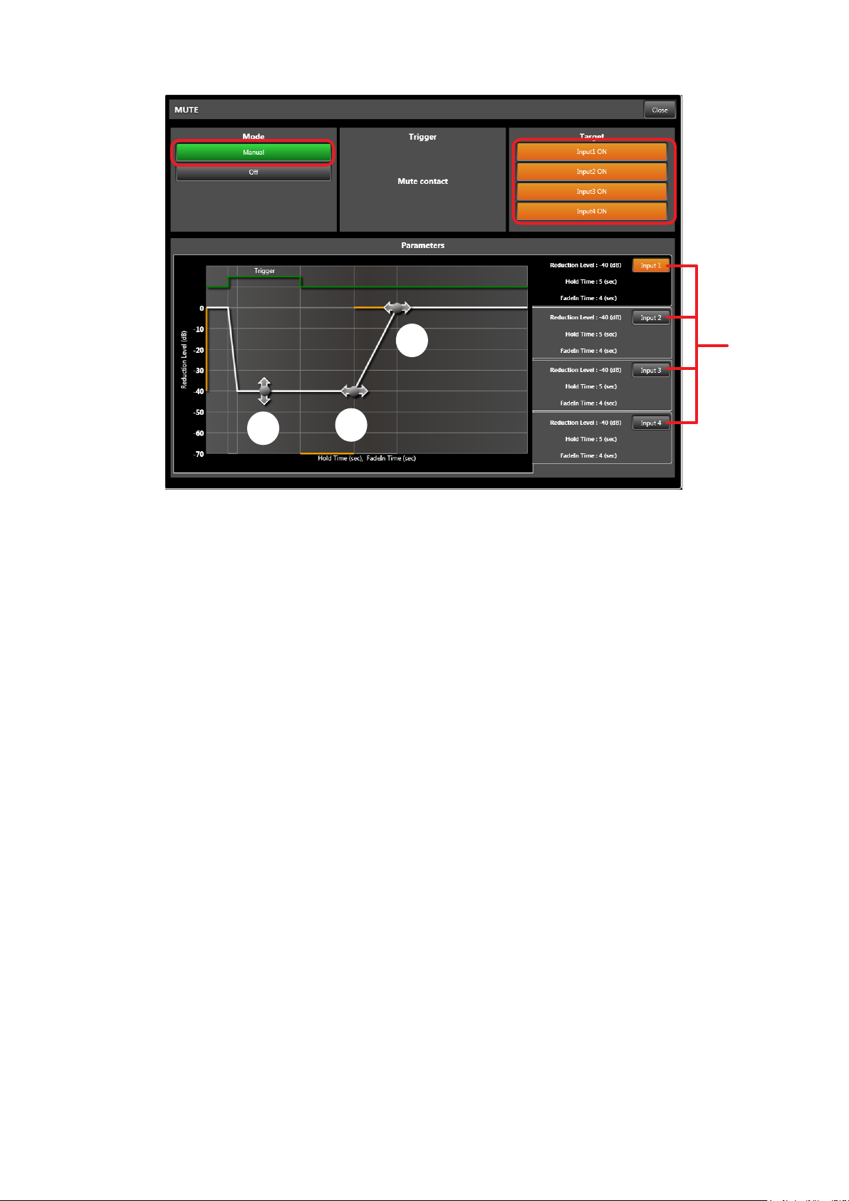
[Setting Procedures]
1
2
6
4
Step 1. Click the [Manual] button.
The button lights green, enabling the Mute function.
The indication “Mute contact” is displayed in the Trigger eld.
Step 2. Click the input that uses the Manual Mute function.
The clicked input button lights orange, indicating that input can be muted. Multiple inputs can be
selected.
Step 3. Click the input button for which detailed parameters are set.
The detailed settings for the clicked input are displayed graphically.
Step 4. Set the reduction level by dragging the reduction level point up or down.
Step 5. Set the hold time by dragging the hold time point right or left.
5
3
Step 6. Set the fade-in time by dragging the fade-in time point right or left.
Step 7. Repeat Steps 3 – 6 to perform settings for all targeted inputs.
25
Page 26
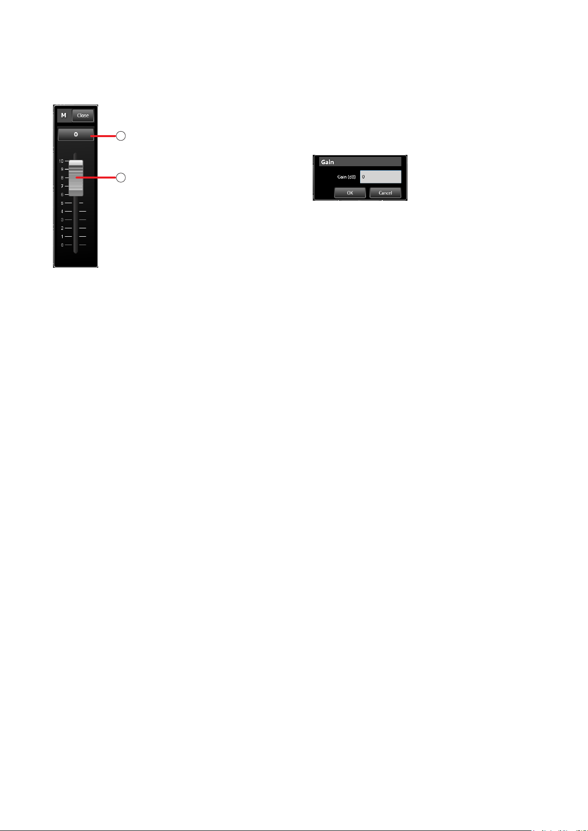
9.4. Master Volume Settings
If the Master Volume function box is clicked in the Flow View, the Detailed Setting View for the Master Volume
is displayed.
1. Gain display
Displays the Master Volume gain.
1
Gain display
Fader
2
Clicking the Gain display opens the dialog box for
gain entry.
2. Fader
Used to set the Master Volume gain. The fader
knob is displayed in the position corresponding to
the gain value. Drag the fader knob to adjust the
setting.
26
Page 27
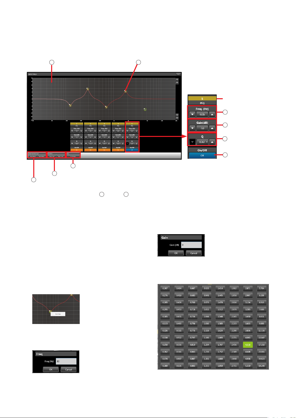
9.5. PEQ Settings
If the PEQ (parametric equalizer) function box is clicked in the Flow View, the Detailed Setting View for the PEQ
function is displayed. The frequency characteristics of each input and output can be corrected by a 5-point
parametric equalizer.
1
Filter control eld Filter point
9
Q indicator button
8
Resolution button
7
Lock button
3
The numerical values of settings
the DOWN button. Clicking the central button opens the Settings dialog box. Settings are performed by either
directly entering values or selecting given values.
through 5 above can be increased with the UP button and decreased with
2
Filter point control
Filter point
number
3
Frequency control
4
Gain control
5
Q control
On/Off button
6
1. Filter control eld
PEQ frequency characteristics are displayed by a
graph.
Each lter can be set by dragging its corresponding
lter point.
2. Filter point
Filter points are indicated by 5 yellow circles within
the lter control eld. Frequencies and gains can
be changed by dragging the lter points.
The setting value of each point can be initialized by
selecting the “Point Clear” from the menu displayed
when you right-click on the lter point on a graph.
3. Frequency control
Sets each lter point’s frequency.
[Frequency Settings dialog box]
4. Gain control
Sets each lter point’s gain.
[Gain Setting dialog box]
5. Q control
Sets each lter point’s Q.
[Frequency Setting dialog box]
27
Page 28
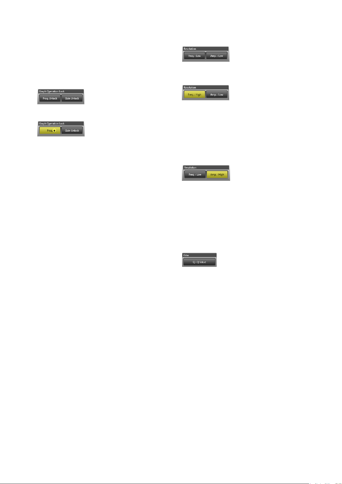
6. On/Off button
Sets each lter point to On or Off.
On: Filter is enabled (orange display).
Off: Filter is disabled (blue display).
The lter is bypassed if set to Off.
8. Resolution button
Used to set the resolution for frequency and gain
settings.
7. Lock button
Used to enable or disable the locking of frequencies
or gains when dragging lter points.
Clicking “Freq. Unlock” at left changes the
indication, locking the frequency.
If the frequency is locked, it becomes unchangeable
even if the lter point is dragged left and right.
Clicking the same button again restores the
previous display and releases the lock. Clicking
“Gain Unlock” at right changes the indication,
locking the gain.
If the gain is locked, it becomes unchangeable
even if the lter point is dragged up and down.
Clicking the same button again restores the
previous display and releases the lock.
Both the frequency and gain can be locked.
Note
Frequencies and gains can only be locked for
the lter point operation. The frequency and gain
controls can be used to change settings even while
in locked mode.
If “Freq. : Low” at left is clicked, the indication
changes and the frequency settings resolution is
set to “High.”
Clicking the same button again restores the
previous display and sets the frequency settings
resolution to “Low.” The frequency settings
resolution is as follows:
Low: 1/24 octave
High: 3-digit signicant gure
If “Gain: Low” at right is clicked, the indication
changes and the gain settings resolution is set to
“High.”
Clicking the same button again restores the
previous display and sets the for gain settings
resolution to “Low.” The gain settings resolution is
as follows:
Low: 0.5 dB
High: 0.1 dB
9. Q indicator button
Used to switch the Q display method of each lter
point.
The following 3 different display methods are
available:
(1) Numerical indication
Q values are indicated by a numerical gure.
(2) Oct/band fractional indication
The value of the octave bandwidth
corresponding to the Q value is indicated by a
fractional gure.
(3) Oct/band numerical indication
The value of the octave bandwidth
corresponding to the Q value is indicated by a
numerical gure.
Example: When the Q value is 4.318
Numerical indication: 0.333
Oct/band fractional indication:
1/3 oct/band
Oct/band numerical indication:
4.318 oct/band
28
Page 29
10. PRESET MEMORY-RELATED SETTINGS AND OPERATIONS
10.1. What Is the Preset Memory?
Parameters set in the Flow View can be stored as preset memory.
The following setting values are stored in the preset memory:
• PEQ gain, center frequency, Q and On/Off.
• Compression threshold, compression ratio, attack time, release time, gain and On/Off.
• Mute mode, On/Off for inputs 1 – 4, attenuation, hold time and fade-in time.
• Master volume.
Up to 16 preset memories can be stored.
The initial preset memory number that is called up when the power is switched on can also be set.
It is also possible to call up a different preset memory number and use parameters set in advance corresponding
to expected usage when the unit is connected to a PC online.
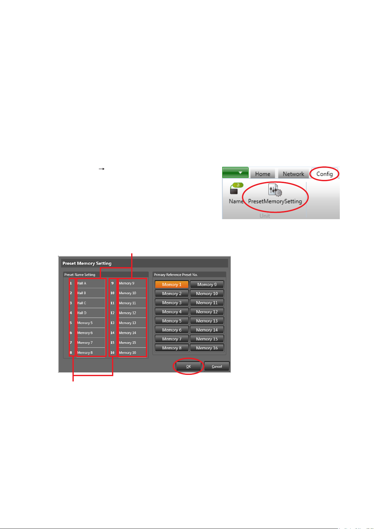
10.2. Preset Memory Name Settings
Step 1. Select [Cong Preset Memory Settings] in the Menu
View.
The Preset Memory Settings screen is displayed.
Preset memory name
2
Preset memory number
Step 2. Click the preset memory name eld and enter a name of up to 20 characters.
3
Step 3. Click the [OK] button.
29
Page 30
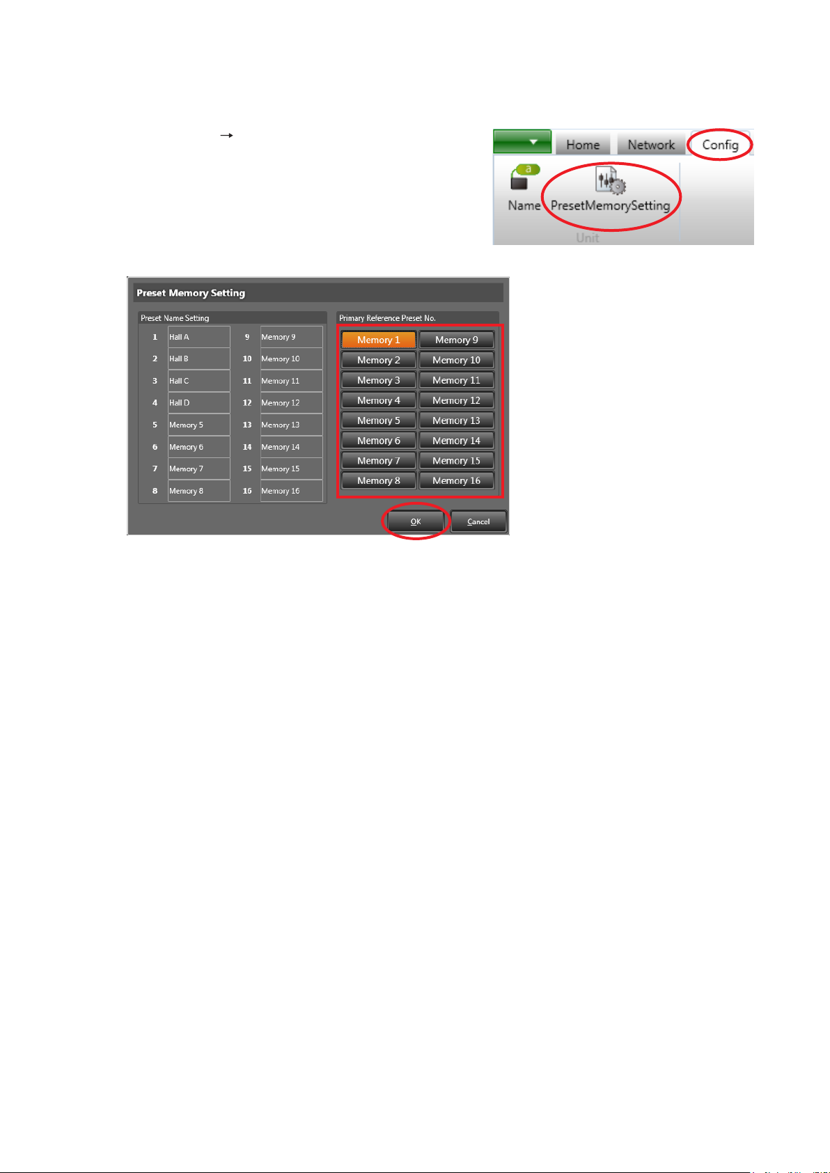
10.3. Setting the Preset Memory Number To Be Called Up When Power Is Switched On
Set the preset memory number that will be called up when the unit’s power is switched on.
Step 1. Select [Cong Preset Memory Setting] in the Menu
View.
The Preset Memory Setting screen is displayed.
2
3
Step 2. Click the button for the desired preset memory number to be called up when the power is switched on.
The clicked button lights orange.
Step 3. Click the [OK] button.
30
Page 31
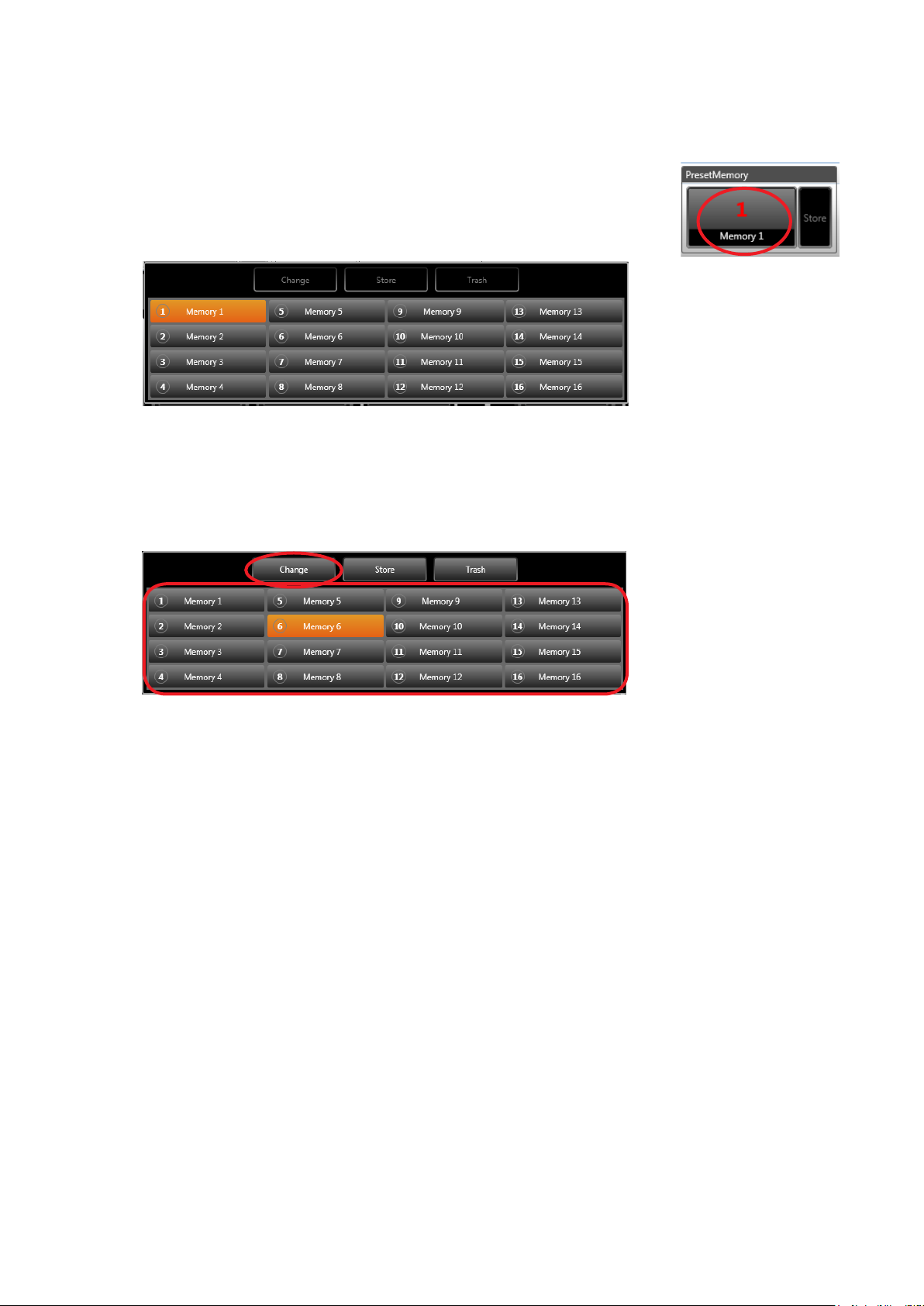
10.4. Changing the Preset Memory Number To Be Called Up
By changing the selection of the preset memory number, a setting parameter stored under the newly selected
number can be called up.
Step 1. Click the preset memory number/name button in the Memory View.
Memory List panel is displayed.
1
[Memory List panel]
The currently selected Preset Memory button is displayed in orange.
Step 2. Click the desired preset memory number/name button on the Memory List panel.
The selected button lights orange.
3
Step 3. Click the [Change] button.
The setting parameters for the preset memory number selected in Step 2 are called up.
2
31
Page 32
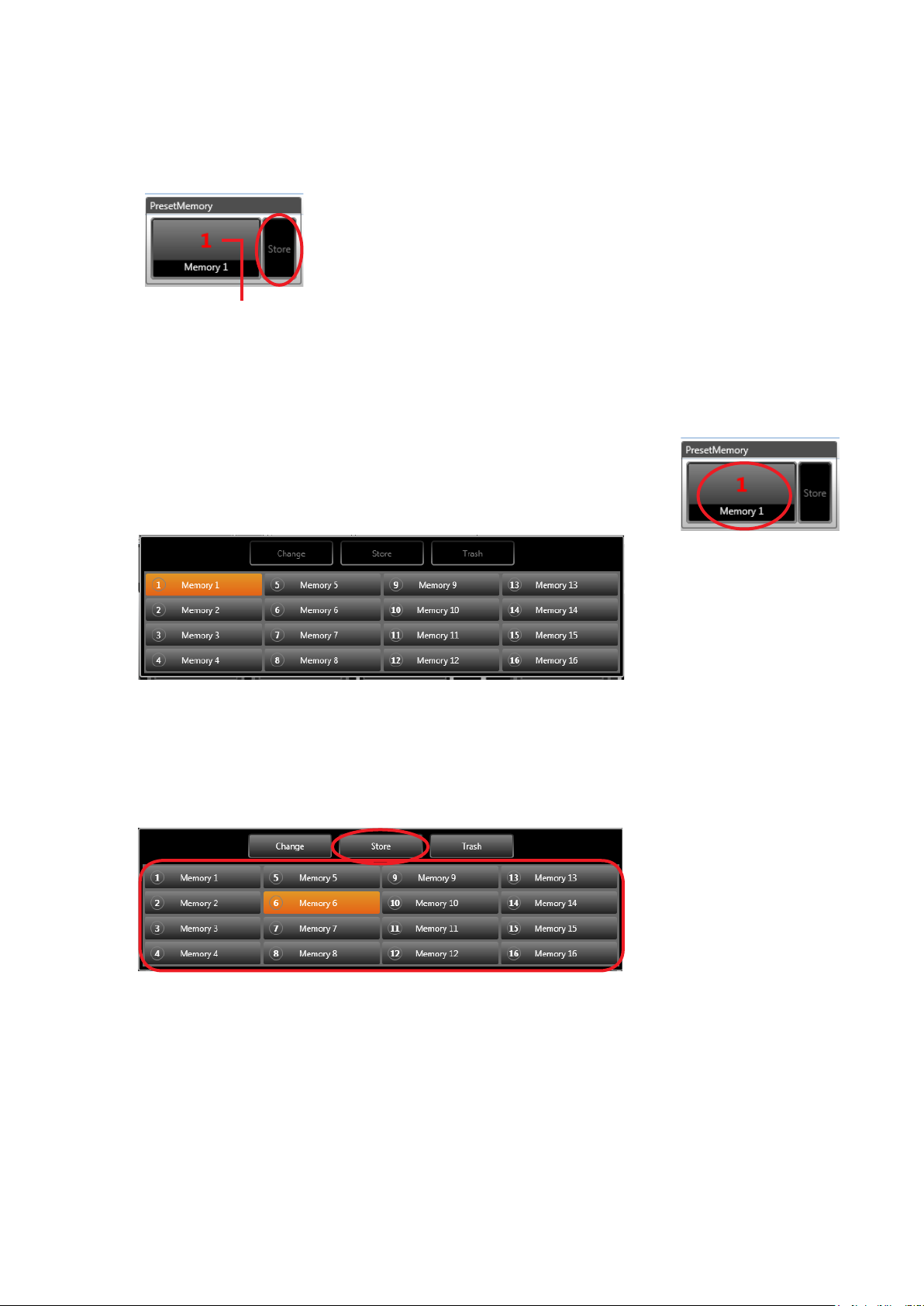
10.5. Storing Set Parameters in Preset Memory
10.5.1. When storing in a currently-selected preset memory number:
Step: Click the [Store] button in the Memory View.
Parameters set in the Flow View are stored in the current preset memory number.
Stored in the preset memory number shown here.
10.5.2. When storing parameters in a different preset memory number:
Step 1. Click the preset memory number/name button in the Memory View.
Memory List panel is displayed.
[Memory List panel]
The currently selected Preset Memory button is displayed in orange.
Step 2. Click the desired preset memory number/name button in the Memory List panel.
The selected button lights orange.
3
2
1
Step 3. Click the [Store] button.
Parameters set in the Flow View are stored in the memory number selected in Step 2.
32
Page 33
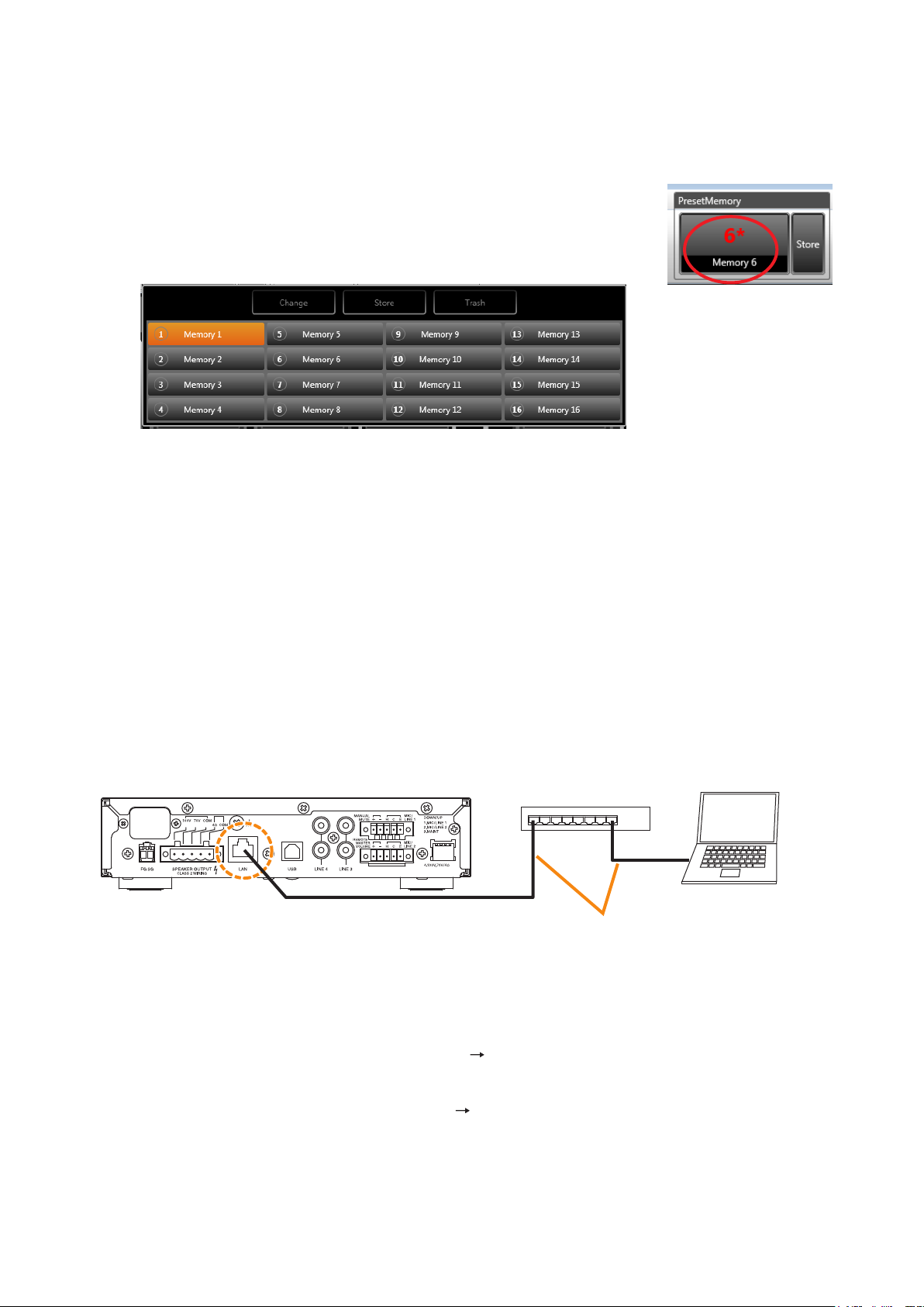
10.5.3. Deleting Edited Contents Without Storing Them in Preset Memory
When wishing to return the parameters edited in the Flow View back to those currently stored, delete the edit.
Note: Once the edit contents have been deleted, they cannot be restored.
Step 1. Click the preset memory number/name button in the Memory View.
Memory List panel is displayed.
[Memory List panel]
The currently selected Preset Memory button is displayed in orange.
Step 2. Click the [Trash] button.
After the edited contents are deleted, the parameters stored before the edit are called up.
1
11. COMMUNICATION SETTINGS
11.1. Connections between the PC and the Unit
Connect the unit’s LAN terminal to the PC via a switching hub.
Connect a PC and the unit to a switching hub using LAN straight-through cables individually.
PC with the A-5000 PC
Software installed
A-5006/5012
LAN terminal
Switching hub
Category 5 or higher shielded twisted
pair straight-through cable for LAN
(with RJ45 connectors)
11.2. Method to Enable Communications between the PC and the Unit
Step 1. Perform network settings by selecting [Network Connection Settings] from the menu view.
(See the next page “Connection Settings.”)
Step 2. Make Communications by selecting [Network Connect] from the menu view.
(See p. 37 “11.4. Communications.”)
33
Page 34
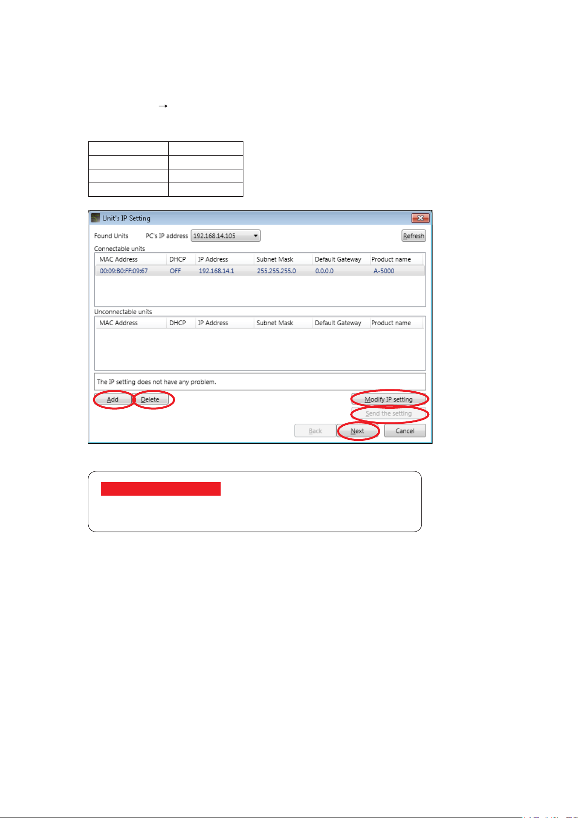
11.3. Connection Settings
Perform settings needed to communicate with the units in this section.
Network settings can be made.
Step 1. Select [Network Connection Setting] from the menu.
Network settings of the units found on the network are displayed.
The table below shows the factory preset settings for each unit.
IP address 192.16 8 .14.1
Subnet mask 255.255.255.0
Default gateway 0.0.0.0
DHCP Off
2
4 5
3
6
If no unit was detected:
Install the undetected unit within the reach of broadcast packet.
Communications may be interrupted when the PC is rewall-protected.
If a unit’s IP address is duplicated or inappropriate network setting has been performed, such device is displayed
in the Unconnectable units list.
• To change the unit’s IP address setting, advance to Step 2.
• When transmitting the settings data changed in Step 2 to the unit, advance to Step 3.
• When changing the PC’s network settings, change them from the Windows Control Panel. PC network setting
cannot be changed using the A-5000 PC software.
• When connecting to the unit via a router, network settings are not displayed on this screen. The unit network
settings cannot be changed. Connect such unit to a LAN and perform the network settings in advance.
• If a unit needs to be connected via a router, advance to Step 4 to add it.
• If the unit that should not be communicated with is displayed in the list, advance to Step 5 to delete it from the
list.
• Advance to Step 6 when all the units to be connected are displayed in “Connectable units” list.
• When the PC has two or more IP addresses, select the unit and IP address to be communicated with from
the PC’s IP address.
• When the DHCP is set to be valid and the DHCP server is not found on the network, equipment detection
cannot be performed until communications between the DHCP server and PC time out (approximately 30
seconds).
Note that the DHCP is set to be invalid by default (see Step 2 of the next page).
34
Page 35
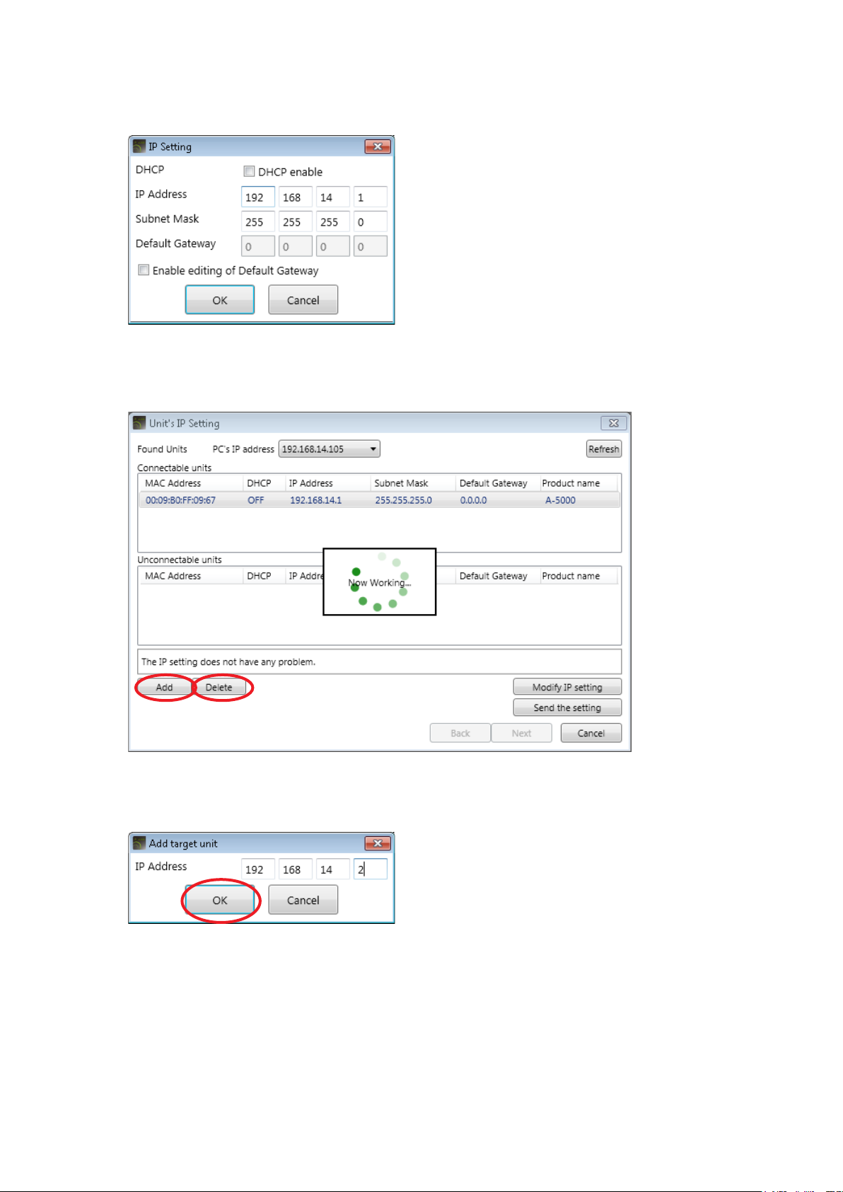
Step 2. Change the unit’s network setting.
Select the unit for which you want to change the network setting, then click the [Modify IP setting]
button. The IP Setting screen is displayed.
Set the IP address, then click the [OK] button.
Step 3. Transmit changed setting data to the unit.
Clicking the [Send the setting] button transmits the IP settings to the corresponding unit and network
setting for the unit is changed.
4 5
Step 4. Add the unit to be connected via a router in a list. Clicking the [Add] button displays the Add target unit
screen. Enter the IP address of the added unit and click the [OK] button.
4
Note
Network setting for the unit to be connected via a router cannot be changed using the method described
in Step 2.
If you need to change the network setting, connect such unit to a LAN and change the network setting
in advance.
35
Page 36
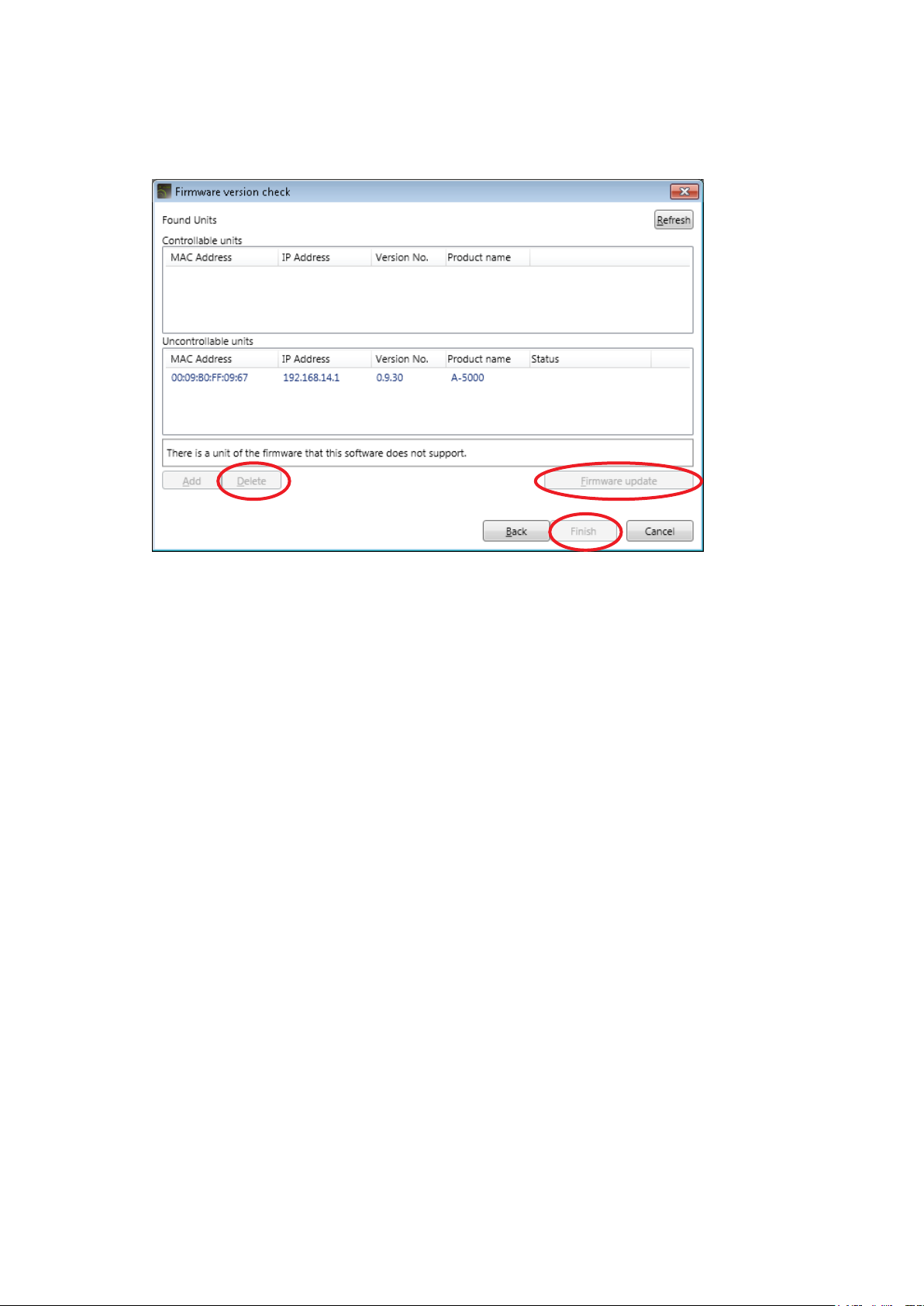
Step 5. Delete the unit from the list.
Select the unit to be deleted, then click the [Delete] button.
The selected unit is deleted from the list.
Step 6. Click the [Next] button, then the Firmware version check screen is displayed.
8
7
When the rmware version of the unit is older than that the A-5000 PC software supports, the unit is
displayed in the Uncontrollable units list.
• If a unit that does not need to be controlled is displayed, advance to Step 7 to delete it from the list.
• When updating rmware, advance to Step 8 .
• If all units to be controlled are shown in the Controllable units list, advance to Step 9.
Step 7. Delete the unit from the list.
Select the unit to be deleted, then click the [Delete] button.
The selected unit is deleted from the list.
Step 8. Update the rmware.
Select the unit from the Uncontrollable units list and click the [Firmware update] button.
Firmware update starts.
The unit is moved to and displayed in the Controllable units list after the rmware update is complete.
Notes
• Do not switch off the unit’s power under any circumstances during rmware update.
• Settings data is retained even if the rmware is updated.
• Firmware cannot be updated if the unit’s maintenance switch (DIP Switch 3) is in the UP position.
Be sure that the maintenance switch is in the DOWN position and restart the unit before updating.
10
Step 9. Select the unit(s) from the Controllable units list.
Step 10. Click the [Finish] button.
Setting is complete.
36
Page 37
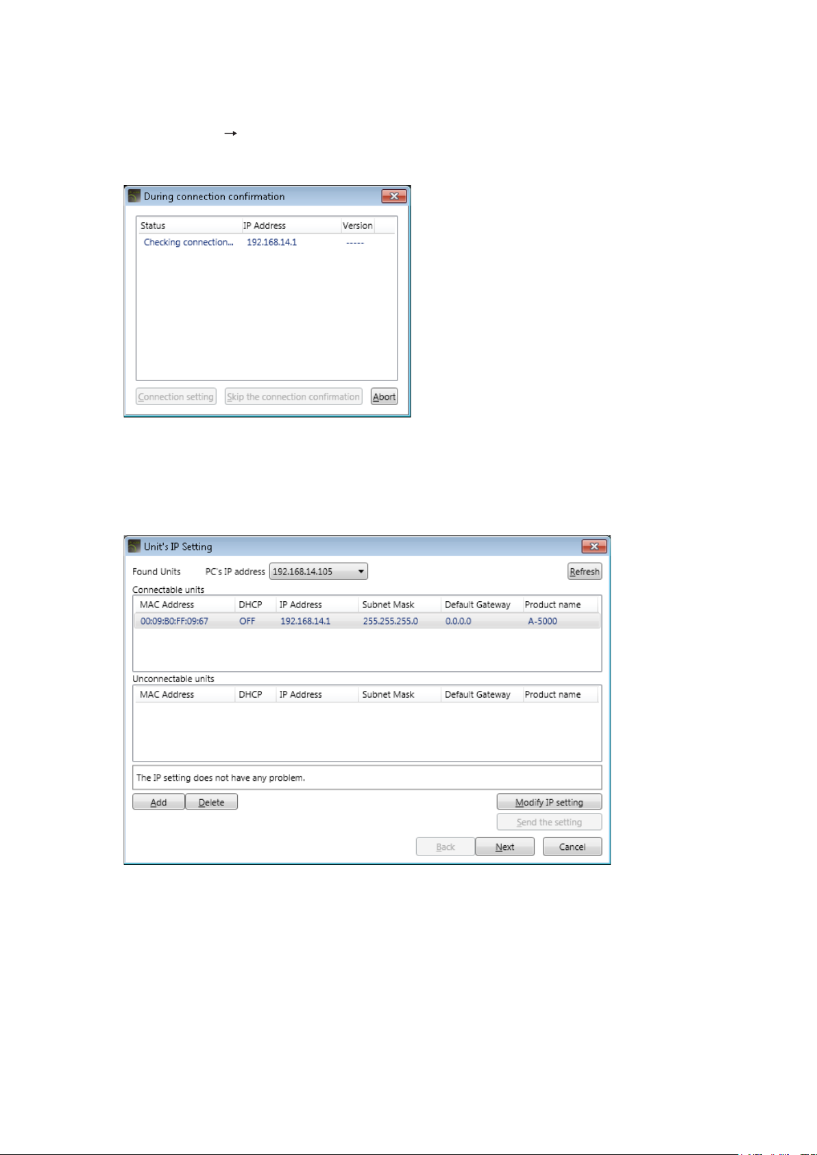
11.4. Communications
Connect to the unit displayed “Connectable units” eld in the Unit’s IP setting screen.
Step 1. Select [Network Connect] from the menu.
While the screen below is displayed, the target unit designated with the connection settings are being
detected.
Note
If no units on the network have been set for the connection settings, the Unit’s IP Setting screen is
displayed.
Perform network settings in the same manner as in the steps on p. 34, “Connection Settings.”
On completion of network settings, the units listed in “Connectable units” eld start being connected.
37
Page 38
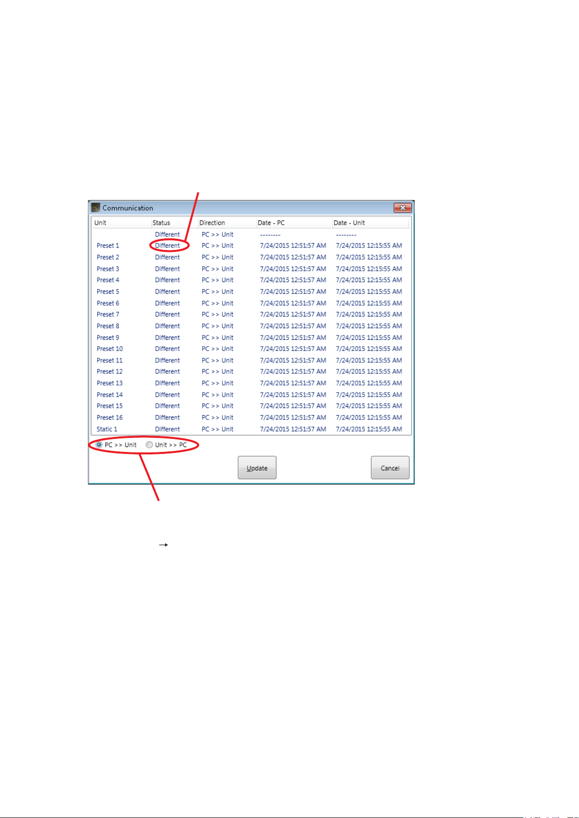
Step 2. Match both setting data of the PC and the unit if not identical.
To enable communications between the PC and the unit, both setting data* must be the same.
If data is different between the PC and the target unit, the Communication screen appears indicating
“Different” in the Status column during connection.
Designate the transfer direction “PC >> Unit” or “Unit >> PC,” and click the [Update] button. Then, all
unmatched setting data is simultaneously transferred in the designated direction.
* Set contents of preset memory Nos. 1 – 16 and parameters (static parameter) not stored in preset
memory.
[Example of display that appears when the settings contents for the PC and the unit do not match]
Preset Memory 1 settings do not match.
Step 3. Select [Network
This terminates communications between a PC and the unit.
Select the transfer method.
Disconnect] from the menu.
38
Page 39

12. GLOSSARY
12.1. PC Software Screen
12.1.1. Flow view
Displays the A-5000 series’s signal processing ow, and is used to perform advanced settings of each individual
signal processing function.
12.1.2. Box
Refers to the box expressing each signal processing function in the Flow view and Operation view. The Box is
also termed as Function box.
12.1.3. Detail setting panel
A screen used to perform detailed parameter settings for the signal processing function box.
12.2. Signal Processing Function
12.2.1. Compressor function
Compresses the difference between the maximum sound output and minimum sound output. This function can
be set for Inputs 1 and 2.
Threshold Level, Compression Ratio, Attack Time, Release Time and Gain can all be individually adjusted.
12.2.2. Manual mute function
Input signal is muted by closing the unit’s Manual Mute terminals.
Mute can be individually set for each input (1 – 4).
12.2.3. Volume function
The following volume control functions are also provided:
• Input Volume Controls
Each of these front panel-mounted controls can be rotated to adjust its corresponding signal level.
• Remote Master Volume Controls
• Master Volume Controls
12.2.4. PEQ function
Performs 5-point PEQ lter processing on input and output channels.
39
Page 40

12.3. System Function
12.3.1. Preset
Refers to the Preset memory.
12.3.2. Static
A parameter that cannot be stored in the Preset memory.
12.3.3. During editing (Edit state)
A state that even a part of the parameters to be stored in the Preset memory is currently being changed.
12.3.4. Preset resume function
A function that resumes the editing after power-on even if power is turned off while editing is in progress not
completing the store into a specic Preset memory.
12.4. Communication Related Terms
12.4.1. Online state
A state that the PC and target A-5000 series unit are communicating with each other.
“When in online mode” is a state that the A-5000 series unit is in online state.
12.4.2. Offline state
A state that the PC and target A-5000 series unit are not communicating with each other.
“When in ofine mode” is a state that the A-5000 series unit is in ofine state.
12.5. External Control Functions
12.5.1. Manual mute function
Input signal is muted by closing the unit’s Manual Mute terminals.
12.5.2. Remote master volume control function
Adjusts the unit’s master volume with an external volume control.
12.6. Maintenance Function
12.6.1. Setting file
A le in which the setting data for a single A-5000 series unit is stored.
The le extension is “a5d.”
40
Page 41
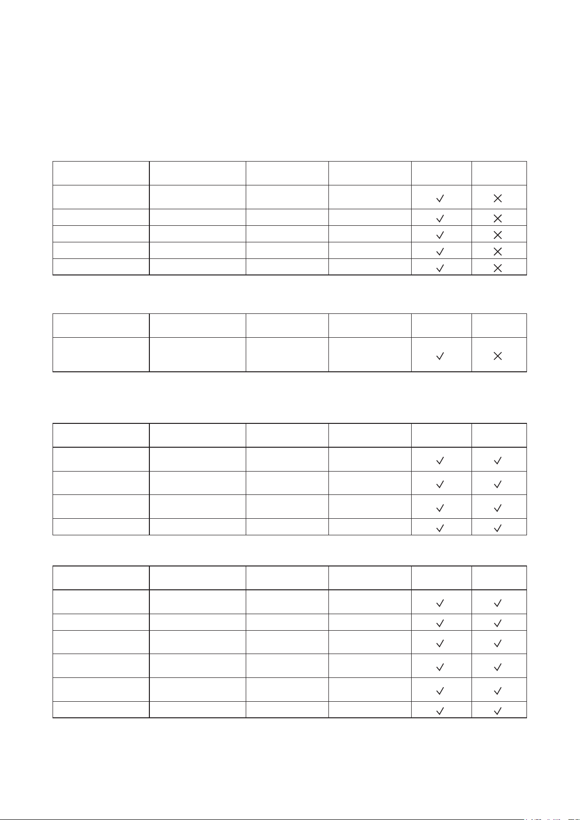
13. SPECIFICATIONS
13.1. Software Specification
Preset Memory: 16 memories
13.2. Setting/Display Items, Setting Ranges, and Default Settings
13.2.1. Unit data
Setting Item Setting Range Default Setting Remarks Online Setting
Unit Name
IP Address IPv4 192.16 8 .14.1
Subnet Mask IPv4 255.255.255.0
Default Gateway IPv4 0.0.0.0
DHCP On, Off Off
20 alphanumeric
characters
13.2.2. Channel data
Setting Item Setting Range Default Setting Remarks Online Setting
Example:
Mono In: 1, Mono
Out: 1
Channel Name
20 alphanumeric
characters
13.2.3. Signal processing box
[PEQ]
Setting Item Setting Range Default Setting Remarks Online Setting
Gain
Center Frequency
Q
On/Off On, Off On
–15 to +15 (dB),
0.5 dB steps
20 to 20 k (Hz),
1/24 octave steps
0.267 to 69.249
(96 points)
0
80, 200, 500, 2 k,
10 k
4.318
PEQ
Storable in
Preset Memory
Storable in
Preset Memory
Storable in
Preset Memory
[Compressor]
Setting Item Setting Range Default Setting Remarks Online Setting
Threshold
Ratio 1 : 1 to ∞ : 1, 17 steps 1 : 1
Attack time
Release time
Gain
On/Off On, Off On
–30 to +10 (dB), 1 dB
steps
0.2 to 5000 (ms),
25 steps
10 to 5000 (ms),
16 steps
–20 to +10 (dB),
1 dB steps
0
10
500
0
Storable in
Preset Memory
41
Page 42
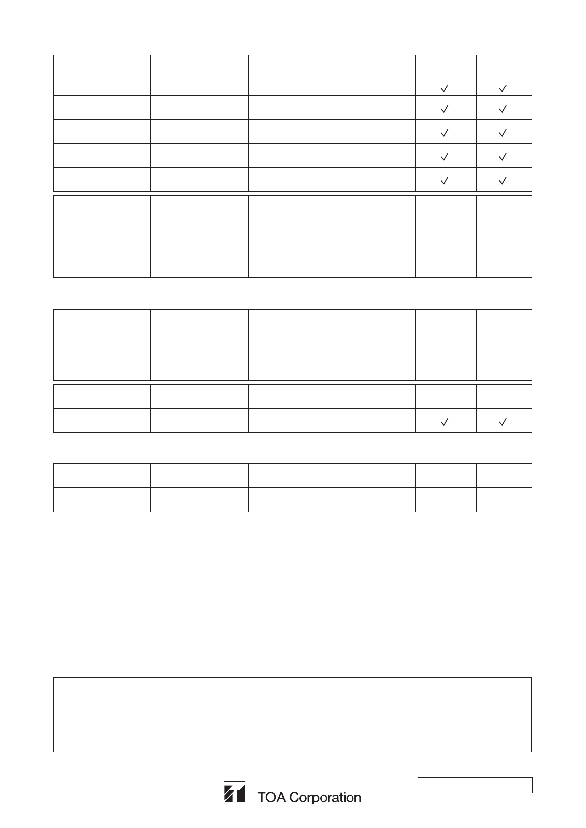
[Mute]
Setting Item Setting Range Default Setting Remarks Online Setting
Mute mode Manual, Off Manual
INPUT 1 – 4
On/Off
Attenuation
Hold Time
Fade-in Time
On, Off Off
–60 to –3 (dB),
1 dB steps
1 to 10 (sec),
1 sec steps
0 to 10 (sec),
1 sec steps
–40
5
4
Storable in
Preset Memory
Display Item Setting Range Default Setting Remarks Online Setting
Mute operation status
Manual Mute terminal
status
Mute enabled/
disabled
Open/close –
– – –
Unit’s Manual
Mute terminal
status
[Volume control]
Display Item Setting Range Default Setting Remarks Online Setting
Input volume control
Remote master
volume control
Setting Item Setting Range Default Setting Remarks Online Setting
Master volume control
–∞, –69 to +10 (dB),
1 dB steps
–∞, –69 to +10 (dB),
1 dB steps
–∞, –69 to +10 (dB),
1 dB steps
– – –
– – –
0
[Output selection switch]
Display Item Setting Range Default Setting Remarks Online Setting
Output 100 V, 70 V/4 ohm –
Use the unit’s DIP
switch to set.
Storable in
Preset Memory
– –
Storable in
Preset Memory
Storable in
Preset Memory
Storable in
Preset Memory
– –
Traceability Information for Europe
Manufacturer:
TOA Corporation
7-2-1, Minatojima-Nakamachi, Chuo-ku, Kobe, Hyogo,
Japan
Authorized representative:
TOA Electronics Europe GmbH
Suederstrasse 282, 20537 Hamburg,
Germany
URL: http://www.toa.jp/
161-10-00009-00
 Loading...