

Page 1
OPERATING INSTRUCTIONS
PA AMPLIFIER A-230 HV
Please follow the instructions in this manual to obtain the optimum results from this unit.
We also recommend that you keep this manual handy for future reference.
1. SAFETY PRECAUTIONS ........................... 2
2. GENERAL DESCRIPTION ......................... 3
3. FEATURES ................................................. 3
4. NOMENCLATURE AND FUNCTIONS
4.1. Front ..................................................... 3
4.2. Rear ...................................................... 4
5. MUTING FUNCTION ................................... 4
6. INSTALLATION .......................................... 5
7. CONNECTIONS
7.1. Input Connections ................................ 5
7.2. Output Connections .............................. 5
7.3.
Example of External Equipment Connections
.... 6
8. VOLUME CONTROL SETTINGS ............... 6
9. BLOCK & LEVEL DIAGRAM ..................... 7
10. DIMENSIONAL DIAGRAM ......................... 7
11. SPECIFICATIONS ...................................... 8
TABLE OF CONTENTS
Page 2
2
When Installing the Unit
• Do not expose the unit to rain or an environment
where it may be splashed by water or other liquids,
as doing so may result in fire or electric shock.
• Use the unit only with the voltage specified on the
unit. Using a voltage higher than that which is
specified may result in fire or electric shock.
• Do not cut, kink, otherwise damage nor modify the
power supply cord. In addition, avoid using the
power cord in close proximity to heaters, and never
place heavy objects -- including the unit itself -- on
the power cord, as doing so may result in fire or
electric shock.
• The terminals marked with the symbol are
hazardous live. The external wiring to these
terminals requires installation by an instructed
person.
• The socket-outlet shall be installed near the
equipment and the plug (disconnecting device)
shall be easily accessible.
• Be sure to replace the unit's terminal cover after
connection completion. Because the voltage of up
to 100 V is applied to the high impedance speaker
terminals, never touch these terminals to avoid
electric shock.
• Be sure to ground to the safety ground (earth)
terminal to avoid electric shock. Never ground to a
gas pipe as a catastrophic disaster may result.
When the Unit is in Use
• Should the following irregularity be found during
use, immediately switch off the power, disconnect
the power supply plug from the AC outlet and
contact your nearest TOA dealer. Make no further
attempt to operate the unit in this condition as this
may cause fire or electric shock.
· If you detect smoke or a strange smell coming
from the unit.
· If water or any metallic object gets into the unit
· If the unit falls, or the unit case breaks
· If the power supply cord is damaged (exposure of
the core, disconnection, etc.)
· If it is malfunctioning (no tone sounds.)
• To prevent a fire or electric shock, never open nor
remove the unit case as there are high voltage
components inside the unit. Refer all servicing to
you nearest TOA dealer.
• Do not place cups, bowls, or other containers of
liquid or metallic objects on top of the unit. If they
accidentally spill into the unit, this may cause a fire
or electric shock.
• Do not insert nor drop metallic object or flammable
materials in the ventilation slots of the unit's cover,
as this may result in fire or electric shock.
When Installing the Unit
• Never plug in nor remove the power supply plug
with wet hands, as doing so may cause electric
shock.
• When unplugging the power supply cord, be sure
to grasp the power supply plug; never pull on the
cord itself. Operating the unit with a damaged
power supply cord may cause a fire or electric
shock.
1. SAFETY PRECAUTIONS
• Be sure to read the instructions in this section carefully before use.
• Make sure to observe the instructions in this manual as the conventions of safety symbols and messages
regarded as very important precautions are included.
• We also recommend you keep this instruction manual handy for future reference.
Safety Symbol and Message Conventions
Safety symbols and messages described below are used in this manual to prevent bodily injury and property
damage which could result from mishandling.
Before operating your product, read this manual first and understand the safety symbols and messages so
you are thoroughly aware of the potential safety hazards.
WARNING
Indicates a potentially hazardous situation which, if mishandled, could
result in death or serious personal injury.
Indicates a potentially hazardous situation which, if mishandled, could
result in moderate or minor personal injury, and/or property damage.
WARNING
CAUTION
CAUTION
Page 3
3
• When moving the unit, be sure to remove its power
supply cord from the wall outlet. Moving the unit
with the power cord connected to the outlet may
cause damage to the power cord, resulting in fire or
electric shock. When removing the power cord, be
sure to hold its plug to pull.
• Do not block the upper panel ventilation slots in the
unit's cover. Doing so may cause heat to build up
inside the unit and result in fire.
• Avoid installing the unit in humid or dusty locations,
in locations exposed to the direct sunlight, near the
heaters, or in locations generating sooty smoke or
steam as doing otherwise may result in fire or
electric shock.
When the Unit is in Use
• Do not place heavy objects on the unit as this may
cause it to fall or break which may result in
personal injury and/or property damage. In
addition, the object itself may fall off and cause
injury and/or damage.
2. GENERAL DESCRIPTION
TOA's Basic Amplifier A-230 is a high cost-performance mixer power amplifier suited for paging
announcement or background music in schools, offices, shops, factories, mosques, churches, and small
rooms.
3. FEATURES
• High durability, high reliability, and high performance.
• Three microphone inputs and one AUX input.
• Speaker output of constant voltage distribution system (100 V) and low impedance (4 Ω).
• Operates on AC or DC power.
• Muting function.
• Independent input volume controls.
• Independent tone controls of cut type for both high and low frequencies.
• Current limiter circuitry protects transistors against a failure due to overheat.
4. NOMENCLATURE AND FUNCTIONS
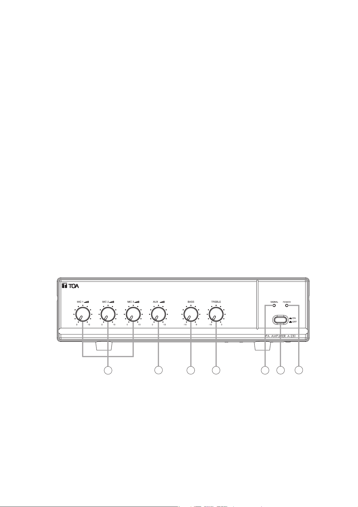
4.1. Front
1. Power switch
Press to turn on the power.
Press again to turn off the power.
2. Power Indicator
Lights green when power is switched ON.
3. Microphone Volume Controls
Adjust the microphone level.
4. AUX Volume Control
Adjusts the AUX level.
5. Bass Control
Adjusts bass response. Rotate counterclockwise
to reduce it. The maximum position "0" provides
flat characteristics.
6. Treble Control
Adjusts treble response. Rotate counterclockwise
to reduce it. The maximum position "0" provides
flat characteristics.
7. Signal Indicator
Lights green when power is switched ON, and
indicates an output signal level.
3
4
5
6
1
7
2
Page 4

4
4.2. Rear
8. AC Power Cord
Connects to an AC power source.
9. DC Terminals
Connect to a DC power supply of 12V.
10. Output Terminals
Connect to speakers. When connecting
speakers, use only one of the speaker output
terminals, low or high impedance.
11. Terminal Cover
To avoid electric shock due to high voltage from
output terminals, replace the terminal cover after
connection completion.
12. AUX Input Terminals
–20 dBV (100 mV), 10 kΩ, unbalanced,
monaural RCA pin jacks. Accept external
equipment output signals. (Refer to Input
Connection for details.)
13. MIC 1, MIC 2 and MIC 3 Inputs
–60 dBV (1 mV), 600 Ω, unbalanced.
Because microphone input is unbalanced type,
use a single pole phone plug. (Refer to Input
Connection for details.)
14. Muting Level Control
Adjusts the background music level 0 – 30 dB to
be automatically reduced when priority function
is operated.
15. Ground Terminal
Connects to ground (earth) to avoid electric
shock.
0 dBV=1 V
5. MUTING FUNCTION
Mic 1 input is provided with a voice-activated muting function that overrides other Mic inputs 2 and 3, and AUX
input. (Factory default: –30 dB)
Remark: About Mute function.
• When the audio signal is input to Mic1, the mute circuit works promptly.
• When the signal disappears, it returns to the previous state after 3 seconds.
8
9
10
11
12
13
14 15
MUTE ADJ
0
–30dB
Page 5

5
7. CONNECTIONS
7.1. Input Connections
•
Mic 1, Mic 2, Mic 3 Connection (Phone Plug)
•
AUX input Connections (RCA pin jack)
6. INSTALLATION
Keep the unit over 10 cm away from objects that may obstruct air flow to prevent the unit's internal
temperature rise.
7.2. Output Connections
Be sure to replace the supplied terminal cover after connection
completion. Because high voltage is applied to the speaker terminals,
never touch these terminals to avoid electric shock.
CAUTION
•
Low Impedance Speaker
•
100 V Line Speaker
CAUTION!
• The 4 Ω and 100 V terminals cannot be used at the same time.
• Impedance indicated above the terminal represents the total speaker
(load) impedance.
Total impedance of 100 V line is 330 Ω.
over 10 cm
over 10 cm over 10 cm
Single Pole Phone Plug
COM– +12 V 4Ω 100V
MIC
Single core shielded cable
Single core shielded cable
Signal source
(Tuner,
Cassette Tape, etc)
COM–+12 V 4Ω100V
To Mic input
4 − 8Ω
Speaker
100 V Line
Speaker
Page 6

6
7.3. Example of External Equipment Connections
8. VOLUME CONTROL SETTINGS
Output levels are adjustable with individual volume controls. For music play or announcement, adjust the
corresponding volume control so that the signal output is not distorted.
Note that the sound quality is downgraded when the output is distorted.
AC Mains
100 V Line
Horn Speaker with
Matching Transformer
Dynamic Microphone
Dynamic Microphone
Dynamic Microphone
12 V DC Battery
100 V Line
Column Speaker with
Matching Transformer
Radio Tuner, CD Player, or Cassette Deck Player
Page 7

7
Power LED
Signal Level LED
Tone
Bass Treble
OT
Mute Level
0 to –30 dB
Aux
–20 dBV
Pre-Amp
Output
0 dBV
Mixing
–20 dBV
Power Amp
100 V output
+40 dBV
+40
–60
–40
–20
+20
0 dBV
Mic
–60 dBV
MIC3
600 Ω, –60 dBV
Unbalanced
MIC2
600 Ω, –60 dBV
Unbalanced
MIC1
600 Ω, –60 dBV,
Unbalanced
AUX
10 kΩ, –20 dBV
Unbalanced
DC
Fuse
PT
AC
Fuse
100 V
4 Ω
COM
+12 V
–
DC Input
AC Main
50/60 Hz
9. BLOCK & LEVEL DIAGRAM
10. DIMENSIONAL DIAGRAM
0 dBV = 1 V
[Rear]
[Top]
[Side]
[Front]
11.8 88.4 11.96 205.1 23.2
350
Page 8

Model No. A-230 HV
Power Source 220 – 230 V AC or 12 V DC
Rated Output 30 W
Power Consumption
(EN60065)
34 W
DC Current Consumption
(at rated output)
4.5 A
Frequency Response 50 – 20 kHz, ±3 dB
Distortion Less than 1% at 1 kHz, 1/3 Rated Power
MIC 1 –60 dBV (1.0 mV), 600 Ω, Unbalanced, Phone jack
MIC 2 –60 dBV (1.0 mV), 600 Ω, Unbalanced, Phone jack
MIC 3 –60 dBV (1.0 mV), 600 Ω, Unbalanced, Phone jack
AUX –20 dBV (100 mV), 10 kΩ, Unbalanced, RCA pin jack
Speaker Out All Speaker Outputs are Floating Balanced
100 V 330 Ω
4 Ω 11 V
S/N Rasio
Over 60 dB (MIC1,2,3)
Over 70 dB (AUX)
Tone Controls
Bass: –10 dB at 100 Hz
Treble: –10 dB at 10 kHz
Muting
MIC1 overrides other Mic inputs and AUX input with 0 – 30 dB
attenuation by MIC 1 input signals.
Indicators Power LED, Signal LED
Finish
Panel: ABS Resin, Black
Case: Steel Plate, Black
Dimensions 350 (W) x 100 (H) x 240 (D) mm
Notes
* 0 dBV = 1 V
* Specifications are measured on 230 V AC.
* The design and specifications are subject to change without notice for improvement.
533-01-066-20
URL: http://www.toa.jp/
11. SPECIFICATIONS
Inputs
Outputs
 Loading...