

Page 1
When using the WMK-Series mounting kit on a combustible wall, it is recommended to
use vent pipe rated for reduced clearances to combustibles. Vent pipe manufacturer’s
clearances must be adhered to.
WMK mounting location must be based on “Termination Clearances” found in the
Auto-Draft instruction manual for U.S. and Canadian installations.
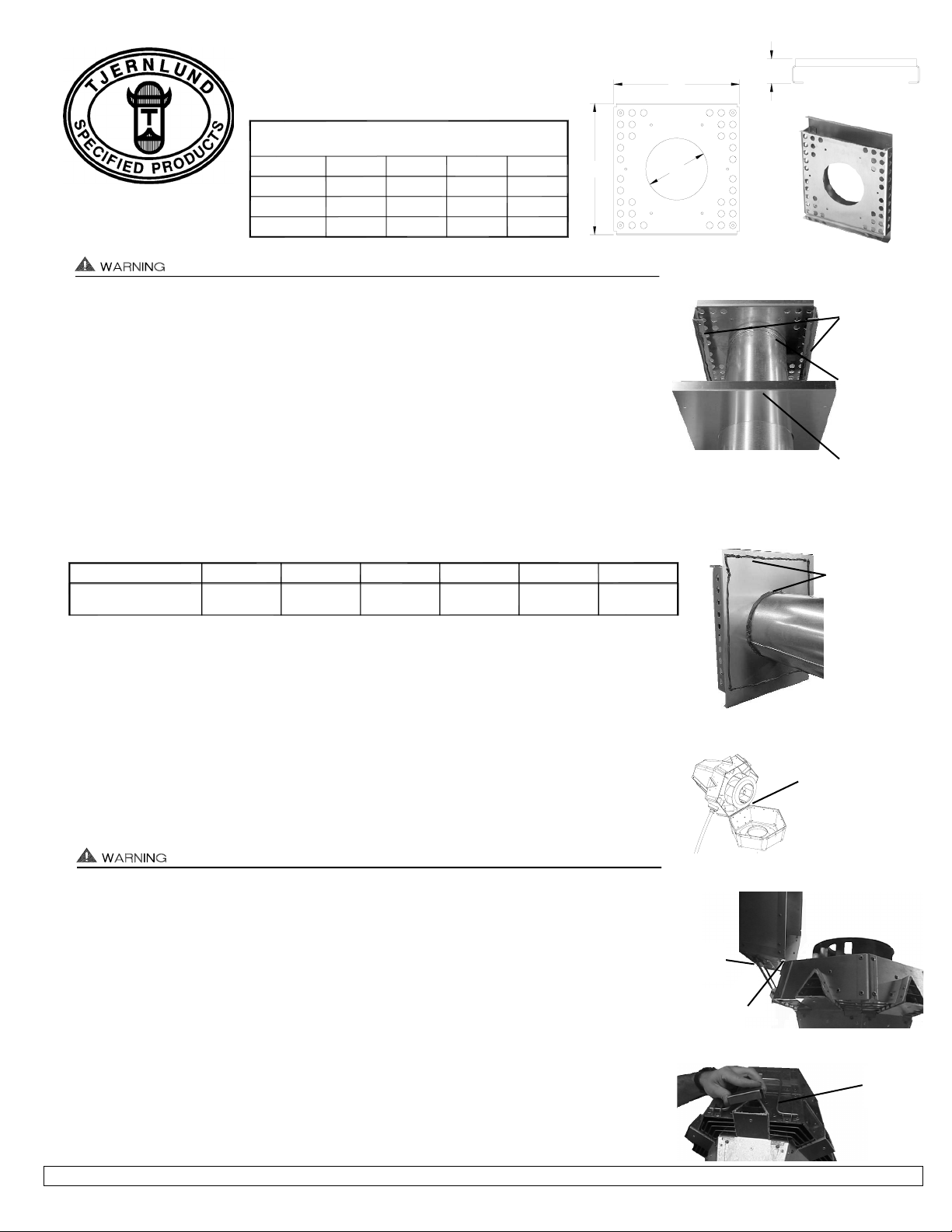
IMPORTANT: The diameter of hole in the Backing Plate for each kit is 9 1/8” for WMK-8, 11 1/8”
for WMK-10, 13 1/8” for WMK-12. The Backing Plate hole may be trimmed out for larger pipe
diameters.
1. Using Backing plate as a template, center over opening on wall to mark bolt hole locations on
wall. There are (4) for the WMK-8 and (8) for the WMK-10 & WMK-12. Flanges of Backing
Plate must face top and bottom. IMPORTANT: Flanges of backing plate must be level when
marking bolt hole locations on wall, (See Diagram A). Drill out and tap holes as necessary for
appropriate lag bolts to support the weight of the Auto-Draft® unit as shown below.
2. Insert Inlet Collar through WMK and secure the Inlet Collar with self tapping stainless steel
screws to a length of vent pipe required to get through wall. Make sure the screws are long
enough to penetrate vent pipe to adequately secure Inlet Collar. Slide Backing Plate
over vent pipe with flanges facing towards WMK. Place a bead of hi-temp silicone on WMK
back flange and slide Backing Plate up to WMK, (See Diagram A).
3. With Backing Plate pushed against WMK hi-temp siliconed flange, place a bead of hi-temp
silicone on the Backing Plate back side around perimeter of pipe opening and perimeter of
Backing Plate and firmly push assembly against wall with flanges facing top and bottom, (See
Diagram B). WMK and Backing Plate must be level. Secure WMK and Backing Plate to wall
with appropriate stainless steel lag bolts, washers and lock nuts, installer supplied. Hardware
utilized must support Auto-Draft® weight as shown above.
Auto-Draft® motor side is heavy. Housing hinge pin should be removed for easier installation. Support Venter base when removing hinge pin. When removing motor side, use
extreme caution so internal parts such as the impeller are not damaged, (See Diagram C).
4. IMPORTANT: Housing hinge must face down when mounting on a side wall, (See Diagram D).
Align WMK studs with holes in Auto-Draft® Inducer base, insert stainless steel washers
and secure the Auto-Draft® to the WMK with provided stainless steel keps nuts.
5. Seal around the Inducer base and the WMK with hi-temp silicone. Make sure it is watertight
so water can’t slip in between the Inducer base and WMK.
6. Reattach Auto-Draft® motor side to Base making sure that hinge pin is fully inserted in
hinges, (See Diagram C).
7. Apply a bead of hi-temp silicone on the cooling air inlet on top of Auto-Draft® and firmly
adhere triangle shaped cooling air inlet cover to cooling air inlet, (See Diagram E). This
procedure will prevent rain and/or snow from entering Inducer.
DIAGRAM E
TOP
COOLING
AIR INLET
DIAGRAM D
HOUSING
HINGE MUST
POINT DOWN.
SUPPORT
HANDLE
BRACKET
DIAGRAM C
HINGE PIN & MOTOR
SIDE SHOULD BE
REMOVED FOR
EASIER INSTALLATION.
SUPPORT VENTER
BASE AND MOTOR SIDE
WHEN REMOVING PIN.
DIAGRAM B
Centrifugal Impeller
FSAD-8 FSAD-10 FSAD-12 VSAD-8 VSAD-10 VSAD-12
MODEL
Fan Type
47
21.32
97
43.99
138
62.59
48
21.77
101
45.80
140
63.49
kgs
lbsWeight
WMK SERIES WALL MOUNT KIT DIMENSIONS
WMK-8
WMK-10
WMK-12 29.00
24.00
17.00
28.38
23.25
16.25
3.25
3.38
3.25
12.00
10.00
8.00
DCBA
(ALL DIMENSIONS ARE IN INCHES)
DA
B
FIGURE WMK 1b
C
WMK SERIES WALL MOUNTING KITS
Constructed out of rugged 5052 Aluminum.
ETL Recognized for zero - clearance
termination on combustible walls.
Tjernlund Products, Inc. • 1601 Ninth Street • White Bear Lake, MN 55110 • (651) 426-2993 • (800) 255-4208 • FAX (651) 426-9547 • www.tjernlund.com
P/N 8504097 11/01
DIAGRAM A
BACKING PLATE
FLANGES MUST
FACE TOP &
BOTTOM AND
BE LEVEL.
CAULK BACK
FLANGES OF
WMK WITH RTV.
RTV BACKING
PLATE PERIMETER
& AROUND VENT
PIPE BEFORE
ATTACHING TO
WALL.
SLIDE INLET
COLLAR
THROUGH WMK
AND ATTACH TO
VENT PIPE.
 Loading...