

TJERNLUND WHKE MILLIVOLT INTERLOCK KIT (COMPATIBLE WITH UC1 CONTROL) 8504108 REV 0802, WHKE Installation Manual
Page 1
WHKE MILLIVOLT INTERLOCK KIT FOR USE WITH UC1 UNIVERSAL
CONTROL, MAC1E OR MAC4E AUXILIARY CONTROLS
(For interlocking only with UC1 Universal Control, MAC1E or MAC4E auxiliary controls)
This Safety Interlock System may only be used on Category 1, millivolt heating appliances
equipped with a draft hood or draft diverter.
PURPOSE
To provide a means for Venter actuation and appliance shut-down in the event of flue blockage,
down drafts or Venter failure.
OPERATION
The Gas Pressure Switch senses gas pressure when the gas valve opens, completing the circuit
between A & B of the UC1, MAC1E or MAC4E control which activates the Venter. The Linear
Limit Spillage Sensor circuit is “normally closed” and will not affect normal appliance operation.
When concentrated spillage of combustion gases occurs from the draft hood or diverter, the
Linear Limit Spillage Sensor circuit will open preventing burner operation by disrupting the heater’s
millivolt safety circuit.
REPLACEMENT PARTS LIST
ITEM DESCRIPTION
950-2064 Linear Limit Spillage Sensor with manual reset, 185oset point and 6 foot cable
950-2080 Gas Pressure Switch
950-0470 Thermocouple Junction adapter
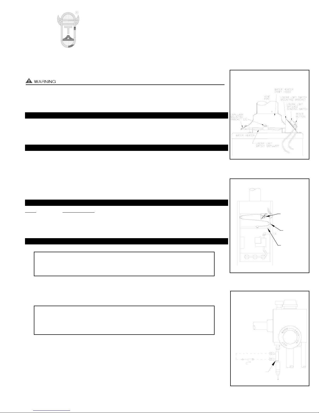
LINEAR LIMIT INSTALLATION
1. Shut off fuel supply to the appliance.
2. Attach Linear Limit spillage sensor to draft hood (A1) or diverter (A2), see respective diagram.
3. 30 Millivolt water heaters require the 950-0470, Thermocouple Junction Adapter. Unscrew
thermocouple from gas valve and screw in Thermocouple Junction Adapter. Screw thermocouple into Thermocouple Junction Adapter. Connect Linear Limit cables to spade connections on Thermocouple Junction Adapter, (see Diagram B). On 750 Millivolt (power pile)
heaters, wire Linear Limit spill switch in series with high limit (ECO) of heater.
4. Using cable routing tabs from wire routing packet, attach Linear Limit control cable to appliance maintaining a safe distance from hot surfaces, e.g. appliance vent pipe and hot water
pipes.
JUNCTION ADAPTER
THERMOCOUPLE
950-0470 (JA1)
LINEAR LIMIT
SPILL SWITCH
GAS
VALVE
ROUTING
CLIP
SWITCH
LINEAR LIMIT
DRAFT
DIVERTER
IMPORTANT:
DO NOT CUT THE COPPER CAPILLARY SENSING TUBE OR LIMIT WILL BE
DESTROYED AND APPLIANCE WILL BE DISABLED.
IMPORTANT:
Copper capillary sensing tube should not come in direct contact with metal surfaces.
Linear Limit spillage sensor should be mounted so that capillary will sample temperature of gases spilling from vent or chimney, not temperature of metal surface.
DIAGRAM A1
DIAGRAM B
DIAGRAM A2
TJERNLUND PRODUCTS, INC.
1601 Ninth Street • White Bear Lake, MN 55110-6794
PHONE (800) 255-4208 • (651) 426-2993 • FAX (651) 426-9547
Visit our web site • www.tjernlund.com
Page 2
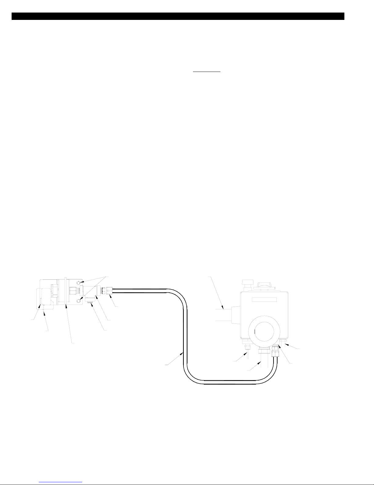
GAS PRESSURE SWITCH INSTALLATION
The gas pressure switch is mounted on the casing of the water heater adjacent to the heater's thermostat/gas control valve. It should be
mounted close enough so that the supplied 1/4" tubing will reach from the gas pressure switch fitting to the thermostat/gas valve pressure tap port. The two provided screws are self-tapping and drilling. The screws do not require the use of a drill and their 1/2" length
assures that the inner tank will not be penetrated.
1. Mount the gas pressure switch by securing it to the heater casing with a screw in each of the two mounting holes.
IMPORTANT: Mount gas pressure switch so that diaphragm is in a VERTICAL
position, (See Diagram C).
2. Install the supplied 1/8"-NPT pipe plug to the 90
o
port of the supplied 1/8-NPT black pipe tee, (See Diagram C).
Use thread sealant, do not over tighten.
3. Install the 1/8-NPT black pipe tee to the gas pressure switch, (See Diagram C). Use thread sealant, do not over
tighten. CAUTION: Utilize the hex nut on the gas pressure switch when attaching the black pipe tee.
4. Install the supplied Brass 1/8-NPT male x ¼" compression fitting to the 1/8-NPT black pipe tee, (See Diagram C).
Use thread sealant, do not over tighten.
5. Remove the PRESSURE TAP plug from the underside of the thermostat/gas control valve and install the supplied Brass
1/8-NPT male x ¼" compression fitting, (See Diagram C). Use thread sealant, do not over tighten.
IMPORTANT: DO NOT alter the heater's PILOT GAS LINE, (See Diagram C).
6. Using a tube cutter, cut the appropriate length of the supplied 1/4" tubing to reach from the gas pressure switch fitting to the
PRESSURE TAP PORT fitting of the thermostat/gas control valve. Make sure each end of the tubing is not pinched closed.
7. Use the 1/4" tubing to connect gas pressure switch fitting to the PRESSURE TAP PORT fitting on the thermostat/gas control valve.
8. Conduct a gas leakage test of all connections as outlined in the latest edition of NFPA 54, ANSI Z223.1, part 4. or local codes.
NOTE: A "gauge port" can be accessed by removing the 1/8-NPT pipe plug that is on the 1/8-NPT black pipe tee (attached to
the gas pressure switch).
DO NOT ALTER
GAS SUPPLY
INTO PRESSURE TAP PORT.
GAS PRESSURE SWITCH
GAS CONTROL VALVE
THERMOSTAT/
PILOT GAS LINE
FIGURE 700S107 2/13/04
INSTALL BRASS 1/8-NPT MALE
x 1/4" COMPRESSION FITTING
THERMOCOUPLE
BURNER GAS LINE
COMMON
MUST BE MOUNTED VERTICALLY.
GAS PRESSURE SWITCH DIAPHRAGM
IMPORTANT:
BRASS 1/8-NPT MALE x 1/4"
COMPRESSION FITTING
THERMOSTAT / GAS CONTROL
TO PRESSURE TAP FITTING OF
1/4" OUTSIDE DIAMETER
ALUMINUM TUBING - CONNECT
VALVE.
1/8-NPT BLACK PIPE TEE
1/8-NPT PIPE PLUG - NEW
PRESSURE TAP PORT
NORMALLY OPEN
MOUNTING HOLES
IMPORTANT:
DIAGRAM C
Page 3
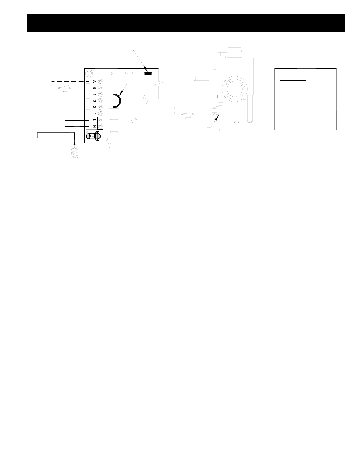
UC1 UNIVERSAL CONTROL, MAC1E OR MAC4E AND WHKE INTERLOCK KIT
CONNECTED WITH A MILLIVOLT APPLIANCE
XN
R
UNIVERSAL CONTROLLER
D/N 9183046-9
CALL
AS APPLIANCE INTERLOCK VOLTAGE.
RED JUMPER POSITION MUST BE THE SAME
XL
J1J2
DRY
115V
24V
IMPORTANT:
JUMPER
GENERATED
5 VDC
LEGEND:
115 VAC
WHKE GAS
SAFETY CIRCUIT ACROSS P1 & P2 OF UC1 IS NOT UTILIZED
WITH HEATING EQUIPMENT AS SHOWN.
IN THIS APPLICATION. SPILL SWITCH MUST BE INTERLOCKED
MILLIVOLT
PRESSURE
SWITCH
JUNCTION ADAPTER
THERMOCOUPLE
950-0470 (JA1)
LINEAR LIMIT
SPILL SWITCH
GAS
VALVE
30 MILLIVOLT WATER HEATERS REQUIRE USE OF THE
(ECO) OF WATER HEATER. LINEAR LIMIT SPILL SWITCH,
ON 750 MILLIVOLT (POWER PILE) WATER HEATERS WIRE
LINEAR LIMIT SPILL SWITCH IN SERIES WITH HIGH LIMIT
950-0470 THERMOCOUPLE JUNCTION ADAPTER.
950-0470 JUNCTION ADAPTER AND GAS PRESSURE
SWITCH ARE INCLUDED WITH WHKE KIT.
DO NOT
SUPPLY
POWER.
POWER!
BOARD-
50/60 Hz
SUPPLY
115 VAC
ELECTRICAL BOX.
GROUND
CRIMP GROUND WIRE TO GRO
UNDING SPADE TERMINAL IN
IMPORTANT:
CONNECTIONS WITH UC1, MAC1E OR MAC4E
Each millivolt appliance interlocked with the UC1, MAC1E or MAC4E must have its own WHKE kit installed. The WHKE Gas Pressure
Switch actuates the Venter through the A - B Dry contacts. The Linear Limit switch disables the heater in the event of a venting malfunction. IMPORTANT: Each millivolt appliance interlocked with the UC1, MAC1E or MAC4E must have its own Linear Limit spill switch.
1. Wire WHKE Gas Pressure Switch across A and B terminals on UC1, MAC1E or MAC4E. Do not supply voltage to A and B terminals.
2. Wire WHKE Linear Limit in series with thermocouple junction adapter or high limit ECO of heater.
3. Make sure RED voltage jumper on UC1, MAC1E or MAC4E is in the DRY position.
4. If not previously completed, connect 115 VAC supply voltage to L & N terminals on UC1. Crimp Ground wire to grounding spade
terminal in UC1. Important: Installer must supply overload and disconnect protection.
5. If not previously completed, connect ground from UC1 whip to Venter ground. Connect Black and White leads from UC1 whip
to Venter motor leads. Connect Blue and Yellow leads from UC1 whip to Venter Fan Prover switch. Prover Leads are not polarity
sensitive. If using a Draft Inducer and only venting millivolt appliances the PS1505 Fan Proving Switch is not necessary, see below
for further information.
DRAFT INDUCERS WITH ONLY MILLIVOLT APPLIANCES (PS1505 FAN PROVER NOT REQUIRED)
When venting only millivolt gas control(s) with a draft inducer, the PS1505 fan prover is not necessary. It will, however, be necessary to
"jumper" the P1 and P2 terminals on the UC1 Universal Control. Remove the call jumper across J1 and J2 and place it across P1 and
P2 on the UC1. Deactivate the Prover Status Check circuit by pushing the #9 dip switch up, or to the "deactivated" position in the UC1
Universal Control. See “Prover Status Check Dip Switch Settings” in the Venter or UC1 instruction manual. The P1 & P2 proving switch
circuit of the UC1 cannot control the burner operation of a millivolt gas control. When using a WHKE millivolt interlock kit, the appliance
safety shutdown is accomplished by the Linear Limit spill switch which detects flue gas spillage. WARNING: The P1 & P2 proving
switch circuit must only be jumpered when venting strictly millivolt appliances where the safety is provided by the Linear Limit.
HS-SERIES POWER VENTERS WITH ONLY MILLIVOLT APPLIANCES (FAN PROVING SWITCH PROVIDED)
When venting only millivolt gas control(s) with an HS-Series power venter connect Fan Prover leads as outlined above in step 5. The fan
prover will not control the millivolt gas valve, but its inclusion is beneficial to proper sequencing of the UC1 control.
MULTIPLE APPLIANCE INTERLOCKS WITH A MILLIVOLT AND A 24 -115 VAC CONTROLLED APPLIANCE
When using a WHKE millivolt interlock kit the millivolt appliance safety shutdown is accomplished by the Linear Limit spill switch which
detects flue gas spillage. The P1 & P2 proving switch circuit of the UC1 Universal Control cannot control the burner operation of a millivolt gas control. When co-venting a 24-115 VAC gas control with a millivolt gas valve (i.e. furnace and water heater combo) the P1 &
P2 proving switch circuit only interlocks the 24-115 VAC gas control. The millivolt appliance safety shutdown is accomplished by the
Linear Limit spill switch which detects flue gas spillage. WARNING: Do not jumper the P1 & P2 proving switch circuit when
co-venting millivolt and 24 - 115 VAC gas valves.
Page 4

WHKE OPERATION CHECK
1. Confirm power is supplied to the UC1 Control. (LED #6 RED Version 4.06 or later) or (LED #5 RED Versions prior to 4.06 ) on UC1
should be on.
2. Initiate a call for heat on appliance WHKE is installed on. LED #1 (AMBER) on UC1, MAC1E or MAC4E should be on.
3. The UC1 motor relay will close and activate the Venter motor. LED #3 (GREEN) on UC1 should be on.
4. Burner should fire and (LED #2 BLUE Version 4.06 or later on UC1, Version F of MAC1E / MAC4E) or (LED #2 GREEN Versions
prior to 4.06 on UC1, or prior to Version F on MAC1E / MAC4E) should also be on.
Venter should operate simultaneously with burner ignition. Verify burner lights off properly.
WHKE SAFETY INTERLOCK TEST
IMPORTANT:
The Linear Limit switch must disable the heater in the event of a venting malfunction. The following procedure is necessary to confirm that
the appliance is disabled in the event of a venting malfunction.
1. Remove power to the UC1 Universal Control.
2. Adjust thermostat to call for heat.
3. Venter should not run with UC1 power removed, but the appliance should fire.
4. Flue gas spillage will emit from the draft hood or diverter. Linear Limit spillage sensor should open in less than two minutes, preventing
thermostat signal from reaching burner. If Linear Limit does not open, remove call for heat, reposition Limit and repeat steps 1-4.
5. Wait 2-3 minutes and push reset button on Linear Limit spill spill switch.
COMBUSTION AIR TEST
1. Close all doors and windows of the building. If appliance is installed in utility room or closet, close the entrance door to this room.
Close fireplace dampers. Turn on clothes dryer and all exhaust fans such as range hoods, bathroom exhausts and whole house
fans to maximum speeds.
2. Place in operation the appliance that the WHKE has been installed on. Set thermostat for continuous operation.
3. Allow fans and appliance to operate for 15 minutes.
4. Tripping of the Linear Limit Spillage Sensor circuit during the 15 minute appliance operation indicates an unsafe operating condition.
Check appliances for venting malfunction and check for adequate combustion air. Turn off fuel supply to appliance and DO NOT
OPERATE UNTIL UNSAFE VENTING CONDITION IS INVESTIGATED BY PROFESSIONAL CONTRACTOR OR UTILITY
SERVICE PERSONNEL.
5. Return all windows, doors and fans to their previous conditions of use.
NOTE: For further assistance contact Tjernlund Products, Inc. Customer Service Department at 1-800-255-4208. 7:30 AM-4:30 PM CST.
REV. A 04/06 © 2006 TJERNLUND PRODUCTS, INC. P/N 8504108
The Linear Limit spill switch is designed to alert the user to a potentially hazardous condition. It is not designed to, and
cannot replace regular chimney inspection, appliance servicing and combustion testing. DO NOT USE THE LINEAR
LIMIT AS A SUBSTITUTE FOR PROFESSIONAL APPLIANCE MAINTENANCE.
TJERNLUND LIMITED ONE YEAR WARRANTY
Tjernlund Products, Inc. warrants to the original purchaser of this product that the product will be free from defects due to faulty material or workmanship for a period of
(1) year from the date of original purchase or delivery to the original purchaser, whichever is earlier. Remedies under this warranty are limited to repairing or replacing,
at our option, any product which shall, within the above stated warranty period, be returned to Tjernlund Products, Inc. at the address listed below, postage prepaid.
THERE ARE NO WARRANTIES WHICH EXTEND BEYOND THE DESCRIPTION ON THE FACE HEREOF, AND TJERNLUND PRODUCTS, INC. EXPRESSLY DISCLAIMS LIABILITY FOR INCIDENTAL OR CONSEQUENTIAL DAMAGES ARISING FROM THE USE OF THIS PRODUCT. THIS WARRANTY IS IN LIEU OF ALL
OTHER EXPRESS WARRANTIES AND NO AGENT IS AUTHORIZED TO ASSUME FOR US ANY LIABILITY ADDITIONAL TO THOSE SET FORTH IN THIS LIMITED WARRANTY. IMPLIED WARRANTIES ARE LIMITED TO THE STATED DURATION OF THIS LIMITED WARRANTY. Some states do not allow limitation on how
long an implied warranty lasts, so that limitation may not apply to you. In addition, some states do not allow the exclusion or limitation of incidental or consequential
damages, so that above limitation or exclusion may not apply to you. This warranty gives you specific legal rights and you may also have other rights which may vary
from State to State. Send all inquiries regarding warranty work to Tjernlund Products, Inc. 1601 9th Street, White Bear Lake, MN 55110-6794. Phone (651) 426-2993 •
(800) 255-4208 • Fax (651) 426-9547 • Email fanmail@tjfans.com.
 Loading...