

TJERNLUND UC1 UNIVERSAL CONTROL (VERSION X.06) ADDENDUM 8505017 REV B 0705, UC1 X.06 User Manual
Page 1
IMPORTANT!!! UC1 BOARD VERSION X.06 UPDATES
LED INDICATOR LIGHTS
LED #1 (Amber) Appliance call for heat.
LED #2 (Blue) Safety circuit through P1 & P2 (Venter Fan Prover and/or High Limit). Indicates Venter prover is closed during run cycle.
Burner circuit is energized with Interlock Relay contact closure from terminal 3 to 4.
LED #3 (Green) Power switched to Venter motor from L to MTR & M.
LED #4 (Red) Status / Fault indicator.
LED #5 (Red) Used as a status indicator.
LED #6 (Red) 115 VAC power supplied to board.
P/N: 8505017 ©2005 TJERNLUND PRODUCTS, INC. ALL RIGHTS RESERVED REV. B 07/05
TJERNLUND PRODUCTS, INC.
1601 Ninth Street • White Bear Lake, MN 55110-6794
PHONE (800) 255-4208 • (651) 426-2993 • FAX (651) 426-9547
Visit our web site • www.tjernlund.com
IMPORTANT:
For 950-8804 UC1 Replacement Board Kits: If this is a 950-8804 UC1 board kit and you are replacing an existing UC1 board with this
new board, note Dip Switch settings on existing UC1 circuit board so that those same settings can be positioned on this replacement circuit
board. NOTE: Adhere appropriate included label over existing label in UC1 or SideShot electrical box. Also adhere "Checking Memory for
Last Fault Code" sticker on inside of UC1 or SideShot SS1 Series electrical box. On SS2 Series adhere to underside of electrical box.
For SideShot Series SS1 Models: The Pre-Cycle Prover Status Check is deactivated from the factory on the SS1 Series. Because of the
low set point of the SS1 Fan Prover (as low as .03" w.c.) cross winds may cause the Fan Prover to close prior to a call for heat. Activating the
Prover Status Check on the SS1 may cause nuisance lockouts. Important: Deactivate the Pre-Cycle Prover status check if installing this board
on a new or existing SS1 installation by pushing the #9 dip switch up or “ON” to disable.
For Draft Inducers with the UC1: Natural draft or winds may be sufficient to close the fan prover switch contacts prior to a call for heat
when using the PS1505 fan prover with a draft inducer. Keeping the Pre-Cycle Prover Status Check activated may cause nuisance lockouts.
Important: Deactivate the Pre-Cycle Prover status check if installing this board on a new or existing draft inducer installation by pushing the #9
dip switch up or “ON” to disable.
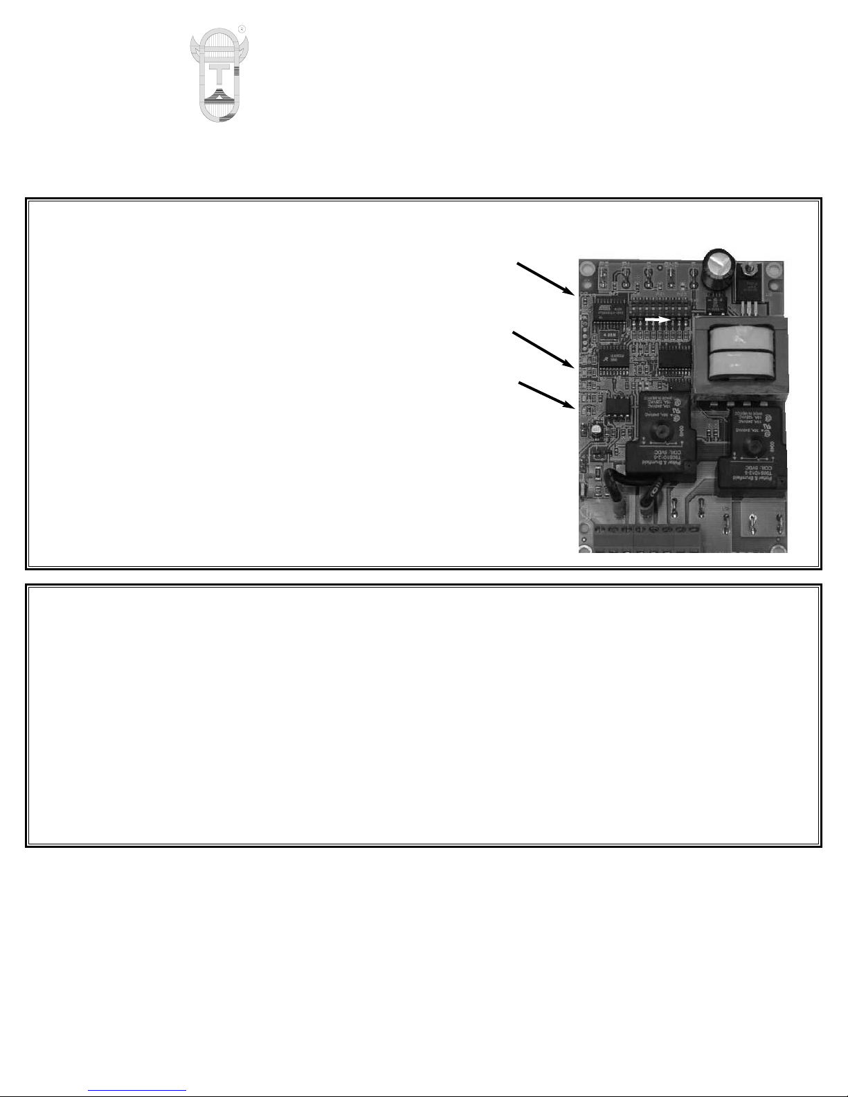
IMPORTANT: This upgraded circuit board features:
A new #6 power LED
Constant red when 115 VAC is supplied to L & N.
A new color for the #2 LED
Constant blue when fan prover safety circuit is closed.
A revised #5 LED
With no call for heat present, flashes 3 seconds on /
3 seconds off if microcontroller is working properly.
LED # 2 now BLUE
(previously GREEN)
New LED # 6 RED
115V power supplied
to UC1 L & N terminals
LED # 5 RED With no
call for heat, flashes 3
seconds on / 3 seconds
off if microcontroller is
working properly.
NEW X.06 VERSION UC1 BOARD FEATURES
LED 1 (AMBER)
LED 2 (BLUE)
LED 3 (GREEN)
LED 4 (RED)
LED 5 (RED)
LED 6 (RED) POWER LED
DRY
24 V
115 V
APPLIANCE
INTERLOCK
RELAY
VENTER
MOTOR
RELAY
A B 1 2 3 4 L N
J1 J2 XL XN
P1 P2 C GND F
(1 9)
N M MTR
Page 2
LED STATUS INDICATORS
LED #4 & #5 (Red) Flashing Alternately = Venter in Pre-purge. (Pre-Purge options 0, 5, 20, 35 seconds)
LED #4 & #5 (Red) Flashing in Unison = Venter in Post-Purge. (Post-Purge options 0, 30 seconds or 1, 2, 4, 8, 16 minutes)
LED #4 Flashes Continuously* = Fan Prover opened for more than 10 seconds during burner cycle.
(Venter will run for 10 minutes, attempting to make Fan Prover)
LED #5 (Red) Flashing Intermittently = With no call for heat, flashes 3 seconds on / 3 seconds off if microcontroller is working properly.
LED FAULT INDICATORS
Fault conditions are indicated by counting the number of times LED #4 (Red) flashes.
LED #4 Flashes 2 Times Fan Prover was in electrically closed position prior to venter operation.
LED #4 Flashes 3 Times* Fan Prover does not close within 60 seconds after call for heat.
LED #4 Flashes 4 Times* Fan Prover did not re-close after 10 minutes of Venter operation.
LED #4 Flashes 5 Times* Fan Prover opened for more than 10 seconds during burner cycle but closed within 10 minutes.
* Investigate cause of Fan Prover short cycling such as; Firing burner at capacities or temperatures exceeding Venter limits,
excessive vent pipe runs, elbows directly on venter discharge, high winds, plugged / kinked Fan Prover sensing tube or a faulty
Fan Prover switch. In-Forcer model’s intake screen and prefilter, if applicable, should be cleaned if necessary.
CHECKING MEMORY FOR LAST FAULT CODE
IMPORTANT: Prior to accessing the fault code memory, note the settings of the dip switches so that they can be returned to their original Pre /
Post-Purge positions. When power is supplied to the UC1 use caution when moving dip switches.
The last fault code can be retrieved at any time by setting all dip switches 1-8 to the up, or “on” position. The last fault code, or lack there of, will
be indicated by counting the number of times LED 4 flashes. By moving any of the dip switches back to their original position, the fault code will
be cleared. NOTE: The UC1 board must have its 115 VAC power supply present when any of the (1-8) dip switches are moved back to their
original position for the fault code to clear.
IMPORTANT: Fault codes will automatically be displayed after a fault condition occurs. If the call for heat interlock signal
or 115 VAC power is removed, the UC1 board will reset and the fault will be stored in memory instead of displayed. Any
new fault will replace any previous fault.
 Loading...