

TJERNLUND SS2 SIDESHOT (DISCONTINUED VERSION-PRE UC1 UNIVERSAL CONTROL) 8504063 REV B 1199, SIDESHOT SS2 Installation Instructions Manual
TJERNLUND PRODUCTS, INC.
1601 Ninth Street • White Bear Lake, MN 55110-6794
PHONE (651) 426-2993 • (800) 255-4208 • FAX (651) 426-9547
Visit our web site • www.tjernlund.com
MODEL SS2
REV. B 11/99
INSTALLATION INSTRUCTIONS
Recognize this symbol as an indication of important safety information!
!
OWNER INSTRUCTIONS, DO NOT DESTROY
CAUTION: The owner of the SS2 must keep the area around the vent terminal
!
free of snow, ice and debris.
NOTE: MAXIMUM FLUE GAS TEMPERATURES MUST NOT EXCEED 650oF
O
(343
TEM INLET.
THESE INSTRUCTIONS ARE INTENDED AS AN AID TO QUALIFIED, LICENSED SERVICE PERSONNEL FOR PROPER INSTALLATION, ADJUSTMENT AND OPERATION OF THIS UNIT.
READ THESE INSTRUCTIONS THOROUGHLY BEFORE ATTEMPTING INSTALLATION OR
OPERATION. FAILURE TO FOLLOW THESE INSTRUCTIONS MAY RESULT IN IMPROPER
INSTALLATION, ADJUSTMENT, SERVICE OR MAINTENANCE POSSIBLY RESULTING IN FIRE,
ELECTRICAL SHOCK, CARBON MONOXIDE POISONING, EXPLOSION, PERSONAL INJURY
OR PROPERTY DAMAGE.
C) MINIMUM TEMPERATURE MUST BE 250O F (121O C) AT VENT SYS -
NOTE: Burner capacities exceeding 1 GPH may require the burner to be adjusted to more
efficient (12.5-13% CO2) than typical levels to maintain recommended over-fire draft
settings. See “Draft Adjustment Procedure” on page 12 of this manual or consult
factory at 1-800-255-4208 with questions prior to installation.
DO NOT DESTROY. PLEASE READ CAREFULLY AND
KEEP IN A SAFE PLACE FOR FUTURE REFERENCE.
Copyright © 1999, Tjernlund Products, Inc. All rights reserved. P/N 8504063

Tjernlund Products welcomes your comments and questions.
Address all correspondence to:
Customer Service
Tjernlund Products, Inc.
1601 Ninth Street
White Bear Lake, MN 55110-6794
Call us toll free at 800-255-4208, visit our web site @ www.tjernlund.com or E-mail us at fanmail@tjfans.com.
TABLE OF CONTENTS
Page (s)
Description and Specifications ....................................................................................................................................1, 2
Installation Restrictions .................................................................................................................................................2
Cautions .........................................................................................................................................................................3
Safety Inspection of a Previously Used Oil Appliance ....................................................................................................3
SideShot®Model SS2 Terminology ................................................................................................................................3
Vent Hood Termination Clearances
U.S. Installations...............................................................................................................................................4
Canadian Installations......................................................................................................................................5
Installation
Tools Required .................................................................................................................................................5
Vent System Installation ..........................................................................................................................6, 7, 8
Installation of Vent Pipe ....................................................................................................................................8
Electrical Wiring
Wiring to Oil Fired Appliance ..............................................................................................................10, 11, 12
Draft Adjustment Procedure ............................................................................................................................12
Combustion Air............................................................................................................................................................. 13
Final System Operation Check Out ..............................................................................................................................13
Troubleshooting Oil Odors.............................................................................................................................................13
Troubleshooting Electrical Problems.......................................................................................................................14, 15
Maintenance..................................................................................................................................................................16
How to Obtain Service...................................................................................................................................................16
Warranty & Replacement Parts...............................................................................................................................16, 17
SS2 Vent Cabinet Mounting Template..........................................................................................................................18
SideShot® is a registered trademark of Tjernlund Products, Inc. for their Model SS2 Vent System.
DESCRIPTION
The SS2 is a mechanical vent system designed and listed for use with natural draft oil heating equipment. It is factory assembled
and wired. The SS2 automatically vents the flue gases from heating equipment to the outdoors. By recirculating indoor air with a
cooling fan, surrounding combustible materials remain at safe temperatures. After each burner cycle the SS2 will continue to
operate for an adjustable time period to purge the heater and vent of residual flue gases. The SS2 features a safety system consisting of a Fan Proving Switch and a High Limit temperature control. These devices monitor the SS2’s performance and will interrupt the main burner if a venting malfunction is detected.
APPLICATION TABLE
Verify that the total BTU/hr. input of the heating appliance(s) fall within the inputs listed below. The BTU/hr. capacity range is
based on a maximum of 50 equivalent feet (15 meters). To determine equivalent feet, add the total length of straight vent pipe
plus 10 feet (3 meters) for each 90 degree elbow and 5 feet (1.5 meters) for each 45 degree elbow. Vent runs of over 15 linear
feet (4.5 meters) require the use of an approved, insulated vent connector to prevent problems related to condensation.
The SS2 Vent System may only be used on Flame Retention Head Burners.
MODEL
SS2
Burner capacities exceeding 1 GPH may require the burner to be adjusted to more efficient (12.5-13% CO2) than typical levels
*
to maintain recommended over-fire draft settings. See “Draft Adjustment Procedure” on page 12 of this manual or consult
Tjernlund at 1-800-255-4208 with questions prior to installation.
Flame Retention
Oil Burner BTU/hr.
70,000-168,000
*
Max. Equivalent
Feet / Meters
50 feet
15 meters
1
SPECIFICATIONS
Motor: 115/1/60, 3000 RPM, 1/25 HP, 1.6 FLA, Ball Bearing Permanently Lubricated.
Fan Proving Switch: Non-adjustable set point of -.40” W.C. on pressure drop. Contacts rated for an inductive load of 6.2 FLA.
High Limit: Manual reset N/C contacts, open at 170oF + 8oF (77oC + 5oC). Contacts rated at 10 FLA at 120 VAC.
Post-Purge Timer: Adjustable from 1 to 10 minutes. Dual voltage, non-polarity sensitive input (24-120 VAC).
Cooling Fan: 115/1/60, RPM 3000-3300, AMPS .2, CFM 105, DB Level 50.
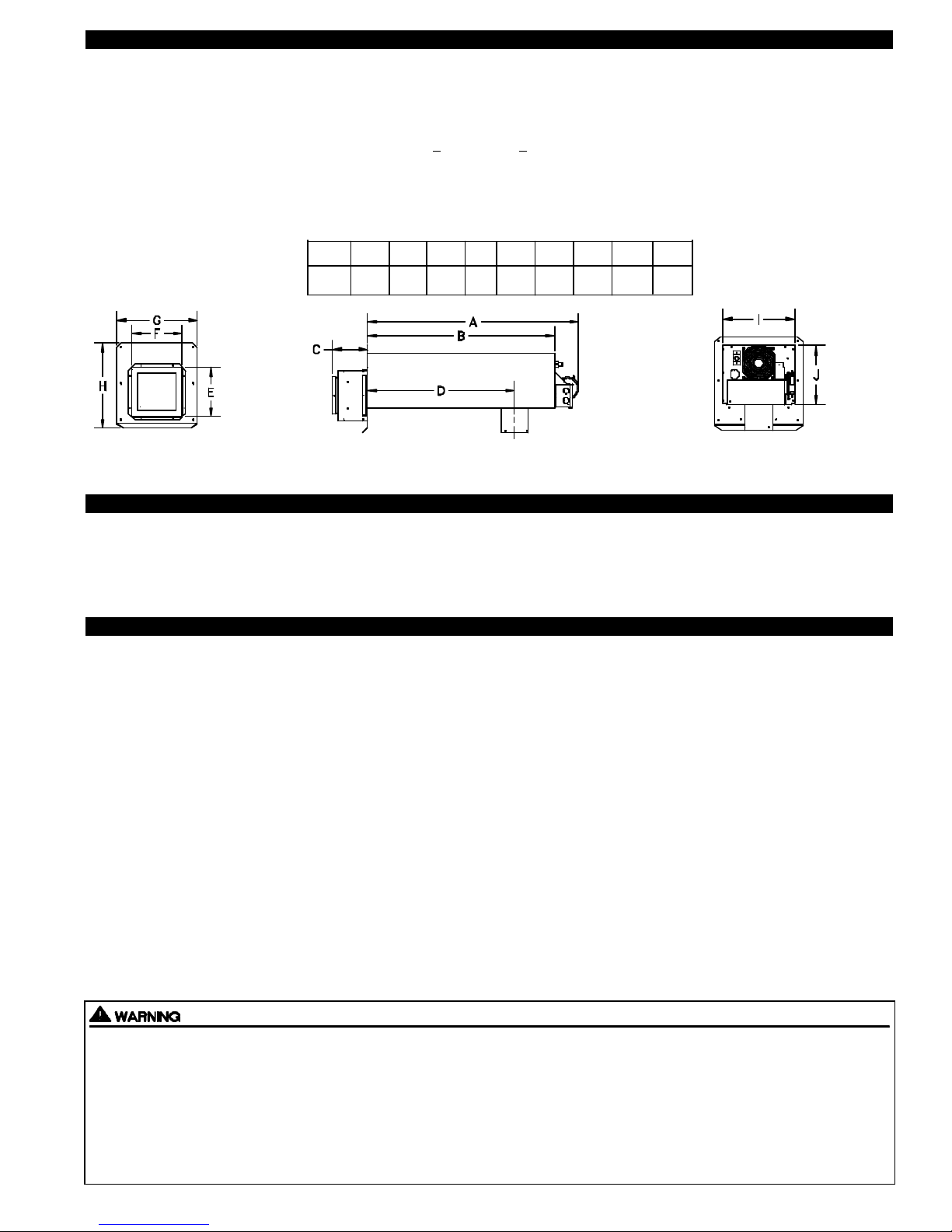
FRONT VIEW
A B C D E F
34 1/4” 28 1/2” 5 1/2” 22 3/8” 7 3/4” 8” 12 1/2”G13 1/4”H10 1/2”I8 1/2”
SIDE VIEW
J
REAR VIEW
GENERAL INFORMATION
Each SS2 is electrically factory line tested before shipment.
After opening carton, inspect thoroughly for hidden damage. Impeller should rotate freely. If any damage is found notify freight
carrier and your distributor immediately and file a concealed damage claim.
INSTALLATION RESTRICTIONS
1. The SS2 may not be installed on condensing type or solid fuel burning appliances, incinerators or incinerating toilets.
2. The SS2 may only be installed on Flame Retention Head Burners.
3. The SS2 may only be installed on appliances equipped with a barometric draft control.
4. The SS2 may not be connected to a natural draft chimney.
5. The SS2 shall not be installed where flue gas temperatures exceed 650oF (343oC) at its inlet. Flue gas temperature verification:
A) Verify flue gas temperature at appliance inlet is at or above 250oF (121oC) after 5 minutes of operation during setup. See
“Draft Adjustment Procedure” on page 12, step 9.
AND
B) After 15 minutes of operation, measure flue gas temperature to verify it is not more than 650oF (343oC) at SS2 inlet.
6. The electrical load controlled through the Fan Proving Switch must not exceed its nameplate ratings.
7. Vent runs of over 15 linear feet (4.5 meters) require the use of an approved, insulated vent connector to prevent problems related
to condensation.
Improper installation, adjustment, alterations, service or maintenance can cause injury, property damage or death. Refer to this
manual. For assistance or additional information consult a qualified installer, service agency or the equipment supplier.
Do not exceed the recommended input range of the SS2. Under no circumstances shall the minimum draft adjustment be used for
the larger input range of this product. Improper adjustment may result in the dispersion of flue products (carbon monoxide) into
the building interior causing carbon monoxide poisoning or death.
If oil nozzle is changed or other equipment is added perform “Draft Adjustment Procedure” on page 12 again.
2
CAUTIONS
1. Disconnect power supply from the SS2 and heating equipment when making wiring connections and servicing the SS2.
Failure to do so may result in personal injury and/or equipment damage.
2. Failure to install, maintain and/or operate the SS2 in accordance with manufacturer's instructions may result in conditions
which can produce bodily injury and property damage.
3. The SS2 must be installed by a qualified installer (an individual properly licensed and/or trained) in accordance with all
local codes or, in their absence, in accordance with the appropriate National Fire Protection Association #31, #211 and the
National Electrical Code. In the absence of local codes in Canada, installations must comply with CSA Std 139 (The National
Building Code of Canada) and CSA Std 22.1 (The Canadian Electrical Code).
4. Plan the vent layout so that the code required clearances are maintained from plumbing, wiring and combustible materials.
5. Flue gas temperatures must not exceed 650oF (343oC) at SS2 inlet. Ambient temperature must not exceed 104oF (40oC).
6 Flue gas temperature at vent system inlet must be at least 250oF (121oC) during appliance steady state.
7. Make certain power source is adequate for the SS2 requirements. Do not add the SS2 to a circuit when the total electrical load
is unknown.
8. "Safety Inspection of a Previously Used Appliance", below must be completed when replacing a conventional chimney
venting system or when SS2 is installed on used heating equipment.
SAFETY INSPECTION OF A PREVIOUSLY USED OIL APPLIANCE
(Perform prior to SS2 installation)
The following procedure is intended as a guide to aid in determining that an appliance is properly installed and is in safe condition
for continuing use.
This procedure is based on central furnace and boiler installations and it should be recognized that generalized procedures
cannot anticipate all situations. Accordingly, in some cases deviation from this procedure may be necessary to determine safe
operation of the equipment.
a. This procedure should be performed prior to any attempt at modifications of the appliance or installation of the SS2.
b. If it is determined there is a condition which could result in an unsafe operation, the appliance should be shut off and the owner
advised of the unsafe condition.
The following steps should be followed in making the safety inspection:
1. Visually inspect the venting system and determine there is no blockage or restriction, leakage, corrosion or other deficiencies
which could cause an unsafe condition.
2. Inspect burner and primary control for proper operation.
3. Applicable only to furnaces: Inspect heat exchanger for cracks, openings or excessive corrosion. Check both the limit control
and fan control for proper operation.
4. Applicable only to boilers: Inspect for evidence of water or combustion product leaks. Determine that the water pumps are in
operating condition. Test low water cutoffs, automatic feed controls, pressure and temperature limit controls and relief valves in
accordance with the manufacturer's recommendations to determine that they are in operating order.
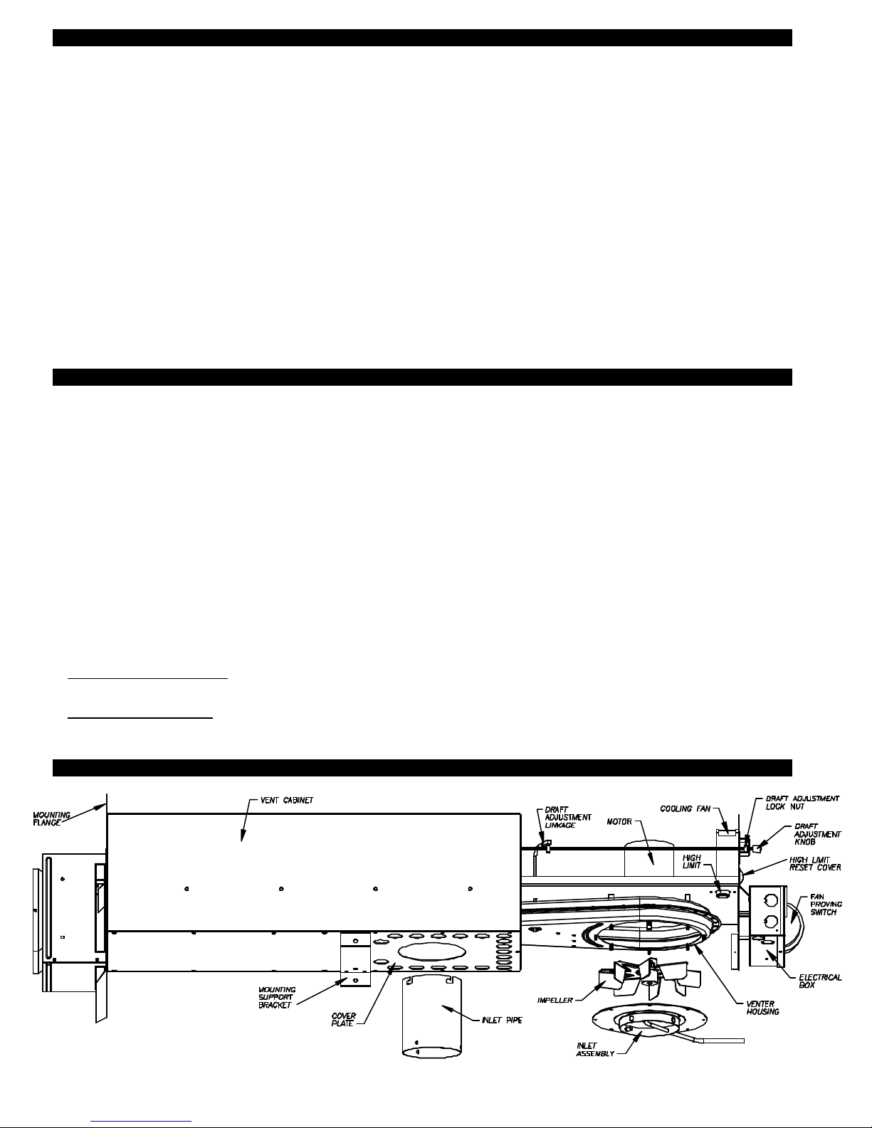
SIDESHOT®MODEL SS2 TERMINOLOGY
3
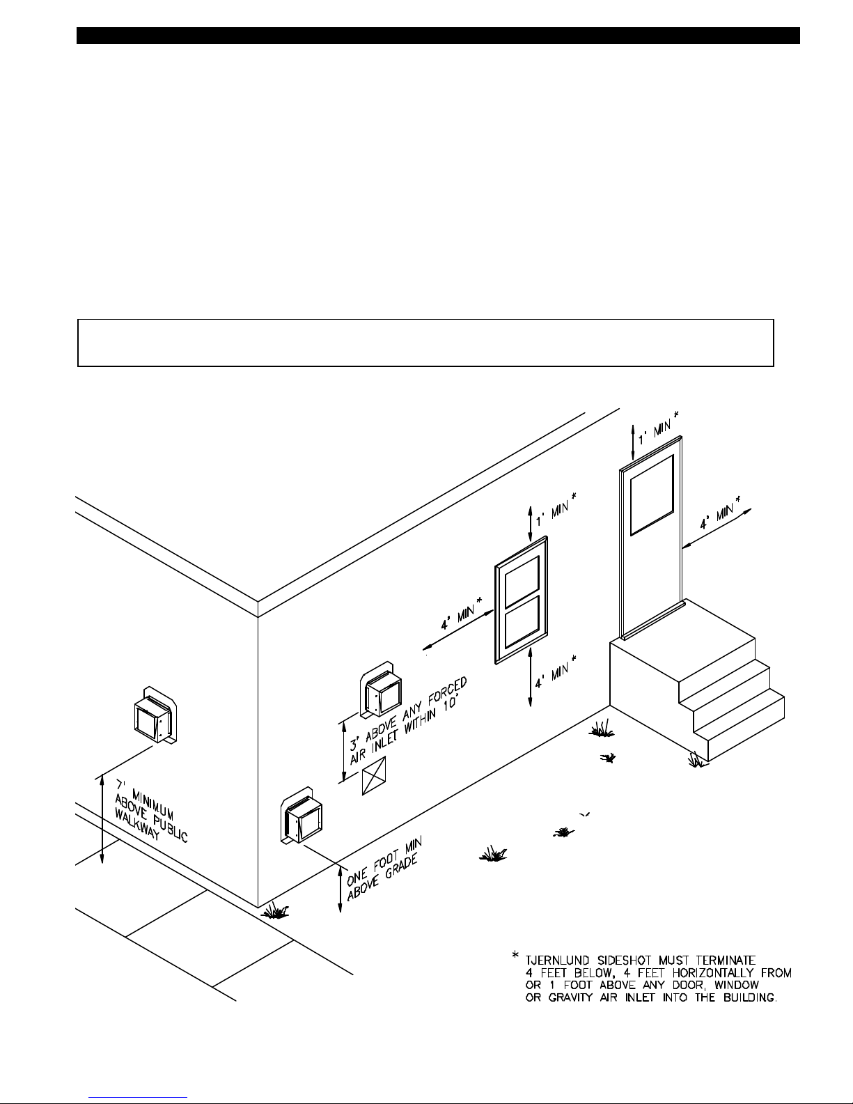
VENT HOOD TERMINATION CLEARANCES FOR U.S. INSTALLATIONS
The SS2 has been ETL Listed according to the requirements of the National Fire Protection Association #31, and #211 as follows
below, (See Diagram A).
• The exit terminals of mechanical draft systems shall not be less than 7 feet above grade when located adjacent to public walkways.
• A venting system shall terminate at least 3 feet above any forced air inlet located within 10 feet.
• The venting system shall terminate at least 4 feet below, 4 feet horizontally from or 1 foot above any door, window or gravity air
inlet into any building.
• The bottom of the vent terminal shall be located at least 12 inches above grade.
• The exit terminal shall be so arranged that the flue gases are not directed so as to jeopardize people, overheat combustible
structures or enter buildings.
• Not to be less than 10 feet from an adjacent building.
The SS2 is also Listed to terminate a minimum of 12” below, above or horizontally from a soffit, deck or adjacent sidewall.
CAUTION: The owner of the SS2 must keep the area around the vent terminal free of snow, ice and debris.
It is not recommended for the SS2 to be terminated on a wall that faces the direction of the prevailing winds.
Backdrafts by severe winds can cause oil odors to remain in the structure and/or interrupt equipment operation.
DIAGRAM A
4
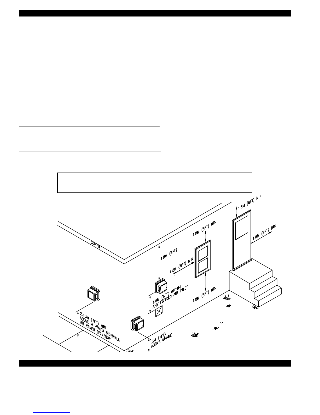
VENT HOOD TERMINATION CLEARANCES FOR CANADIAN INSTALLATIONS
The SS2 has been CSA Listed according to the requirements of “Mechanical Flue-Gas Exhausters” CSA Std B255-M81 and the
“Installation code for Oil burning Equipment” CSA Std B139-M91, (See Diagram A1).
• A venting system shall not terminate underneath a veranda, porch, or deck, or above a paved sidewalk or a paved driveway
that is located between two buildings, and that serves both buildings.
• The exit terminals of mechanical draft systems shall not be less than 2.13m (7ft) above grade when located adjacent to a paved
sidewalk or driveway.
• A venting system shall not direct flue gases towards brickwork, siding, or other construction, in such a manner that may cause
damage from heat or condensate from the flue gases.
• A venting system shall not direct flue gases so as to jeopardize people, overheat combustible structures, or enter buildings.
A venting system shall not terminate within 1.8 m (6ft) of the following:
• A window, door or mechanical air supply inlet of any building, including soffit openings
• A gas service regulator vent outlet
• A combustion air inlet
• A property line
• A direction facing combustible materials or openings of surrounding buildings
A venting system shall not terminate within 1m (3ft) of the following:
• Above a gas meter/regulator assembly within 1m (3ft) horizontally of the vertical centreline of the regulator
• A oil tank or an oil tankfill inlet
• The inside corner of an L-shaped structure
A venting system shall not terminate within .3m (1ft) of the following:
• Above grade level or any surface that may support snow, ice, or debris
CAUTION: The owner of the SS2 must keep the area around the vent terminal free of snow, ice and debris.
DIAGRAM A1
It is not recommended for the SS2 to be terminated on a wall that faces the direction of the
prevailing winds. Backdrafts by severe winds can cause oil odors to remain in the
structure and/or interrupt heating equipment operation.
• Nut Runner Set •Drill w/Bits • Combination Wrench Set
•Screwdriver Set •Wire Cutter/Stripper •Draft Gauge
•Smoke Tester •CO2 Analyzer • Reciprocating Saw
INSTALLATION TOOLSREQUIRED
5
 Loading...