

Page 1
TJERNLUND PRODUCTS, INC.
1601 Ninth Street • White Bear Lake, MN 55110-6794
PHONE (800) 255-4208 • (651) 426-2993 • FAX (651) 426-9547
Visit our web site • www.tjernlund.com
REV. 1 11/98
56826
MODEL SS2G
INSTALLATION INSTRUCTIONS
Recognize this symbol as an indication of important safety information!
!
OWNER INSTRUCTIONS, DO NOT DESTROY
NOTE: MAXIMUM FLUE GAS TEMPERATURES MUST NOT EXCEED 650oF.
THESE INSTRUCTIONS ARE INTENDED AS AN AID TO QUALIFIED, LICENSED SERVICE
PERSONNEL FOR PROPER INSTALLATION, ADJUSTMENT AND OPERATION OF THIS
UNIT. READ THESE INSTRUCTIONS THOROUGHLY BEFORE ATTEMPTING INSTALLATION OR OPERATION. FAILURE TO FOLLOW THESE INSTRUCTIONS MAY RESULT IN
IMPROPER INSTALLATION, ADJUSTMENT, SERVICE OR MAINTENANCE POSSIBLY
RESULTING IN FIRE, ELECTRICAL SHOCK, CARBON MONOXIDE POISONING, EXPLOSION, PERSONAL INJURY OR PROPERTY DAMAGE.
DO NOT DESTROY. PLEASE READ CAREFULLY AND
KEEP IN A SAFE PLACE FOR FUTURE REFERENCE.
Copyright © 1998, Tjernlund Products, Inc. All rights reserved P/N 8504075
Page 2
Tjernlund Products welcomes your comments and questions.
Address all correspondence to:
Customer Service
Tjernlund Products, Inc.
1601 Ninth Street
White Bear Lake, MN 55110-6794
or contact Tjernlund Products at 800-255-4208.
TABLE OF CONTENTS
Page (s)
Description and Specifications ....................................................................................................................................1, 2
Installation Restrictions .................................................................................................................................................2
Cautions .....................................................................................................................................................................2, 3
Safety Inspection of a Previously Used Gas Appliance ..................................................................................................3
SideShot®Model SS2G Terminology .............................................................................................................................3
Vent Hood Termination Clearances, Clearances to Combustibles & Obstructions .......................................................4
Installation
Tools Required .................................................................................................................................................5
Vent System Installation ..........................................................................................................................5, 6, 7
Installation of Vent Pipe ....................................................................................................................................7
Electrical Wiring
Wiring Restrictions ........................................................................................................................................7, 8
SS2G Wiring with Single Zone Thermostat.......................................................................................................8
Wiring to 24V Gas Valve...............................................................................................................................8, 9
Draft Adjustment Procedure ............................................................................................................................10
Combustion Air............................................................................................................................................................. 10
Final System Operation Check Out ..............................................................................................................................10
Troubleshooting Electrical Problems.......................................................................................................................11, 12
Maintenance..................................................................................................................................................................13
How to Obtain Service...................................................................................................................................................13
Warranty & Replacement Parts.....................................................................................................................................13
SS2G Vent Cabinet Mounting Template .......................................................................................................................14
SideShot® is a registered trademark of Tjernlund Products, Inc. for their Model SS2G Vent System.
DESCRIPTION
The SS2G is a mechanical vent system designed and listed for use with natural draft gas heating equipment. It is factory assembled and wired. The SS2G automatically vents the flue gases from heating equipment to the outdoors. By recirculating indoor air
with a cooling fan, surrounding combustible materials remain at safe temperatures. After each burner cycle the SS2G will continue
to operate for a nonadjustable timed period of approximately 45 seconds to purge the heater and vent of residual flue gases. The
SS2G features a safety system consisting of a Fan Proving Switch and a High Limit temperature control. These devices monitor
the SS2G’s performance and will interrupt the main burner if a venting malfunction is detected.
APPLICATION TABLE
Verify that the total BTU/hr. input of the heating appliance(s) falls within the inputs listed below. The BTU/hr. capacity range is
based on a maximum of 50 equivalent feet. To determine equivalent feet, add the total length of straight vent pipe plus 10 feet for
each 90 degree elbow and 5 feet for each 45 degree elbow. Vent runs of over 15 linear feet require the use of an approved, insulated vent connector to prevent problems related to condensation.
The SS2G Vent System may only be used on Natural or LP gas fired appliances.
MODEL
Fan Assisted
Natural & LP Gas
Atmospheric
Natural & LP Gas
Max. Equivalent
Feet
SS2G 40,000-125,000 BTU/hr40,000-150,000 BTU/hr 50
1
Page 3
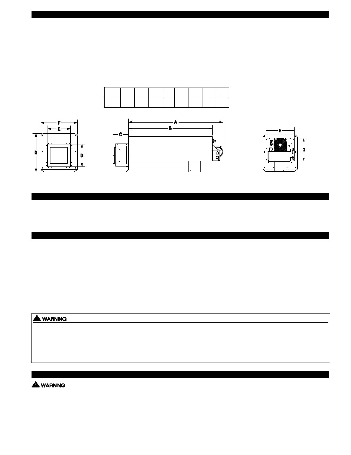
SPECIFICATIONS
Motor: 115/1/60, 3000 RPM, 1/25 HP, 1.6 FLA, Ball Bearing Permanently Lubricated.
Fan Proving Switch: Non-adjustable set point of -.40” W.C. on pressure drop. Contacts rated for an inductive load of 6.2 FLA.
High Limit: Manual reset N/C contacts, open at 170oF + 8oF. Contacts rated at 10 FLA at 120 VAC.
Post-Purge Timer: Nonadjustable 24 VAC input, approximately 45 second post-purge delay.
Cooling Fan: 115/1/60, RPM 3200, AMPS .2, CFM 105, DB Level 50.
A B C D E IHGF
34 1/4” 28 1/2” 5 1/2” 7 3/4” 8” 8 1/2”10 1/2”13 1/4”12 1/2”
FRONT VIEW SIDE VIEW REAR VIEW
GENERAL INFORMATION
Each SS2G is electrically factory line tested before shipment.
After opening carton, inspect thoroughly for hidden damage. Impeller should rotate freely. If any damage is found notify freight
carrier and your distributor immediately and file a concealed damage claim.
INSTALLATION RESTRICTIONS
1. The SS2G may not be installed on condensing appliances.
2. The SS2G may only be installed on appliances equipped with a draft hood, draft diverter or barometric draft control.
3. The SS2G shall not be installed where flue gas temperatures exceed 650oF at its inlet. Flue gas temperature verification:
A) After 15 minutes of operation, measure flue gas temperature to verify it is not more than 650oF at SS2G inlet.
4. The electrical load controlled through the Fan Proving Switch must not exceed its nameplate ratings.
5. Vent runs of over 15 linear feet require the use of an approved, insulated vent connector to prevent problems related to condensation.
Improper installation, adjustment, alterations, service or maintenance can cause injury, property damage or death. Refer to this
manual. For assistance or additional information consult a qualified installer, service agency or the equipment supplier.
Do not exceed the recommended input range of the SS2G. Under no circumstances shall the minimum draft adjustment be used
for the larger input range of this product. Improper adjustment may result in the dispersion of flue products (carbon monoxide)
into the building interior causing carbon monoxide poisoning or death.
CAUTIONS
The Power Venter must be installed by a qualified installer in accordance with these instructions and all local codes or in their
absence in accordance with the latest edition of The National Fuel Gas Code (NFPA #54), the latest edition of the National
Electrical Code (NFPA#70) and the Occupational Safety and Health Act (OSHA) when applicable. Improper installation can create
a hazardous condition such as an explosion, fire, electrical shock or carbon monoxide poisoning resulting in property damage, personal injury or death.
2
Page 4
Disconnect the power supply when making wiring connections or when working around the fan wheel and motor. Failure to do so
3
can result in electrical shock, personal injury, death or property damage.
1. “Qualified Installer” shall mean an individual properly trained and licensed.
2. Plan the vent system so that Code required distances are maintained from plumbing and wiring.
3. Make certain the power supply is adequate for the fan motor requirements. Do not add the Power Venter to a circuit where the
total load is unknown.
4. The installer must verify that the BTU/hr. input of the appliance does not exceed the recommended input of the SS2G. See
Application Table on page 1 of these instructions for sizing information.
5. Flue gas temperatures must not exceed 650 degrees F at the Power Venter inlet. Ambient temperatures must not exceed 104
degrees F. Temperatures above this range can cause a fire resulting in property damage, personal injury or death.
6. “Safety inspection of a previously used gas appliance” as outlined below must be performed before installation of the SS2G as
outlined in ANSI Z223.1/NFPA #54, Appendix H.
7. The electrical load controlled through the Fan Proving Switch must not exceed the electrical ratings marked on the Fan Prover.
Improper installation, adjustment, alterations, service or maintenance can cause injury or property damage. Refer to this
manual. For assistance or additional information consult a qualified installer, service agency or the gas supplier.
*SAFETY INSPECTION OF A PREVIOUSLY USED GAS APPLIANCE
(Perform prior to SS2G installation)
The following procedure is intended as a guide to aid in determining that an appliance is properly installed and is in safe condition
for continuing use.
The following procedure is based on central furnace and boiler installations and it should be recognized that generalized procedures cannot anticipate all situations. Accordingly, in some cases deviation from this procedure may be necessary to determine
safe operation of the equipment.
a. Perform this procedure prior to any attempt at modifications of the appliance or installation of the SS2G.
b. If it is determined there is a condition which could result in unsafe operation, shut off the appliance and advise the owner of the
unsafe condition.
Follow the steps below in making the safety inspection:
1. Conduct a gas leakage test of the appliance piping and control system downstream of the shutoff valve in the supply line to the
appliance.
2. Visually inspect the venting system and determine there is no blockage or restriction, leakage, corrosion and other deficiencies
which could cause an unsafe condition.
3. Shut off all gas to the appliance(s).
4. Inspect burners and crossovers for blockage and corrosion.
5. Applicable only to furnaces: Inspect heat exchanger for cracks, openings or excessive corrosion. Check both the limit control
and fan control for proper operation.
6. Applicable only to boilers: Inspect for evidence of water or combustion product leaks. Determine that the water pumps are in
operating condition. Test low water cutoffs, automatic feed controls, pressure and temperature limit controls and relief valves in
accordance with the manufacturer's recommendations to determine that they are in operating order.
* Excerpts from the National Fuel Gas Code (ANSI Z223.1/NFPA #54), Appendix H.
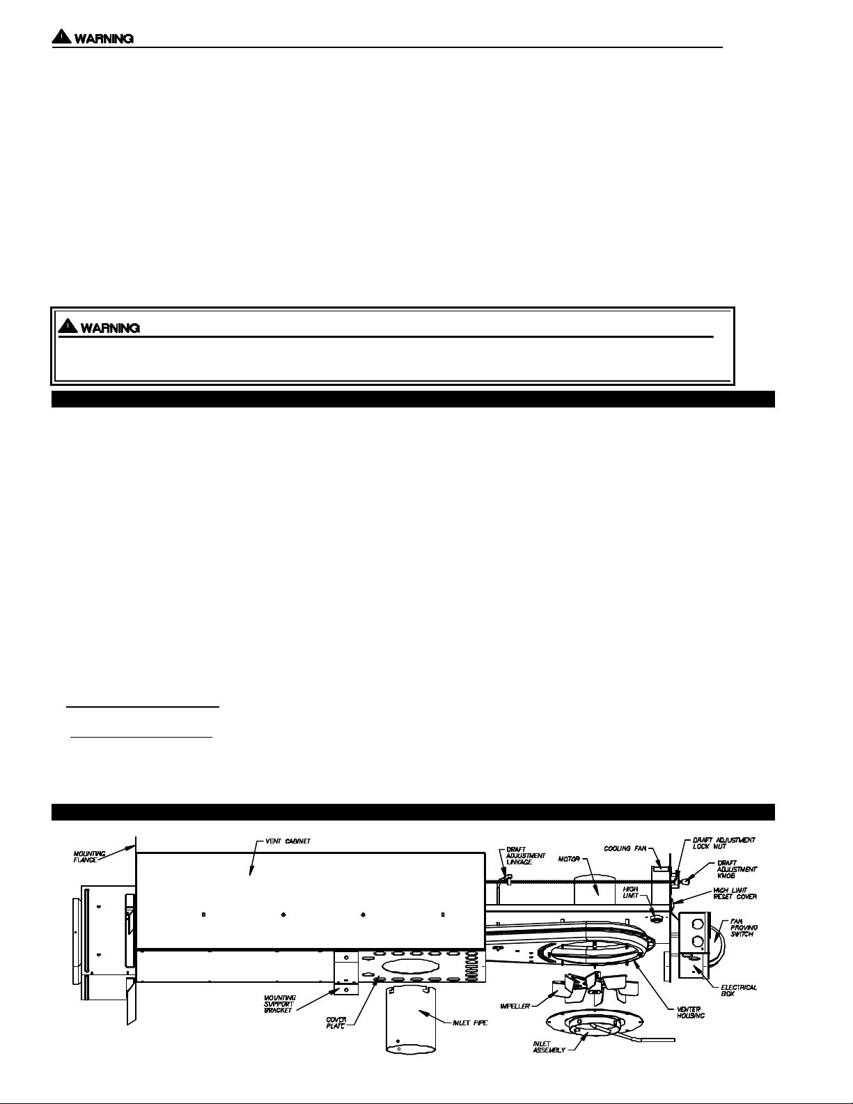
SIDESHOT®MODEL SS2G TERMINOLOGY
Page 5
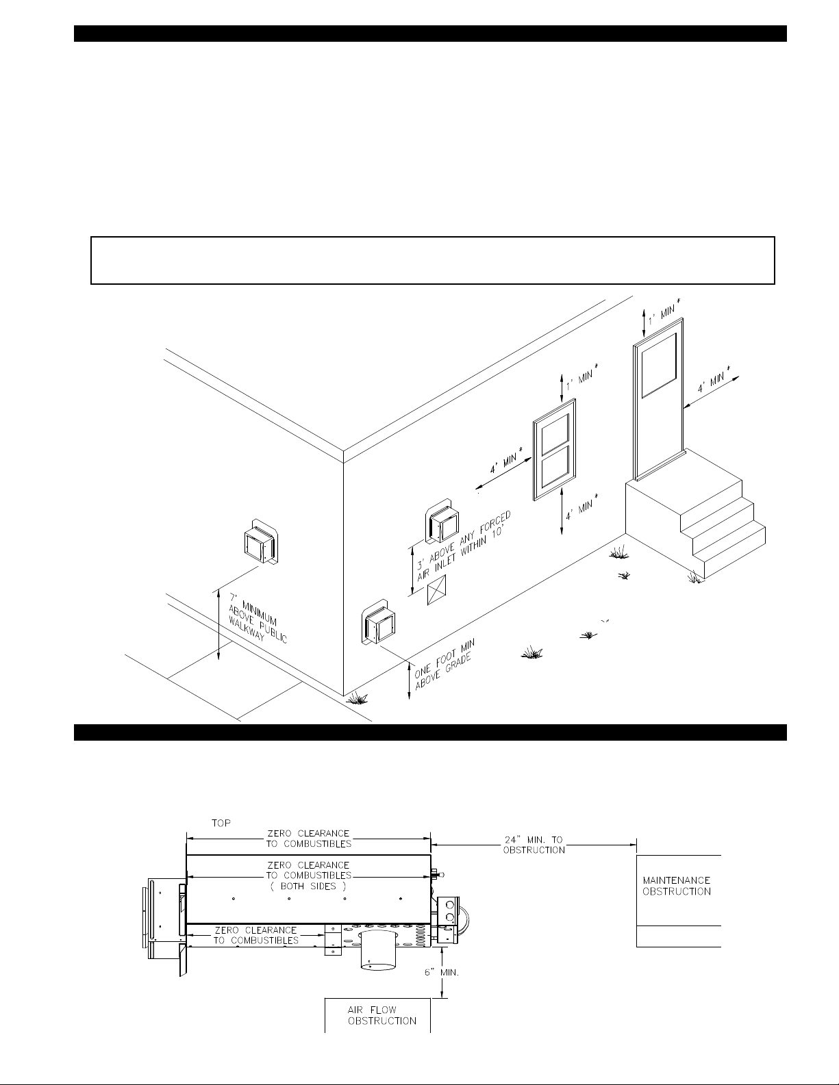
VENT HOOD TERMINATION CLEARANCES
The SS2G has been ETL Listed according to the requirements of the National Fire Protection Association #54, and #211 as
follows below, (See Diagram A).
• The exit terminals of mechanical draft systems shall not be less than 7 feet above grade when located adjacent to public walkways.
• A venting system shall terminate at least 3 feet above any forced air inlet located within 10 feet.
• The venting system shall terminate at least 4 feet below, 4 feet horizontally from or 1 foot above any door, window or gravity air
inlet into any building.
• The bottom of the vent terminal shall be located at least 12 inches above grade.
• The exit terminal shall be so arranged that the flue gases are not directed so as to jeopardize people, overheat combustible
structures or enter buildings.
• Not to be less than 10 feet from an adjacent building.
The SS2G is also Listed to terminate a minimum of 12 inches from soffits, decks or adjacent sidewalls.
It is not recommended for the SS2G to be terminated on a wall that faces the direction of the prevailing winds.
Backdrafts by severe winds can interrupt equipment operation.
DIAGRAM A
TJERNLUND SIDESHOT MUST TERMINATE
4 FEET BELOW, 4 FEET HORIZONTALLY FROM
OR 1 FOOT ABOVE ANY DOOR, WINDOW
OR GRAVITY AIR INLET INTO THE BUILDING.
SS2G VENT SYSTEM CLEARANCES FROM COMBUSTIBLES & OBSTRUCTIONS
With an inlet flue gas temperature of 650oF or below, the SS2G has been Listed for Zero Clearance from combustibles.
NOTE: You must allow a minimum 2 foot distance of unobstructed clearance behind the SS2G Vent System for
maintenance. Allow 6” minimum clearance from bottom of vent cabinet to any obstruction for air flow.
4
Page 6
INSTALLATION TOOLS REQUIRED
• Nut Runner Set •Drill w/Bits • Combination Wrench Set
•Screwdriver Set •Wire Cutter/Stripper •Draft Gauge
• Reciprocating Saw
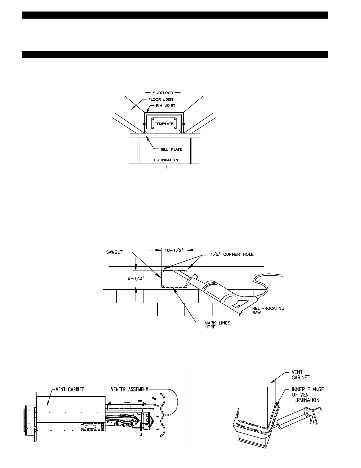
INSTALLING SS2G VENT CABINET
1. a) Fold SS2G Vent Cabinet template (Page 14) along dashed line and attach between the floor joists ensuring that it is snug
against the sill plate and centered between the floor joists. Follow same procedure if floor trusses are used, (See Diagram B).
b) If the SS2G is not being installed between floor joists, attach the template to the wall it will be exiting ensuring it is level.
DIAGRAM B
2. Verify that wall penetration will not come in contact with concealed wiring or plumbing. Using 1/2” bit, drill pilot holes noted on
each side of the template from inside through rim-joist, wall board, siding, etc., keeping drill bit perpendicular to the wall. 1/2" bit
must be long enough to penetrate through exterior.
3. Remove template from rim-joist and attach to building exterior, aligning pilot hole markings on template with holes previously
created in Step #2.
4. Drill remaining (4) corner holes noted on the template through the building exterior. Remove the template and mark lines from
the outside edge of the holes drilled, forming a rectangle.
5. Using reciprocating saw and appropriate blade, cut a rectangular opening through the rim joist, wall board, siding, etc., on the
lines marked in step 4. The rectangular opening should be no larger than 10-1/2" in width by 8-1/2" in height, (See Diagram C).
6. Knock out block material exposing rectangular opening through the wall.
DIAGRAM C
NOTE: For easy one person installations, remove (9) screws from rear and bottom of vent cabinet. Slide venter assembly out of
SS2G cabinet and set aside being careful not to damage housing. After SS2G cabinet is secured to the outside wall, and
the vibration isolation mount is installed to the inside wall, replace venter assembly and (9) screws, (See Diagram D).
7. Apply two beads of exterior rated caulk approximately 3/8" in width at the seam of the outside casing of the SS2G Vent Cabinet
and on the inner flange of the Vent Hood Termination, (See Diagram E).
DIAGRAM D DIAGRAM E
5
Page 7
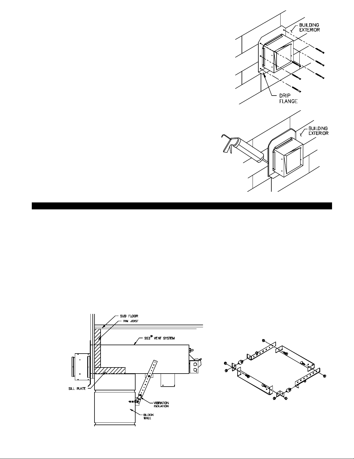
8. Slide the SS2G vent cabinet through the wall with drip
flange facing down towards ground, (See Diagram F).
Mount Vent Hood to exterior using (6) #10 x 1 1/4”
wood screws provided, (See Diagram F). If installing
in masonry wall drill 1/4” holes and use wall anchors
provided.
DIAGRAM F
9. After the SS2G is completely installed, apply a
bead of exterior rated caulk between the Vent
Hood Termination mounting flange and the
exterior of the building, (See Diagram G).
INSTALLATION OF WALL SUPPORT BRACKET
1. To prevent damage to the SS2G, temporarily support the bottom of the SS2G cabinet (prop on ladder top) while assembling the
wall support bracket. Assemble the wall support bracket as shown, (See Diagram H).
2. Connect mounting bracket to SS2G using (4) #8 x 3/8” sheet metal screws. Line up holes on bottom of SS2G with mounting
bracket to ensure proper placement, (See Diagram H).
3. Adjust the wall support bracket so that a slight pitch is maintained for moisture drainage and vibration isolation. Use the
prepunched holes on the wall bracket as a template to mark holes to be drilled into the side wall for mounting screws,
(See Diagram H).
DIAGRAM G
4. a) If installing the bracket into a wood wall, drill 2 pilot holes at each point established in step 3 with a 1/8" drill bit
approximately 1" deep and install the screws provided to secure the bracket to the wall.
b) If installing the bracket into a masonry wall, drill 2 holes at each point established in step 3 with a 1/4" masonry drill bit
Tap the masonry anchors into the 2 holes drilled and screw the wall bracket onto the wall.
DIAGRAM H
IMPORTANT:
Adjust SS2G mounting
bracket for slight pitch.
6
Page 8

INLET PIPE INSTALLATION
1. Remove 4” round inlet pipe from box.
DIAGRAM I
INSTALLATION OF VENT PIPE
The SS2G inlet is designed to accept 4” single wall or type “B” vent pipe. It will also accept 4” flexible vent connectors. The vent
pipe used must be in compliance with local codes and the listing of the vent pipe/connector manufacturer.
Always use a vent pipe/connector of the same diameter as the appliance flue outlet. Use a tapered reducer near the SS2G inlet
pipe if the appliance flue outlet is larger than 4”.
Determine vent pipe layout which will allow for the least amount of elbows to the appliance. Calculate the equivalent vent pipe
length from the appliance to the SS2G Vent System by adding the straight vent pipe length and the equivalent elbow lengths.
Each 90 degree elbow is equal to 10 feet of straight vent pipe, each 45 degree elbow is equal to 5 feet of straight pipe. The equivalent vent pipe length must not exceed 50 feet from the appliance to the SS2G Vent System. Vent runs of over 15 linear feet
require the use of an approved, insulated vent connector to prevent problems related to condensation. It is not necessary to maintain a 1/4" rise per foot of horizontal when Side Wall Venting.
NOTE: Installing a vent pipe “jog” on vertical vent pipe layouts allows for easier dismantling when servicing is necessary,
(See Diagram J).
DIAGRAM J
2. Align the 4 slots of the inlet pipe to the 3 pins and
proving switch sensing tube, push pipe up until it
bottoms out in the SS2G inlet.
3. Turn the inlet collar clockwise to lock in place,
(See Diagram I). IMPORTANT: After vent pipe
is installed verify inlet pipe is locked tightly in place.
NOTE “A”
Any vent pipe run that exceeds 15 linear
feet in length must use an approved,
insulated vent pipe. DO NOT EXCEED
50 EQUIVALENT FEET.
ELECTRICAL WIRING
All wiring from the SS2G to the appliance must be appropriate Class 1 wiring as follows: installed in rigid metal conduit, intermediate
metal conduit, rigid non-metallic conduit, electrical metallic tubing, Type MI Cable, Type MC Cable, or be otherwise suitably
protected from physical damage. Note: We recommend the use of flexible conduit for connections to the SS2G to allow for slide
out servicing feature of venter assembly.
The electrical contact ratings for the diaphragm Fan Proving Switch and High Limit are as follows:
FAN PROVING SWITCH HIGH LIMIT
3 Amps (full load) at 24 VAC 10 Amps (full load) at 24 VAC
36 Amps (locked rotor) at 24 VAC 60 Amps (locked rotor) at 24 VAC
The Fan Proving Switch and High Limit are not suitable for loads which exceed the above limits.
1. The installer must ensure that all electrical connections between the appliance and Power Venter are tight and that all wires are
positioned and secured so they cannot come in contact with high temperature locations. Use adequate conduit supports where
necessary.
2. The installer must ensure that the internal appliance transformer is rated no lower than 40VA.
Typical short vent pipe installation
7
Page 9
3. The installer must ensure that the heat anticipator in the comfort thermostat is adjusted according to the thermostat
manufacturer’s recommendation.
4. All wiring must be in compliance with local codes or in their absence, with the latest Edition of the National Electric Code (NFPA #70).
5. Disconnect 115V power before attempting to wire the Power Venter to the appliance. Power may be disconnected by means of
the appliance circuit breaker/fuse.
NOTES:
While it is impossible to include every possible wiring scenario, the following diagrams represent the most common. If wiring the
SS2G to an appliance not equipped with the controls shown on the following diagrams, determine which terminals of the gas
valve are considered “HOT” and “COMMON” and follow the steps on page 9.
When wiring Power Venter to the gas valve wire all thermostats, zones, circulators and limits as would normally be done if venting
into a chimney.
T PROCEDURES
SEQUENCE OF OPERATION WITH SINGLE ZONE THERMOSTAT:
Adjust the furnace thermostat to call for heat. The Power Venter should start. After a slight delay, the furnace burner should fire.
The delay is caused by the Power Venter fan proving switch. The delay will be no more than 4 seconds. If you are unable to
detect a slight delay, contact Tjernlund Products, Inc. at 1-800-255-4208 for assistance. When the fan proving switch closes, the
furnace combustion relay is energized. Normal combustion sequence for the furnace begins: induced draft furnace blower starts,
its proving switch makes energizing ignition control and/or gas valve. DO NOT OPERATE THE FURNACE WITHOUT THE FAN
PROVING SWITCH WIRED INTO THE 24V FURNACE CIRCUIT!
NOTE: When Power Venter is interlocked with a thermostat wire all zones, circulators and limits as would normally be done if
If you are unable to wire the SS2G as outlined in these instructions, call Tjernlund’s Customer Service Department toll free at
1-800-255-4208 for assistance.
NAT
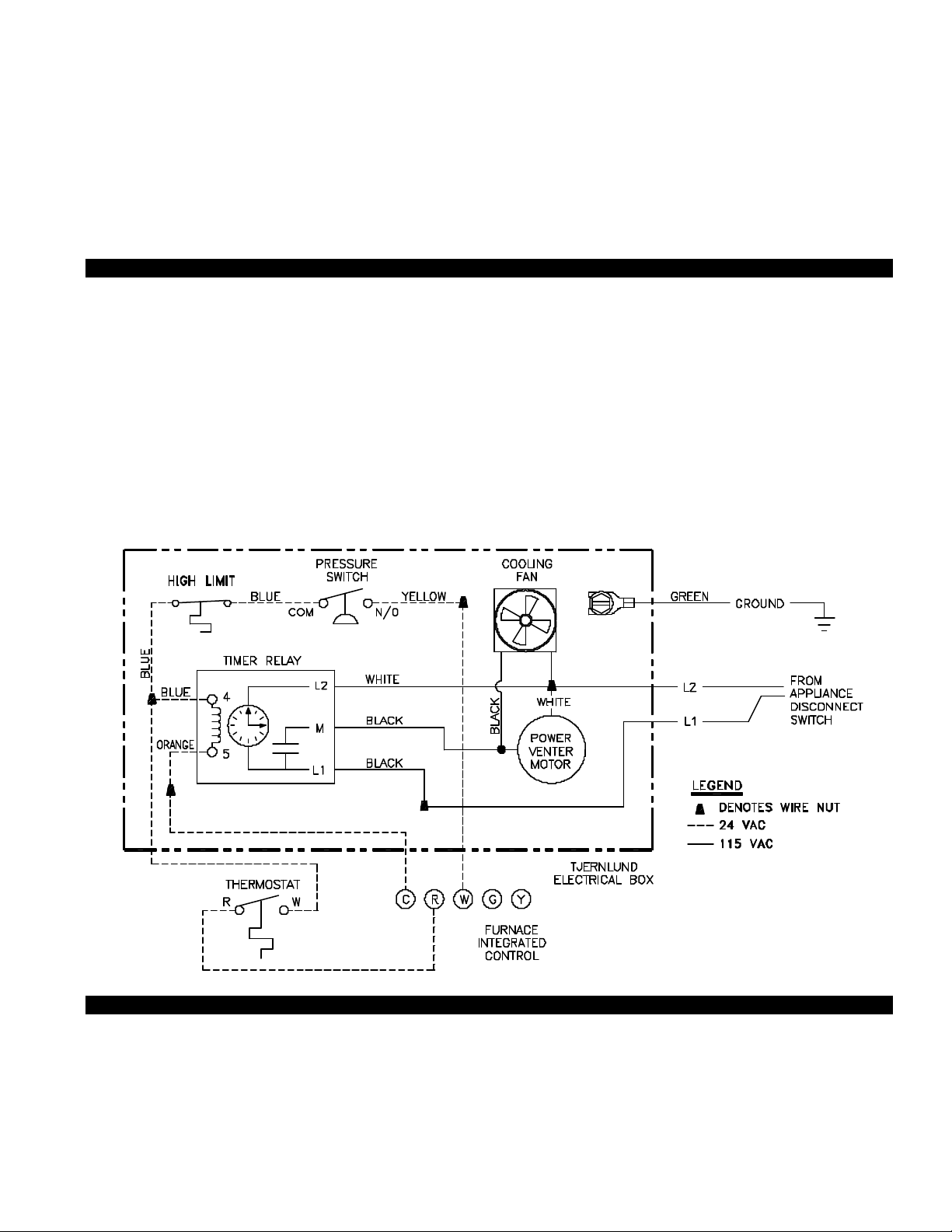
WIRING SS2G WITH SINGLE ZONE THERMOSTAT
venting into a chimney.
WIRING SS2G WITH THERMOSTAT
SS2G WIRED TO 24V GAS VALVE
SS2 SEQUENCE OF OPERATION WIRED TO GAS VALVE:
As the thermostat/aquastat senses a need for heat, the internal switch of the thermostat/aquastat will close. The Switch closure
completes the 24V electrical circuit to the internal controls of the appliance. Before the 24V signal reaches the appliance gas
valve, it is interrupted by the Power Venter Relay/Timer and Fan Proving Switch. When the Power Venter Relay/Timer receives
the 24V signal, the contact side closes completing the 115V circuit to the Power Venter motor. The air movement generated by
the Power Venter closes the Fan Proving Switch and completes the circuit to the appliance gas valve. The appliance gas valve
will only receive power when the appliance thermostat/aquastat is calling for heat and the Power Venter is operating. When the
appliance thermostat/aquastat is satisfied, 24V will be discontinued to the Relay/Timer and the Power Venter will continue to operate for a nonadjustable post purge period of approximately 45 seconds.
8
Page 10

9
Page 11

DRAFT ADJUSTMENT PROCEDURE
The SS2G Vent System will properly vent a wide range of BTU/hr. input capacities. To compensate for different burner capacities,
vent connector lengths, types and sizes, it features a draft adjustment located on the back of the venter assembly. Turning this
draft adjustment knob clockwise will increase draft and raise the BTU capacity. Turning knob counterclockwise will decrease draft
and lower the BTU capacity. The SS2G is factory set for the highest draft (BTU capacity).
IMPORTANT:
Before proceeding, close all windows, doors and fireplace dampers. Turn on all appliances in the structure that exhaust indoor air
such as clothes dryer, exhaust fans, range hoods, bathroom and whole house exhaust fans. Failure to perform the draft adjustment procedure may cause a poor vent system installation possibly resulting in fire, carbon monoxide poisoning, explosion, personal injury or property damage.
1. Place the heating system into operation. NOTE: there will be a slight pause between venter operation and burner operation. If
installation uses a barometric draft control adjust it to the minimum or least draft setting. Allow heater to operate for 5 minutes.
2. PREFERRED METHOD: MUST HAVE DRAFT GAUGE AVAILABLE
Sample draft one foot after draft hood, diverter or barometric draft control using a draft gauge. If the draft reading is in excess of
-0.05” W.C. turn the draft adjustment knob on the SS2G counterclockwise so that a draft reading of -0.02” to -0.05” W.C. is
obtained. Never adjust draft to a setting of less than -0.02” W.C. If the vent system is terminated on a wall subject to prevailing
winds a -0.05” W.C. draft setting is recommended.
3. If a draft gauge is not available test for spillage at the draft hood, diverter or barometric draft control using the flame from a
match, lighter or candle and determine the following:
A. The flame or smoke is being drawn into the draft hood, diverter or barometric draft control.
B. The main burner is burning properly, i.e. no floating, lifting or flash back.
DIAGRAM K
C. If the heater has a two stage or modulating gas valve verify that burner operates properly at
both low and high fire.
If the draft appears excessive turn the draft adjustment knob counterclockwise and repeat
steps A through C.
4. Lock the draft adjustment knob in place by tightening the locking nut behind the bracket,
(See Diagram K).
5. Turn off appliances and exhaust fans activated for draft adjustment procedure.
COMBUSTION AIR
Adequate combustion air is vital for proper combustion and for safe venting. Likewise, for proper SS2G performance, adequate
combustion air must be available to the appliance. Many installers assume adequate combustion air is present, especially in older
homes. In some cases this is a false assumption, because many older homes have been made "tight" due to weatherization. Size
the combustion air opening(s) into the appliance room as outlined NFPA 54/NFPA 211. When installing a SS2G, it is not necessary to supply any more combustion air than normally required when conventional venting. Common symptoms of inadequate
combustion air include: Fan Proving Switch short cycling, odor present at the end of burner cycle, outside air enters the structure
through the SS2G Vent System on SS2G/Appliance off cycle.
FINAL SYSTEM OPERATION CHECK-OUT
1. Adjust thermostat or appliance controls to call for heat.
2. Verify that the SS2G operates first, prior to burner ignition.
Allow heating equipment and SS2G to operate continuously while performing steps 3-5.
3. Close all doors and windows of the building. If heating equipment is installed in utility room or closet, close the entrance door to
this room. Close fireplace dampers.
4. Turn on all appliances in the structure that exhaust indoor air during their operation, e.g. turn on clothes dryer and exhaust fans
such as range hoods, bathroom exhaust and whole house fans.
5. Allow SS2G and equipment to operate for at least 15 minutes. Tripping of the burner circuit by the Fan Prover Switch during the
15 minute operation indicates an unsafe operating condition. Turn fuel supply off to appliance and DO NOT OPERATE
UNTIL UNSAFE VENTING CONDITION IS INVESTIGATED BY QUALIFIED SERVICE PERSONNEL.
6. Turn thermostat or equipment controls to the "off" position. Verify that the post-purge timer operates the SS2G for approximately
45 seconds while burner is not firing before the SS2G turns off.
7. Return all windows, doors and exhaust fans to their original conditions of use.
10
Page 12

TROUBLESHOOTING
The following guide is intended to be used if a problem occurs during the use of the SS2G side wall vent system. At several steps
throughout the guide you will be required to measure voltage with a voltmeter. Extreme caution must be exercised to prevent
injury. If you are unable to determine the defective part with the use of this guide, call your Tjernlund distributor or Tjernlund
Products direct at 1-800-255-4208 for further assistance.
NOTE: When 120 VAC is applied to SS2G terminals it may start up and run for up to 45 seconds. Do not initiate a call for heat
with the appliance until the SS2G is finished with its post purge time cycle.
SYMPTOM 1: POWER VENTER RUNS CONTINUOUSLY / ERRATICALLY
Step 1.
Confirm that thermostat is not
calling for heat.
No call for heat
Step 2.
With the Power Venter running, remove the ORANGE wire
on Relay/Timer terminal #5.
Result: Power Venter should shut off within approximately 45
seconds.
Yes
Step 3.
Reinstall the ORANGE wire on Relay. Verify thermostat is not calling for heat.
Interlocked directly with gas valve
Check for 24V across appliance control such as (Aquastat B1/B2), (Intermittent
Ignition Module MV - MV/PV) or (Standing Pilot TH - Hot & TR - Common).
Interlocked with thermostat at furnace
Check for voltage across W & C at thermostat.
24 Volts not present
Contact Tjernlund Products, Inc. for
additional assistance.
No
SYMPTOM 2: POWER VENTER DOES NOT RUN DURING CALL FOR HEAT
Step 1.
Activate thermostat to call for
heat. Check for 24V across
terminals 4 and 5 of the
Relay/Timer.
24V
24Volts
Not Present
Step 1.1
Interlocked directly with gas valve
Verify 24V across appliance control such
as (Aquastat B1/B2), (Intermittent Ignition
Module MV - MV/PV), or (Standing Pilot
TH - Hot & TR - Common) during call for
heat.
Interlocked with thermostat at furnace
Verify 24V across R & C on furnace terminal strip.
Solution: Replace Relay/Timer Part # 950-0014
non-adjustable or Part # 950-1067 adjustable
Relay/Timer.
24 Volts present
24V
No
Solution: Contact the appliance manufacturer for further assistance.
Step 1.2
Interlocked directly with gas valve
Check for loose connections between
appliance and Power Venter.
Interlocked with thermostat at furnace
Contact T-Stat manufacturer for further
assistance.
Step 2.
Remove 115V power source to
the Power Venter. Remove
the two BLACK leads from the
Relay and connect them
together. Reestablish 115V.
Result: Power Venter runs
continuously.
Yes
Solution: Replace Relay/Timer
Part # 950-0014 or Part #
950-1067 adjustable Relay/Timer.
No
Solution: Contact appliance manufacturer
for further assistance.
Solution: Replace Power Venter Motor.
Part # 950-0015.
11
Page 13

SYMPTOM 3: APPLIANCE WILL NOT OPERATE, BUT SS2G DOES
Step1.
Verify draft adjustment has been made.
Yes
Step 2.
With the appliance calling for heat and SS2G
operating, verify 24V exists between SS2G &
Orange leads.
No Voltage
Step 3.
Remove call for heat to SS2G. Check Fan Proving
Switch tube for clear passage.
Tube is Clear
Step 4.
With SS2G running, verify adequate draft at Fan
Proving Switch. Draft Gauge should read -.45"
w.c. minimum at Fan Proving Switch Test Port.
Yes
No
24 V
No
No
Set draft adjustment according to "Draft
Adjustment Procedure" on page 10.
SS2G and appliance are not interlocked
correctly or malfunction of appliance controls.
Refer to electrical diagrams in this manual and
appliance manufacturer's troubleshooting
guide.
Remove inlet assembly tubing blockages or
crimps in silicone tubing connection. Replace
tubing if necessary.
Check firing rate of appliance and "equivalent"
vent pipe length. They should not exceed the
maximum capacity of the SS2G. See
“Application Table” on page 1.
Step 5.
Remove call for heat to SS2G. Remove the BLUE
and YELLOW wires from SS2G Proving Switch.
Activate thermostat to call for heat. With SS2G
running, check for continuity across the COM and
N/O terminals of Fan Proving Switch. Result:
Contacts on switch should be closed.
Yes
Step 6.
Replace BLUE to COM and YELLOW to N/O
on Fan Proving Switch. With appliance calling
or heat, verify that the cooling fan is operational with SS2G.
Yes
Step 7.
Reset the SS2G High Limit by depressing the
button located on the center of the switch.
Appliance should operate.
Yes
No
No
No
Replace Fan Proving Switch
Part # 950-0016.
Replace Cooling Fan if it will not operate.
Part # 950-0020. After cooling fan has been
replaced reset SS2G High Limit by depressing button located on the center of the
switch.
Replace High Limit Switch
Part # 950-0018.
CAUTION: Do not operate appliance until source
of excessive heat has been determined. Check
for Vent Hood blockage or burner malfunction.
12
Page 14

MAINTENANCE
INSTALLER AND USER REQUIREMENTS
A vent system inspection must be performed annually by a qualified service agency. The inspection should include the operation
circuit check, safety interlock test, combustion air test and a visual inspection of the complete vent system for corrosion, blockage
or leaks. Any corrosion, blockage or leaks detected must be repaired or replaced immediately.
MOTOR OILING
The SS2G Motor has sealed ball bearings and requires no oiling.
HOW TO OBTAIN SERVICE ASSISTANCE
1. If you have any questions about your Power Venter or if it requires adjustment, repair or routine maintenance, we suggest
that you contact your installer, contractor or service agency.
2. If you require technical information contact Tjernlund Products, Inc. at 1-800-255-4208.
When contacting Tjernlund Products, Inc., please have the following information available:
1. Model of the Power Venter as shown on the label attached to Power Venter.
2. Name and address of installer and any service agency who performed work on Power Venter.
3. Date of original installation and dates any service work was performed.
4. Details of the problem as you can best describe them.
LIMITED PARTS WARRANTY AND CLAIM PROCEDURE
Tjernlund Products, Inc. warrants the components of the SideShot for two years from date of installation. This warranty covers
defects in material and workmanship. This warranty does not cover normal maintenance, transportation or installation charges for
replacement parts or any other service calls or repairs. This warranty DOES NOT cover the complete SS2G if it is operative,
except for the defective part.
Tjernlund Products, Inc. will issue credit or provide a free part to replace one that becomes defective during the two year warranty
period. If the part is over 30 months old, proof of date of the installation in the form of the contractor sales/installation receipt is
necessary to prove the unit has been in service for under two years. All receipts should include the date code of the SideShot to
ensure that the defective component corresponds with the complete unit. This will help preclude possible credit refusal.
1.) Follow troubleshooting guide to determine defective component. If unable to determine faulty component, contact your
Tjernlund distributor or Tjernlund Products Technical Customer Service Department at 1-800-255-4208 for troubleshooting
assistance.
2.) After the faulty component is determined, return it to your Tjernlund distributor for replacement. Please include SideShot date
code component was taken from. The date code is located on the Electrical Box coverplate. If the date code is older than 30
months you will need to provide a copy of the original installation receipt to your distributor. Credit or replacement will only be
issued to a Tjernlund distributor after the defective part has been returned prepaid to Tjernlund.
WHAT IS NOT COVERED
Product installed contrary to our installation instructions
Product that has been altered, neglected or misused
Product that has been wired incorrectly
Product that has been damaged by a malfunctioning or mistuned burner
Any freight charges related to the return of the defective part
Any labor charges related to evaluating and replacing the defective part
TJERNLUND LIMITED TWO YEAR WARRANTY
Tjernlund Products, Inc. warrants to the original purchaser of this product that the product will be free from defects due to faulty material or workmanship for a period of (2) years from the date of
original purchase or delivery to the original purchaser, whichever is earlier. Remedies under this warranty are limited to repairing or replacing, at our option, any product which shall, within the
above stated warranty period, be returned to Tjernlund Products, Inc. at the address listed below, postage prepaid. THERE ARE NO WARRANTIES WHICH EXTEND BEYOND THE
DESCRIPTION ON THE FACE HEREOF, AND TJERNLUND PRODUCTS, INC. EXPRESSLY DISCLAIMS LIABILITY FOR INCIDENTAL OR CONSEQUENTIAL DAMAGES ARISING FROM
THE USE OF THIS PRODUCT. THIS WARRANTY IS IN LIEU OF ALL OTHER EXPRESS WARRANTIES AND NO AGENT IS AUTHORIZED TO ASSUME FOR US ANY LIABILITY ADDI TIONAL TO THOSE SET FORTH IN THIS LIMITED WARRANTY. IMPLIED WARRANTIES ARE LIMITED TO THE STATED DURATION OF THIS LIMITED WARRANTY. Some states do not
allow limitation on how long an implied warranty lasts, so that limitation may not apply to you. In addition, some states do not allow the exclusion or limitation of incidental or consequential damages, so that above limitation or exclusion may not apply to you. This warranty gives you specific legal rights and you may also have other rights which may vary from State to State. Send all
inquiries regarding warranty work to Tjernlund Products, Inc. 1601 9th Street, White Bear Lake, MN 55110-6794. Phone (651) 426-2993 • (800) 255-4208 • Fax (651) 426-9547.
REPLACEMENT PARTS
Component Part Number
Motor 950-0015
Proving Switch 950-0016
Relay/Timer (approx. 45 second nonadjustable delay) 950-0014
Relay/Timer ( 1 to 10 minute adjustable delay) 950-1067
Impeller 950-0008
High Limit Switch 950-0018
Venter Housing 950-0009
Cooling Fan 950-0020
13
 Loading...