

TJERNLUND SS1 SIDESHOT (DISCONTINUED VERSION-PRE UC1 UNIVERSAL CONTROL) 8504041 REV A 1199, SIDESHOT SS1 Installation Instructions Manual
TJERNLUND PRODUCTS, INC.
1601 Ninth Street • White Bear Lake, MN 55110-6794
PHONE (800) 255-4208 • (651) 426-2993 • FAX (651) 426-9547
Visit our web site • www.tjernlund.com
REV. A 11/99
T0890551100
MODEL SS1
INSTALLATION INSTRUCTIONS
Recognize this symbol as an indication of important Safety Information!
!
OWNER INSTRUCTIONS, DO NOT DESTROY
NOTE: FLUE GAS TEMPERATURES MUST NOT EXCEED
650oFAT VENT SYSTEM INLET.
THESE INSTRUCTIONS ARE INTENDED AS AN AID TO QUALIFIED, LICENSED
SERVICE PERSONNEL FOR PROPER INSTALLATION, ADJUSTMENT AND
OPERATION OF THIS UNIT. READ THESE INSTRUCTIONS THOROUGHLY
BEFORE ATTEMPTING INSTALLATION OR OPERATION. FAILURE TO FOLLOW
THESE INSTRUCTIONS MAY RESULT IN IMPROPER INSTALLATION, ADJUSTMENT, SERVICE OR MAINTENANCE POSSIBLY RESULTING IN FIRE, ELECTRICAL SHOCK, CARBON MONOXIDE POISONING, EXPLOSION, OR PERSONAL
INJURY OR PROPERTY DAMAGE.
DO NOT DESTROY. PLEASE READ CAREFULLY AND
KEEP IN A SAFE PLACE FOR FUTURE REFERENCE.
Copyright © 1999, Tjernlund Products, Inc. All rights reserved P/N 8504041
Tjernlund Products welcomes your comments and questions. Address all correspondence to:
Customer Service:
Tjernlund Products, Inc.
1601 Ninth Street
White Bear Lake, MN 55110-6794
Email: fanmail@tjfans.com
TABLE OF CONTENTS
Page (s)
Description and Specifications ....................................................................................................................................1, 2
Installation Restrictions .................................................................................................................................................2
Cautions .........................................................................................................................................................................3
Safety Inspection of a Previously Used Appliance .....................................................................................................3, 4
SideShot Terminology ....................................................................................................................................................4
Termination Clearances .............................................................................................................................................4, 5
Installation
Tools Required .................................................................................................................................................5
Vent Hood Installation ..............................................................................................................................5, 6, 7
Installation of Rain Shield .................................................................................................................................7
Plenum Installation ...................................................................................................................................7, 8, 9
Installation of Vent Pipe ..............................................................................................................................9, 10
Electrical Wiring
Wiring to Oil Fired Appliance ........................................................................................................11, 12, 13, 14
Wiring to Gas Fired Appliance .................................................................................................................14, 15
Draft Adjustment .....................................................................................................................................................16, 17
Combustion Air............................................................................................................................................................. 17
System Operation Check Out .......................................................................................................................................17
Troubleshooting Oil Odors.............................................................................................................................................18
Troubleshooting Electrical Problems.................................................................................................................18, 19, 20
Maintenance..................................................................................................................................................................21
Removal & Replacement of Motor/Wheel ......................................................................................................21
Warranty ........................................................................................................................................................................22
Mounting Templates
Template B Motor Notch ................................................................................................................................23
Template A Vent Hood Terminus ....................................................................................................................24
SideShot® is a registered trademark of Tjernlund Products, Inc. for their Model SS1 Vent System.
The SideShot is a mechanical vent system designed and listed for use with natural draft oil or gas heating equipment. It is factory
assembled and wired. The SideShot automatically vents the flue gases from heating equipment to the outdoors. By combining
outside air with high-tech insulation, surrounding combustible materials and the Vent Hood exterior remain at safe temperatures.
After each burner cycle the SideShot will continue to operate for an adjustable time period to purge the heater and vent of residual
flue gases. The SideShot features a two way safety system consisting of a Fan Proving Switch and a high limit temperature control. These devices monitor the SideShot's performance and will interrupt the main burner if a venting malfunction is detected.
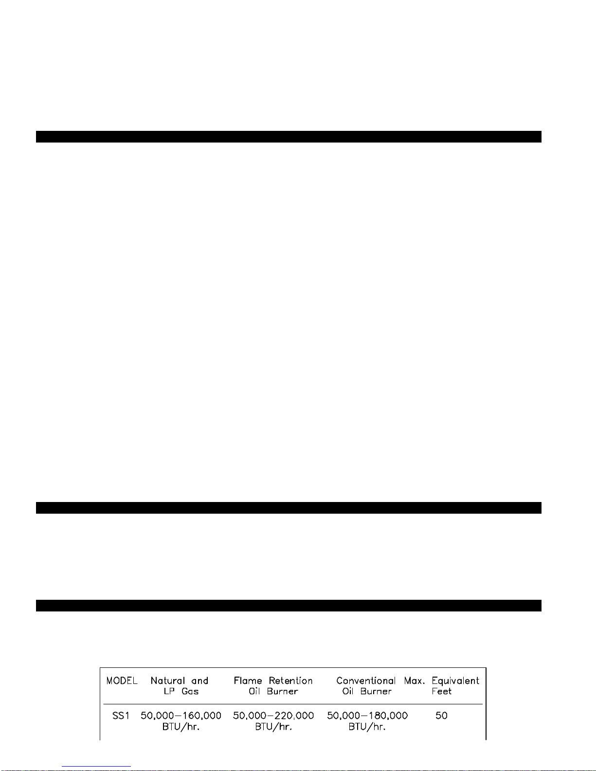
Verify that the total BTU/hr. input of the heating appliance(s) fall within the proper category listed below. All BTU/hr. capacity
ranges are based on a maximum of 50 equivalent feet. To determine equivalent feet, add the total length of straight vent pipe plus
10 feet for each 90 degree elbow and 5 feet for each 45 degree elbow. Vent runs of over 15 linear feet should use an approved,
insulated vent connector to prevent problems related to sulfur condensation.
DESCRIPTION
APPLICATION TABLE
1
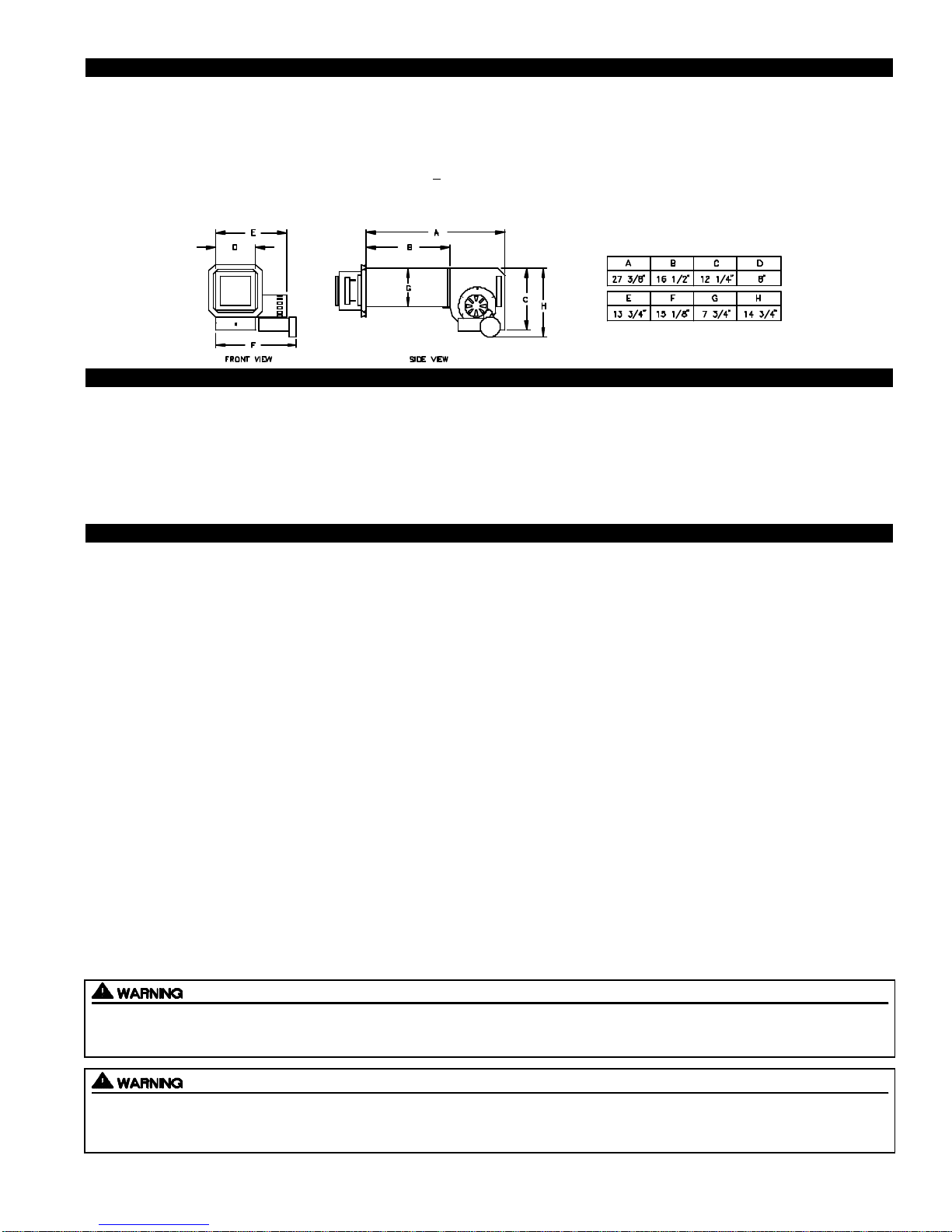
SPECIFICATIONS
Motor: 115/1/60, 3300 RPM, 212 watts, 2.28 FLA
Fan Proving Switch: Non-adjustable set point of -.05" W.C., Contacts rated for an inductive load of 6.2 FLA at 120 VAC.
High Limit: Manual reset N/C contacts, open at 135oF + 10oF, Contacts rated at 10 FLA at 120 VAC.
Post-Purge Timer: Adjustable from 1 to 10 minutes. Dual voltage, non-polarity sensitive input (24-120 VAC).
GENERAL INFORMATION
These units have been factory tested and rated in accordance with AMCA standard 210, Test Code for Air Moving Devices.
Each SideShot is electrically factory line tested before shipment.
After opening carton, inspect thoroughly for hidden damage. Wheel should rotate freely. If any damage is found notify freight car-
rier and your distributor immediately and file a concealed damage claim.
INSTALLATION RESTRICTIONS
1. The SideShot may not be installed on condensing appliances.
2. For Natural Gas, LP Gas and Oil Fired appliances only.
3. The SideShot may not be installed on an appliance with an automatic valve having a manual opener unless the manual
opener has been rendered inoperative or the automatic valve has been replaced with a valve not equipped with a manual
opener.
4. The SideShot may only be installed on appliances equipped with a draft hood, draft diverter or barometric draft control.
5. The SideShot shall not be installed where flue gas temperatures exceed 650oF at its inlet. Flue gas temperature verification:
A) Consult appliance manufacturer for temperature of gases at the appliance after dilution by draft hood, draft diverter or
draft control.
AND
B) Measure temperature of flue gases at the inlet to the SideShot at time of installation. Temperature should be
measured after appliance and SideShot have operated for at least 15 minutes, allowing flue gas temperature to stabilize.
6. The electrical load controlled through the Fan Proving Switch must not exceed its nameplate ratings .
7. Vent runs of over 15 linear feet should use an approved, insulated vent connector to prevent problems related to sulfur condensation.
Improper installation, adjustment, alterations, service or maintenance can cause injury, property damage or death. Refer to this
manual. For assistance or additional information consult a qualified installer, service agency or the equipment supplier.
Do not exceed the recommended input range of the SideShot. Under no circumstances shall the minimum draft adjustment be
used for the larger input range of this product. Improper adjustment may result in the dispersion of flue products (carbon monoxide) into the building interior causing carbon monoxide poisoning or death.
2

CAUTIONS
1. Disconnect power supply from the SideShot and heating equipment when making wiring connections and servicing the
SideShot. Failure to do so may result in personal injury and/or equipment damage.
2. Failure to install, maintain and/or operate the SideShot in accordance with manufacturer's instructions may result in conditions
which can produce bodily injury and property damage.
3. The SideShot must be installed by a qualified installer (an individual properly licensed and/or trained) in accordance with all
local codes or, in their absence, in accordance with the appropriate National Fire Protection Association #31, #54, #211 and the
National Electrical Code.
4. Plan the vent layout so that the code required clearances are maintained from plumbing, wiring and combustible materials.
5. The SideShot motor shaft must be mounted horizontally to ensure proper operation of the Fan Proving Switch and prevent
motor bearing wear.
6. Flue gas temperatures must not exceed 650oF at SideShot inlet. Ambient temperature must not exceed 104oF.
7. Make certain power source is adequate for the SideShot requirements. Do not add the SideShot to a circuit when the total electrical load is unknown.
8. "Safety Inspection of a Previously Used Appliance", pages 3 and 4 must be completed when replacing a conventional chimney
venting system or when SideShot is installed on used heating equipment.
*SAFETY INSPECTION OF A PREVIOUSLY USED OIL APPLIANCE
(Perform prior to SideShot installation)
The following procedure is intended as a guide to aid in determining that an appliance is properly installed and is in safe condition
for continuing use.
This procedure is based on central furnace and boiler installations and it should be recognized that generalized procedures
cannot anticipate all situations. Accordingly, in some cases deviation from this procedure may be necessary to determine safe
operation of the equipment.
a. This procedure should be performed prior to any attempt at modifications of the appliance or installation of the SideShot.
b. If it is determined there is a condition which could result in unsafe operation, the appliance should be shut off and the owner
advised of the unsafe condition.
The following steps should be followed in making the safety inspection:
1. Visually inspect the venting system and determine there is no blockage or restriction, leakage, corrosion or other deficiencies
which could cause an unsafe condition.
2. Inspect burner and primary control for proper operation.
3. Applicable only to furnaces: Inspect heat exchanger for cracks, openings or excessive corrosion. Check both the limit control
and fan control for proper operation.
4. Applicable only to boilers: Inspect for evidence of water or combustion product leaks. Determine that the water pumps are in
operating condition. Test low water cutoffs, automatic feed controls, pressure and temperature limit controls and relief valves in
accordance with the manufacturer's recommendations to determine that they are in operating order.
*SAFETY INSPECTION OF A PREVIOUSLY USED GAS APPLIANCE
(Perform prior to SideShot installation)
The following procedure is intended as a guide to aid in determining that an appliance is properly installed and is in safe condition
for continuing use.
The following procedure is based on central furnace and boiler installations and it should be recognized that generalized procedures cannot anticipate all situations. Accordingly, in some cases deviation from this procedure may be necessary to determine
safe operation of the equipment.
a. This procedure should be performed prior to any attempt at modifications of the appliance or installation of the SideShot.
b. If it is determined there is a condition which could result in unsafe operation, the appliance should be shut off and the owner
advised of the unsafe condition.
3
The following steps should be followed in making the safety inspection:
1. Conduct a gas leakage test of the appliance piping and control system downstream of the shutoff valve in the supply line to the
appliance.
2. Visually inspect the venting system and determine there is no blockage or restriction, leakage, corrosion and other deficiencies
which could cause an unsafe condition.
3. Shut off all gas to the appliance(s).
4. Inspect burners and crossovers for blockage and corrosion.
5. Applicable only to furnaces: Inspect heat exchanger for cracks, openings or excessive corrosion. Check both the limit control
and fan control for proper operation.
6. Applicable only to boilers: Inspect for evidence of water or combustion product leaks. Determine that the water pumps are in
operating condition. Test low water cutoffs, automatic feed controls, pressure and temperature limit controls and relief valves in
accordance with the manufacturer's recommendations to determine that they are in operating order.
* Excerpts from the National Fuel Gas Code (ANSI Z223.1/NFPA #54), Appendix H.
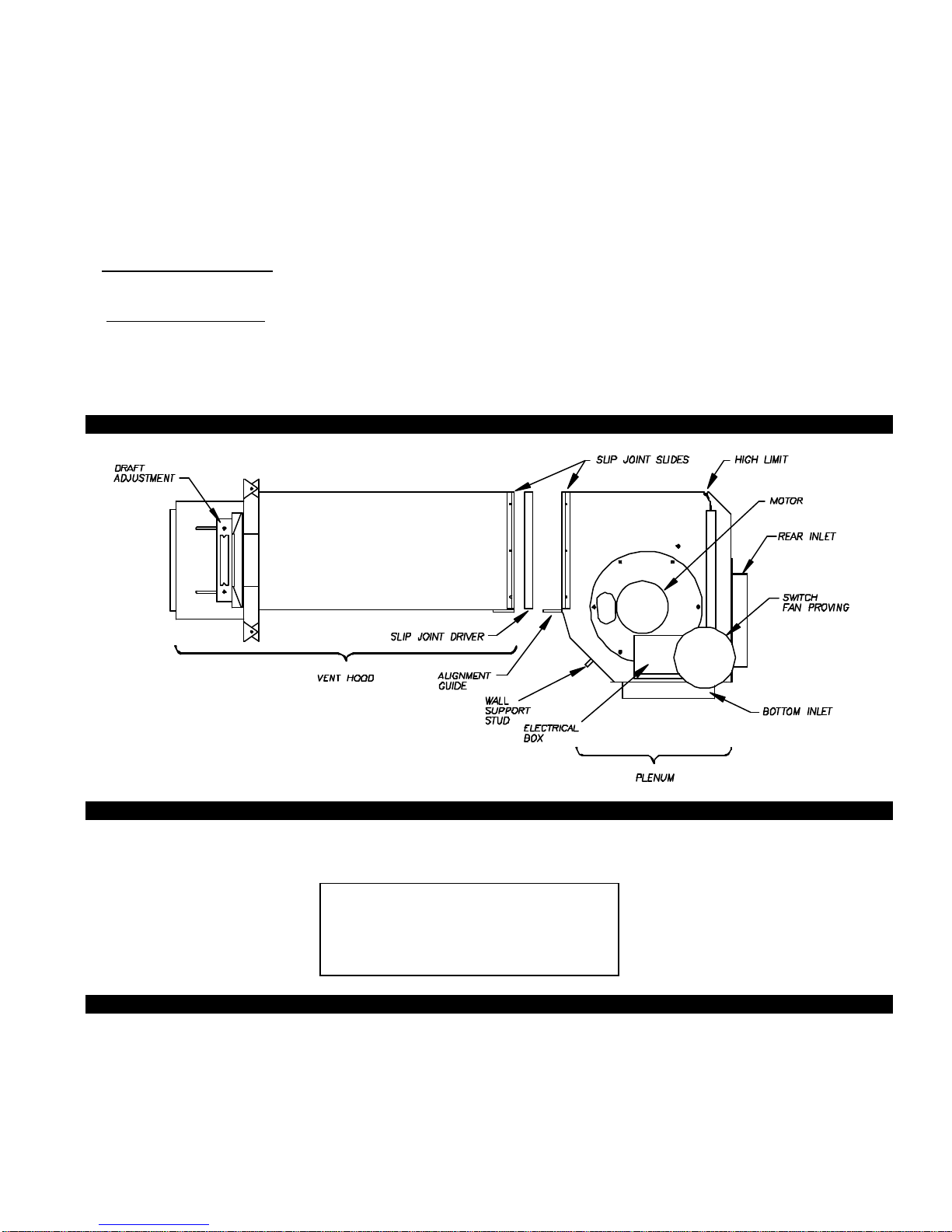
SIDESHOT TERMINOLOGY
PLENUM AND VENT HOOD CLEARANCE FROM COMBUSTIBLES
With an inlet flue gas temperature of 650oF or below, the SideShot has been Listed for the following clearances from combustible
materials:
The SideShot has been ETL Listed according to the requirements of the National Fire Protection Association #31, #54 and #211
as follows, (See Diagram A, Page 5):
• The exit terminals of mechanical draft systems shall not be less than 7 feet above grade when located adjacent to public walk
ways.
• A venting system shall terminate at least 3 feet above any forced air inlet located within 10 feet.
IMPORTANT
Vent Hood and top of Plenum: Zero Clearance
Plenum front and sides: 1/2 inch
Plenum rear: 3 inches
VENT HOOD TERMINATION CLEARANCES
4
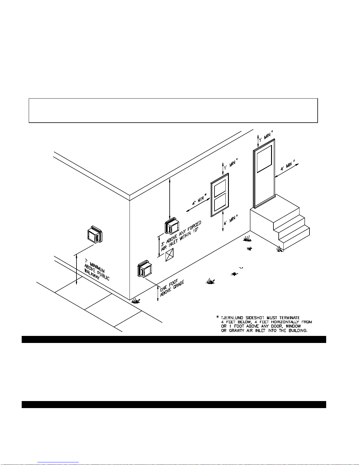
• The venting system shall terminate at least 4 feet below, 4 feet horizontally from or 1 foot above any door, window or gravity air
inlet into any building.
• The bottom of the vent terminal shall be located at least 12 inches above grade.
• The exit terminal shall be so arranged that the flue gases are not directed so as to jeopardize people, overheat combustible
structures or enter buildings.
• Not to be less than 10 feet from an adjacent building.
The SideShot is also Listed to terminate a minimum of 12” below, above or horizontally from a soffit, deck or adjacent sidewall.
It is not recommended for the SideShot to be terminated on a wall that faces the direction of the prevailing winds.
Backdrafts by severe winds can cause oil odors to remain in the structure and/or interrupt heating equipment operation.
DIAGRAM A
INSTALLATION
Tools required:
• Reciprocating Saw • 1/2", 7/16",5/8" Wrench
• Drill and 1/8", 1/4", 1/2" Bits • 1/4" Masonry Drill Bit
• Blade Screwdriver • 1/4", 5/16”, 11/32" Nut Runner or Socket
• Wire Cutter/Stripper • Hammer
• Tube Cutter
1. a) Fold template A (Page 24) along dashed line and attach in between the floor joists ensuring that it is snug against the sill
plate and right hand floor joist. Follow same procedure if floor trusses are used, (See Diagram B).
b) If the SideShot is not being installed between floor joists, attach the template to the wall it will be exiting ensuring it is level.
INSTALLING VENT HOOD TERMINUS
5
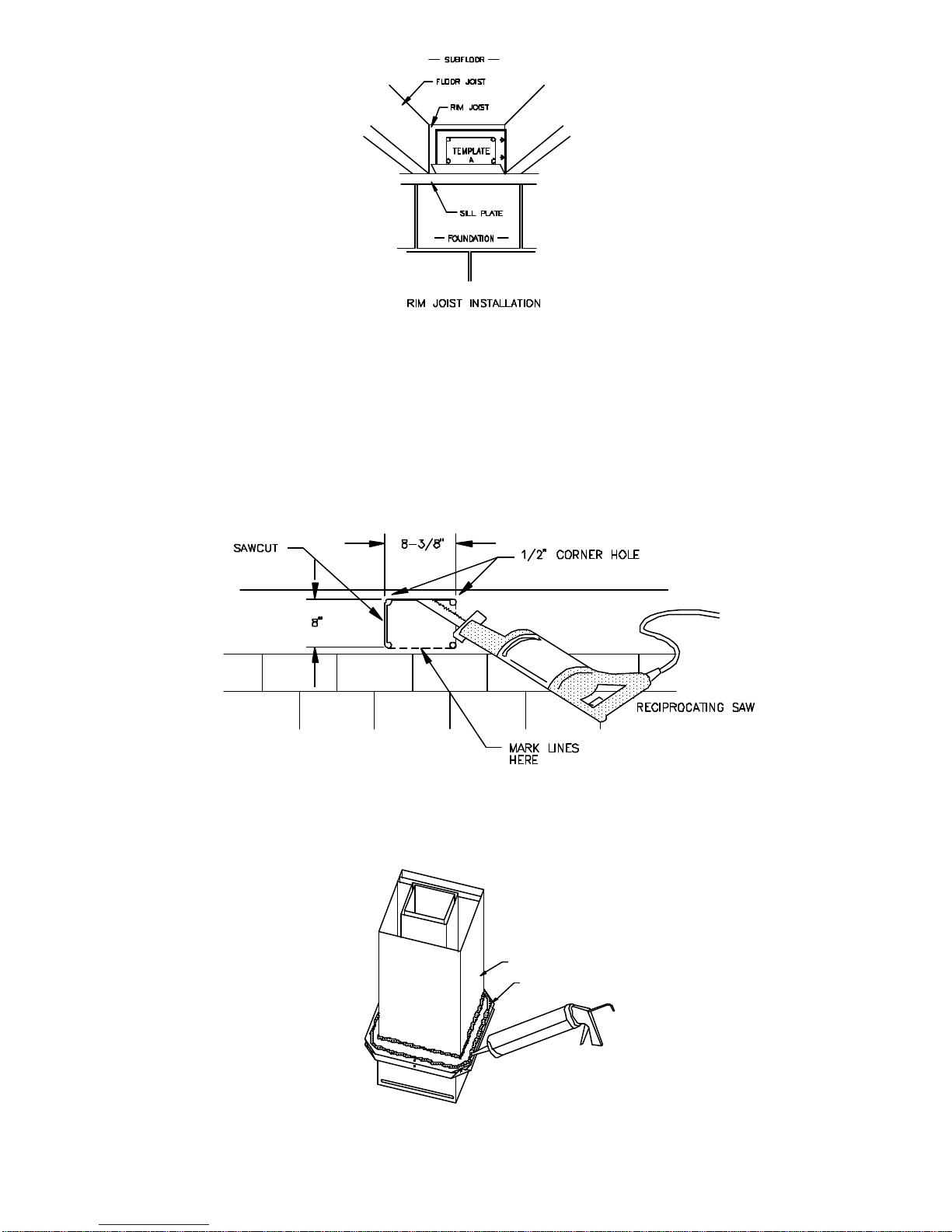
DIAGRAM B
2. Using 1/2" bit, drill pilot holes noted on each side of the template from inside through rim-joist, wall board, siding, etc., keeping
drill bit perpendicular to the wall. 1/2" bit must be long enough to penetrate through exterior.
3. Remove template from rim-joist and attach to building exterior, aligning pilot hole markings on template with holes previously
created in Step #2.
4. Drill the four corner holes noted on the template through the building exterior. Remove the template and mark lines from the
outside edge of the holes drilled, forming a rectangle.
5. Using reciprocating saw and appropriate blade, cut a rectangular opening through the rim joist, wall board, siding, etc., on the
lines marked in step 4. The rectangular opening should be no larger than 8-3/8" in width by 8" in height, (See Diagram C).
DIAGRAM C
6. Knock out block material exposing rectangular opening through the wall.
7. Apply two beads of exterior rated caulk approximately 3/8" in width at the seam of the outermost casing of the Vent Hood and
the inner flange of the Vent Hood Terminus, (See Diagram D).
OUTERMOST CASING
INNER FLANGE OF VENT
DIAGRAM D
HOOD TERMINUS
6
 Loading...