

TJERNLUND SS1R SIDESHOT (DISCONTINUED VERSION-PRE UC1 UNIVERSAL CONTROL) 8504046 REV 0595 Installation Instructions Manual
REV. 5/95
TJERNLUND PRODUCTS, INC.
1601 Ninth Street • White Bear Lake, MN 55110-6794
PHONE (800) 255-4208 • (651) 426-2993 • FAX (651) 426-9547
Visit our web site • www.tjernlund.com
THIS VENT SYSTEM HAS BEEN LISTED FOR USE WITH SPECIFIED
RHEEM, RUUD, WEATHERKING AND HEAT CONTROLLER OIL
FURNACES BY UL AND ULC. SEE FURNACE RATING PLATE FOR
VERIFICATION.
MODEL SS1-R
INSTALLATION INSTRUCTIONS
Recognize this symbol as an indication of important Safety Information!
!
OWNER INSTRUCTIONS, DO NOT DESTROY
NOTE: FLUE GAS TEMPERATURES MUST NOT EXCEED
575oFAT VENT SYSTEM INLET.
THESE INSTRUCTIONS ARE INTENDED AS AN AID TO QUALIFIED, LICENSED
SERVICE PERSONNEL FOR PROPER INSTALLATION, ADJUSTMENT AND
OPERATION OF THIS UNIT. READ THESE INSTRUCTIONS THOROUGHLY
BEFORE ATTEMPTING INSTALLATION OR OPERATION. FAILURE TO FOLLOW
THESE INSTRUCTIONS MAY RESULT IN IMPROPER INSTALLATION, ADJUSTMENT, SERVICE OR MAINTENANCE POSSIBLY RESULTING IN FIRE, ELECTRICAL SHOCK, CARBON MONOXIDE POISONING, EXPLOSION, OR PERSONAL
INJURY OR PROPERTY DAMAGE.
DO NOT DESTROY. PLEASE READ CAREFULLY AND
KEEP IN A SAFE PLACE FOR FUTURE REFERENCE.
Copyright © 1995, Tjernlund Products, Inc. All rights reserved P/N 8504046
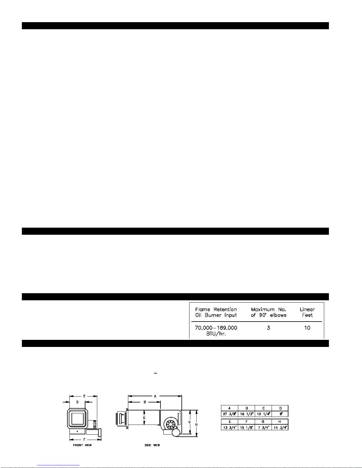
TABLE OF CONTENTS
Page (s)
Description and Specifications ........................................................................................................................................1
Installation Restrictions .................................................................................................................................................2
Cautions .........................................................................................................................................................................2
Safety Inspection of a Previously Used Appliance .........................................................................................................3
SS1-R Terminology ........................................................................................................................................................3
Vent Hood Termination Clearances For U.S. Installations..............................................................................................4
Vent Hood Termination Clearances For Canadian Installations......................................................................................5
Installation
Tools Required .................................................................................................................................................6
Vent Hood Installation ..................................................................................................................................6, 7
Installation of Rain Shield .................................................................................................................................7
Plenum Installation ...................................................................................................................................7, 8, 9
Installation of Vent Pipe ..............................................................................................................................9, 10
Electrical Wiring
Wiring Restrictions ..........................................................................................................................................11
Installation of Oil Solenoid Valve.....................................................................................................................11
Field Wiring Connections ................................................................................................................................12
Installation of R1 Relay and Junction Box Extension......................................................................................13
Selection of Proper Bleed Orifice & Draft Adjustment ............................................................................................13, 14
Combustion Air .............................................................................................................................................................14
System Operation Check Out .......................................................................................................................................15
Trouble Shooting Oil Odors...........................................................................................................................................15
Trouble Shooting Electrical Problems .....................................................................................................................16, 17
Maintenance..................................................................................................................................................................18
Removal & Replacement of Motor/Wheel ......................................................................................................18
Warranty ........................................................................................................................................................................19
Mounting Templates
Template B Motor Notch ................................................................................................................................20
Template A Vent Hood Terminus ....................................................................................................................21
SideShot®is a registered trademark of Tjernlund Products, Inc. for their Model SS1-R Vent System.
DESCRIPTION
The SS1-R is a mechanical vent system designed and listed for use with specified Rheem, Ruud, Weatherking and Heat
Controller oil fired furnaces. The SS1-R automatically vents the flue gases away from the oil furnace to the outdoors. By combining outside air with high-tech insulation and maintaining required clearances, surrounding combustible materials remain at safe
temperatures. After each burner cycle, the SS1-R and the burner motor will continue operating for an adjustable post-purge
period. The post-purge provides numerous system benefits, therefore, it is not recommended to reduce the post-purge time from
that which is set at the factory. The SS1-R also features a two way safety system consisting of a fan proving switch and a high
limit control. These devices monitor the SS1-R’s performance and will interrupt furnace operation if a malfunction is detected.
APPLICATION TABLE
Verify that the total BTU/hr. input of the heating appliance(s) fall
within the proper category listed below. All BTU/hr. capacity ranges
are based on a maximum of 10 linear feet of vent pipe with no more
than 3 - 900elbows. (Two 450elbows are equivalent to one 900elbow)
SPECIFICATIONS
Motor: 115/1/60, 3300 RPM, 212 watts, 2.28 FLA
Fan Proving Switch: Non-adjustable set point of -.04" W.C., Contacts rated for an inductive load of 6.2 FLA at 120 VAC.
High Limit: Manual reset N/C contacts, open at 135oF + 10oF, Contacts rated at 10 FLA at 120 VAC.
Post-Purge Timer: Adjustable from 1 to 10 minutes. Dual voltage, non-polarity sensitive input (24-120 VAC).
Relay: (Mounted On junction box extension): SPST, N/O contacts rated at 12 FLA, 60 LRA at 120 VAC
Oil Solenoid Valve: ON - Off control of oil flow to burner; 3-8 second valve opening delay; 120 VAC, .115 Amps, 13.8 VA
1
GENERAL INFORMATION
These units have been factory tested and rated in accordance with AMCA standard 210, Test Code for Air Moving Devices and
also rated in accordance with the following Canadian Standards: CAN/CSA - B140.0-M87 General Requirements For Oil Burning
Equipment; CAN/CSA - B139-M91 Installation Code For Oil Burning Equipment; CAN3 - B255-M81 Mechanical Flue - Gas Exhausters.
Each SS1-R is electrically factory line tested before shipment.
After opening carton, inspect thoroughly for hidden damage. Wheel should rotate freely. If any damage is found notify freight car-
rier and your distributor immediately and file a concealed damage claim.
INSTALLATION RESTRICTIONS
1. Do not install on condensing appliances. Use this device only on specified oil fired Rheem, Ruud, Weatherking & Heat
Controller furnaces. Do not use with more than one furnace.
2. A barometric draft control must be used with the SS1-R.
3. Do not use single wall vent pipe in unconditioned or unheated spaces.
4. The SS1-R shall not be installed where flue gas temperatures exceed 575oF at its inlet. Flue gas temperature verification:
Measure temperature of flue gases at the inlet to the SS1-R at time of installation. Measure the temperature after the appliance
and SS1-R operate for at least 15 minutes, allowing flue gas temperature to stabilize.
Improper installation, adjustment, alterations, service or maintenance can cause injury, property damage or death. Refer to this
manual. For assistance or additional information consult a qualified installer, service agency or the equipment supplier.
Do not exceed the recommended input range of the SS1-R. Under no circumstances shall the minimum draft adjustment be used
for the larger input range of this product. Improper adjustment may result in the dispersion of flue products (carbon monoxide)
into the building interior causing carbon monoxide poisoning or death.
CAUTIONS
Disconnect power supply from the oil furnace when making wiring connections and servicing the SS1-R. Failure to do so may
result in personal injury and/or equipment damage.
1. The SS1-R must be installed by a qualified installer (an individual properly licensed and/or trained) in accordance with all local
codes. In the absence of local codes, USA installations should be in accordance with the latest editions of the applicable
National Fire Protection Agency (NFPA) code. These are NFPA 31 (Installation of Oil-Burning Equipment), and NFPA 211
(Chimneys, Fireplaces, Vents and Solid Fuel burning Appliances). In addition, USA installations must comply with the National
Electrical Code. In the absence of local codes in Canada, installations must comply with CSA Std 139 (The National Building
Code of Canada) and CSA Std 22.1 (The Canadian Electrical Code).
2. Plan the vent layout so that the code required clearances are maintained from plumbing, wiring and combustible materials.
3. The SS1-R motor shaft must be mounted horizontally to ensure proper operation of the Fan Proving Switch and prevent
motor bearing wear.
4. Flue gas temperatures must not exceed 575oF at SS1-R inlet. Ambient temperature must not exceed 104oF.
5. Make certain the power source is adequate for the SS1-R requirements. Do not add the SS1-R to a circuit where the
total electrical load is unknown.
6. "Safety Inspection of a Previously installed Appliance" must be completed when replacing a conventional chimney
venting system or when SS1-R is installed on Rheem, Ruud, Weatherking or Heat Controller oil fired furnaces.
7. The SS1-R vent system, including vent pipe, must be inspected annually by a qualified individual.
2
*SAFETY INSPECTION OF A PREVIOUSLY INSTALLED OIL APPLIANCE
(Perform prior to SS1-R installation)
The following procedure is intended as a guide to aid in determining that an appliance is properly installed and is in safe condition
for continuing use.
This procedure is based on central furnace installations and it should be recognized that generalized procedures cannot anticipate
all situations. Accordingly, in some cases deviation from this procedure may be necessary to determine safe operation of the
equipment.
a. Install the SS1-R only on specified Rheem, Ruud, Weatherking & Heat Controller oil fired furnaces.
b. Complete this procedure prior to any attempt at modifications of the appliance or installation of the SS1-R.
c. If there is a condition which could result in unsafe operation, shut off the appliance and advise the owner
of the unsafe condition.
The following steps should be followed in making the safety inspection:
1. Visually inspect the venting system and determine there is no blockage or restriction, leakage, corrosion or other deficiencies
which could cause an unsafe condition.
2. Inspect burner and primary control for proper operation.
3. Inspect heat exchanger for cracks, openings or excessive corrosion. Check both the limit control and fan control for proper
operation.
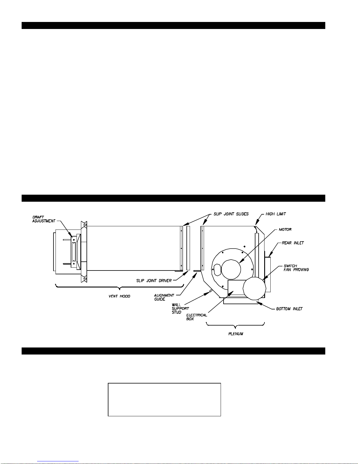
SS1-R TERMINOLOGY
PLENUM AND VENT HOOD CLEARANCE FROM COMBUSTIBLES
With an inlet flue gas temperature of 575oF or below, the SS1-R has been Listed for the following clearances from combustible
materials:
Vent Hood and top of Plenum: Zero Clearance
Plenum front and sides: 1/2 inch
Plenum rear: 3 inches
IMPORTANT
3
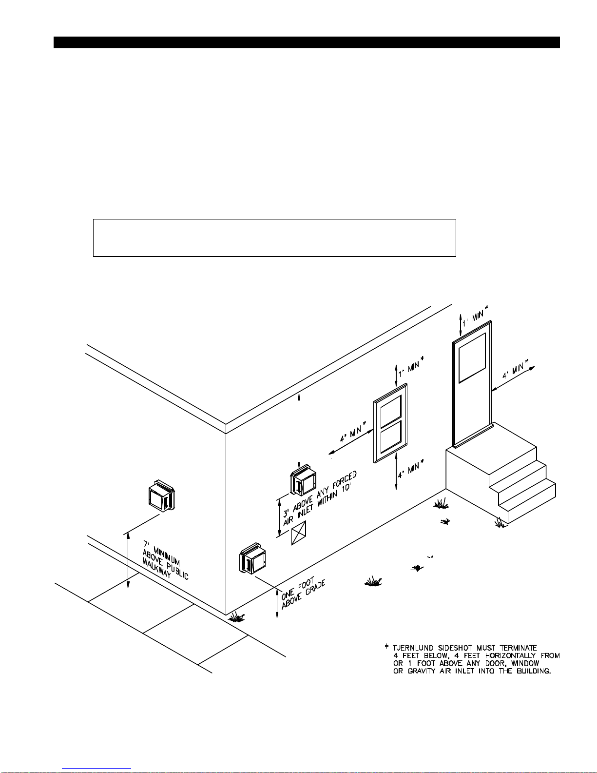
VENT HOOD TERMINATION CLEARANCES FOR U.S. INSTALLATIONS
Install the SS1-R according to the requirements of the National Fire Protection Association #31, #54 and #211 as follows,
(See Diagram A):
• The exit terminals of mechanical draft systems shall not be less than 7 feet above grade when located adjacent to public walk
ways.
• A venting system shall terminate at least 3 feet above any forced air inlet located within 10 feet.
• The venting system shall terminate at least 4 feet below, 4 feet horizontally from or 1 foot above any door, window or gravity air
inlet into any building.
• The bottom of the vent terminal shall be located at least 12 inches above grade.
• Arrange the exit terminal so that the flue gases are not directed so as to jeopardize people, overheat combustible structures or
enter buildings.
• Not to be less than 2 feet from an adjacent building.
The SS1-R is also Listed to terminate a minimum of 12" below, above or horizontally from a soffit, deck or adjacent sidewall.
It is not recommended for the SS1-R to be terminated on a wall that faces the direction of
the prevailing winds. Backdrafts by severe winds can cause oil odors to remain in the
structure and/or interrupt heating equipment operation.
VENT HOOD TERMINAT
DIAGRAM A
4
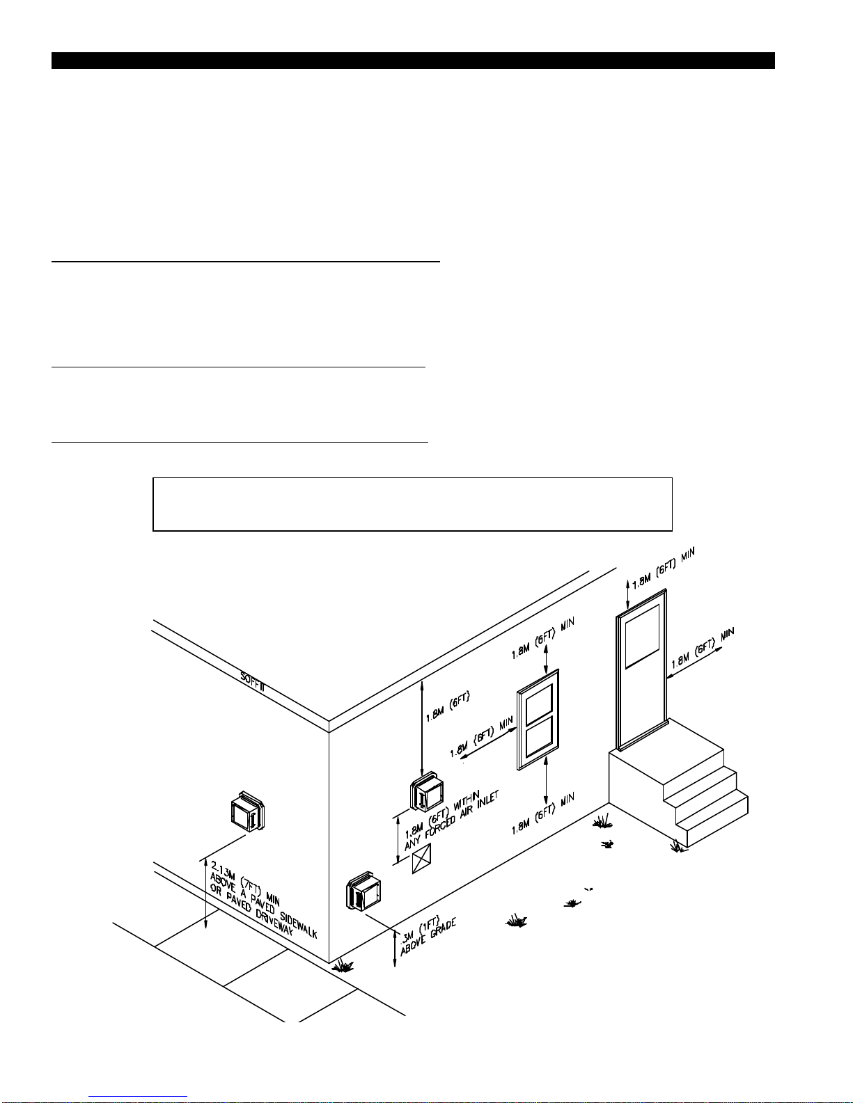
TERMINATION CLEARANCES FOR CANADIAN INSTALLATIONS
The SS1-R has been CSA Listed according to the requirements of “Mechanical Flue-Gas Exhausters” CSA Std B255-M81 and
the “Installation code for Oil burning Equipment” CSA Std B139-M91. (See Diagram. A1)
• A venting system shall not terminate underneath a veranda, porch, or deck, or above a paved sidewalk or a paved driveway
that is located between two buildings, and that serves both buildings.
• The exit terminals of mechanical draft systems shall not be less than 2.13m (7ft) above grade when located adjacent to a paved
sidewalk or driveway.
• A venting system shall not direct flue gases towards brickwork, siding, or other construction, in such a manner that may cause
damage from heat or condensate from the flue gases.
• A venting system shall not direct flue gases so as to jeopardize people, overheat combustible structures, or enter buildings.
A venting system shall not terminate within 1.8 m (6ft) of the following:
• A window, door or mechanical air supply inlet of any building, including soffit openings
• A gas service regulator vent outlet
• A combustion air inlet
• A property line
• A direction facing combustible materials or openings of surrounding buildings
A venting system shall not terminate within 1m (3ft) of the following:
• Above a gas meter/regulator assembly within 1m (3ft) horizontally of the vertical centreline of the regulator
• A oil tank or an oil tankfill inlet
• The inside corner of an L-shaped structure
A venting system shall not terminate within .3m (1ft) of the following:
• Above grade level or any surface that may support snow, ice, or debris
DIAGRAM A1
It is not recommended for the SS1-R to be terminated on a wall that faces the direction of
the prevailing winds. Backdrafts by severe winds can cause oil odors to remain in the
structure and/or interrupt heating equipment operation.
5
 Loading...