

TJERNLUND SS1C SIDESHOT WITH UC1 UNIVERSAL CONTROL (VERSION X.04) 8504103 REV C 0204, SIDESHOT SS1C Installation Instructions Manual
Copyright © 2004, Tjernlund Products, Inc. All rights reserved P/N 8504103
OWNER INSTRUCTIONS, DO NOT DESTROY
Recognize this symbol as an indication of important Safety Information!
NOTE: FLUE GAS TEMPERATURES MUST NOT EXCEED
301oC (575oF) AT VENT SYSTEM INLET.
THESE INSTRUCTIONS ARE INTENDED AS AN AID TO QUALIFIED, LICENSED
SERVICE PERSONNEL FOR PROPER INSTALLATION, ADJUSTMENT AND
OPERATION OF THIS UNIT. READ THESE INSTRUCTIONS THOROUGHLY
BEFORE ATTEMPTING INSTALLATION OR OPERATION. FAILURE TO FOLLOW
THESE INSTRUCTIONS MAY RESULT IN IMPROPER INSTALLATION, ADJUSTMENT, SERVICE OR MAINTENANCE POSSIBLY RESULTING IN FIRE, ELECTRICAL SHOCK, CARBON MONOXIDE POISONING, EXPLOSION, OR PERSONAL
INJURY OR PROPERTY DAMAGE.
!
DO NOT DESTROY. PLEASE READ CAREFULLY AND
KEEP IN A SAFE PLACE FOR FUTURE REFERENCE.
MODEL SS1C
INSTALLATION INSTRUCTIONS
REV. C 02/04
TJERNLUND PRODUCTS, INC.
1601 Ninth Street • White Bear Lake, MN 55110-6794
PHONE (800) 255-4208 • (651) 426-2993 • FAX (651) 426-9547
Visit our web site • www.tjernlund.com
INCLUDES NEW UC1
UNIVERSAL CONTROL
VERSION
X.04

1
Tjernlund Products welcomes your comments and questions. Address all correspondence to:
Customer Service • Tjernlund Products, Inc. • 1601 Ninth Street • White Bear Lake, MN 55110-6794
Call us toll free at 800-255-4208, visit our web site @ www.tjernlund.com or email us at fanmail@tjfans.com.
TABLE OF CONTENTS
Page (s)
Description and Specifications ....................................................................................................................................1, 2
Installation Restrictions .............................................................................................................................................2, 3
Cautions .........................................................................................................................................................................3
Safety Inspection of a Previously Used Appliance .........................................................................................................3
SideShot Model SS1C Terminology ...............................................................................................................................3
SideShot
®
With Integral UC1 Universal Control Board Features ...................................................................................4
LED Status / Fault Indicators and Fault Retrieval from Memory .................................................................................4, 5
Pre / Post-Purge & Pre-Cycle Prover Status Check Settings......................................................................................5, 6
Termination Clearances .................................................................................................................................................6
Installation
Tools Required .................................................................................................................................................7
Vent Hood Installation ..............................................................................................................................7, 8, 9
Installation of Rain Shield .................................................................................................................................8
Plenum Installation .................................................................................................................................8, 9, 10
Installation of Vent Pipe ............................................................................................................................10, 11
Electrical Wiring
Warnings, Sequence of Operation & Internal Schematic ...............................................................................12
Wiring to Oil Fired Equipment ......................................................................................................13, 14, 15, 16
Fan Proving Switch Bleed Orifice Selection ..................................................................................................................16
Draft Adjustment Procedure (Oil) ............................................................................................................................17, 18
Combustion Air ............................................................................................................................................................. 18
System Operation Check Out .......................................................................................................................................18
Troubleshooting Oil Odors.......................................................................................................................................18, 19
Troubleshooting Electrical Problems .................................................................................................................19, 20, 21
Maintenance ............................................................................................................................................................21, 22
Removal & Replacement of Motor/Wheel ................................................................................................21, 22
Warranty & Replacement Parts ...............................................................................................................................22, 23
Mounting Templates
Template B Motor Notch ................................................................................................................................24
Template A Vent Hood Terminus....................................................................................................................25
SideShot
®
is a registered trademark of Tjernlund Products, Inc. for their Models SS1 & SS2 Vent Systems.
DESCRIPTION
The SS1C is a mechanical vent system designed and listed for use with natural draft oil heating equipment. It is factory assembled and wired. The SS1C automatically vents the flue gases from heating equipment to the outdoors. By combining outside air
with high-tech insulation, surrounding combustible materials and the Vent Hood exterior remain at safe temperatures. After each
burner cycle the SS1C will continue to operate in post-purge mode to purge the heater and vent of residual flue gases. A factory
post-purge time is set at 2 minutes and is adjustable up 16 minutes, see “Pre / Post-purge Settings” on page 5. The SS1C features a safety system consisting of the integral UC1 Universal Control, a Fan Proving Switch and a High Limit temperature control.
These devices monitor the SS1C’s performance and will interrupt the main burner if a venting malfunction is detected.
APPLICATION TABLE
Verify that the total BTU/hr. input of the heating appliance(s) fall within the proper category listed below. All BTU/hr. capacity
ranges are based on a maximum of 15.2 equivalent meters (50 feet). To determine equivalent meters, add the total length of
straight vent pipe plus 3.1 meters (10 feet) for each 90 degree elbow and 1.5 meters (5 feet) for each 45 degree elbow. Vent
runs of over 4.5 linear meters (15 linear feet) should use an approved, insulated vent connector to prevent problems related to
sulfur condensation.
2
SPECIFICATIONS
Motor: 115/1/60, 3300 RPM, 212 watts, 2.28 FLA
Fan Proving Switch: Non-adjustable, N/O with a set point of -.04" W.C.
High Limit: Manual reset, N/C contacts, open at 79oC (175oF) +
8oC (15oF)
UC1 Universal Control: See UC1 Universal Control Board Features on page 4.
Pre-Purge: Options (0, 5, 20, 35 seconds); Post-Purge: Factory set at 2 minutes, Options (0, 30 seconds or 1, 2, 4, 8, 16 minutes).
See Page 5 for Pre / Post-purge options.
GENERAL INFORMATION
These units have been factory tested and rated in accordance with the following Canadian Standards: CAN/CSA - B140.0-M87
General Requirements For Oil Burning Equipment; CAN/CSA - B139-M91 Installation Code For Oil Burning Equipment;
CAN3 - B255-M81 Mechanical Flue - Gas Exhausters.
Each SideShot is electrically factory line tested before shipment.
After opening carton, inspect thoroughly for hidden damage. Wheel should rotate freely. If any damage is found notify freight carrier and your distributor immediately and file a concealed damage claim.
INSTALLATION RESTRICTIONS
1. The SideShot may not be installed on condensing appliances, incinerators, incinerating toilets or solid fuel burning appliances.
2. The SideShot Model SS1C is Listed for Oil Fired appliances only.
3. The SideShot may only be installed on appliances equipped with a barometric draft control.
4. The SideShot shall not be installed where flue gas temperatures exceed 301oC (575oF) at its inlet. Flue gas temperature
verification:
A) On oil fuel, verify flue gas temperature at SS1C inlet is at or above 250oF (121oC) after 5 minutes of operation during
setup. See “Oil Draft Adjustment Procedure” on page 18, step 10.
AND
B) Measure temperature of flue gases at the inlet to the SideShot at time of installation. Temperature should be
measured after appliance and SideShot have operated for at least 15 minutes, allowing flue gas temperature to stabilize.
5. The maximum recommended wall thickness is 39cm (15”).
6. Vent runs of over 4.5 linear meters (15 linear feet) should use an approved, insulated vent connector to prevent problems
related to sulfur condensation.
CAUTIONS
Improper installation, adjustment, alterations, service or maintenance can cause injury, property damage or death. Refer to this
manual. For assistance or additional information consult a qualified installer, service agency or the equipment supplier.
Do not exceed the recommended input range of the SideShot. Under no circumstances shall the minimum draft adjustment be
used for the larger input range of this product. Improper adjustment may result in the dispersion of flue products (carbon monoxide) into the building interior causing carbon monoxide poisoning or death.
If oil nozzle is changed or other equipment is added perform “Draft Adjustment Procedure” on pages 17, 18 again.
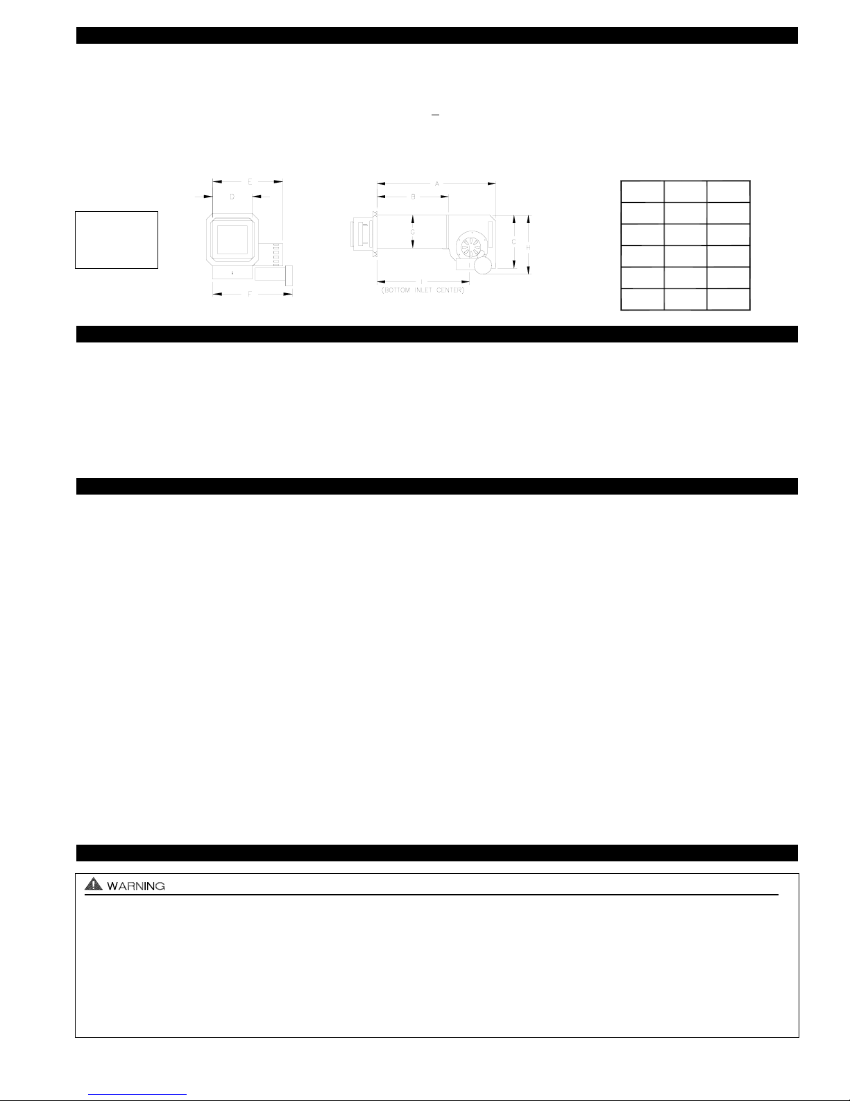
12 1/4"16 1/2"27 3/8"
ABC
15 1/8"
8"
D
13 3/4"
EF
7 3/4"G14 3/4"H23 1/4"
I
Rough-In
8” Height
8 3/8” Width
FRONT VIEW
SIDE VIEW
The SS1C must be installed by a qualified installer (an individual properly licensed and/or trained) in accordance with all
local codes or, in their absence, in accordance with “The National Building Code of Canada” CSA Std B139 & “The Canadian
Electrical Code” CSA Std C22.1.
Failure to install, maintain and/or operate the SS1C in accordance with manufacturer's instructions may result in conditions
which can produce bodily injury and property damage.
1. The installer must verify that the BTU/hr. input of the appliance does not exceed the recommended input of the SS1C. See
“Application Table” on page 1 of these instructions for maximum input capacities.
2. Disconnect power supply from the SS1C and heating equipment when making wiring connections and servicing the SS1C.
Failure to do so may result in personal injury and/or equipment damage. LED #5 (RED) should be off with power removed.
3. Plan the vent layout so that the code required clearances are maintained from plumbing, wiring and combustible materials.
4. The SS1C motor shaft must be mounted horizontally to ensure proper operation of the Fan Proving Switch and prevent
motor bearing wear.
5. Flue gas temperatures must not exceed 301oC (575oF) at SS1C inlet. Ambient temperature must not exceed 40oC (104oF).
6. Oil fuel, flue gas temperature at vent system inlet must be at least 121oC (250oF) during appliance steady state.
7. Make certain power source is adequate for the SS1C requirements. Do not add the SS1C to a circuit when the total
electrical load is unknown.
8. "Safety Inspection of a Previously Used Appliance", below must be completed when replacing a conventional chimney venting
system or when SideShot is installed on used heating equipment.
SAFETY INSPECTION OF A PREVIOUSLY USED APPLIANCE
(Perform prior to SideShot installation)
The following procedure is intended as a guide to aid in determining that an appliance is properly installed and is in safe condition
for continuing use. This procedure is based on central furnace and boiler installations and it should be recognized that generalized procedures cannot anticipate all situations. Accordingly, in some cases deviation from this procedure may be necessary to
determine safe operation of the equipment.
a. This procedure should be performed prior to any attempt at modifications of the appliance or installation of the SS1C.
b. If it is determined there is a condition which could result in an unsafe operation, the appliance should be shut off and the owner
advised of the unsafe condition.
The following steps should be followed in making the safety inspection:
1. Visually inspect the venting system and determine there is no blockage or restriction, leakage, corrosion or other deficiencies
which could cause an unsafe condition.
2. Inspect burner and primary control for proper operation.
3. Applicable only to furnaces:
Inspect heat exchanger for cracks, openings or excessive corrosion. Check both the limit control
and fan control for proper operation.
4. Applicable only to boilers:
Inspect for evidence of water or combustion product leaks. Determine that the water pumps are in
operating condition. Test low water cutoffs, automatic feed controls, pressure and temperature limit controls and relief valves in
accordance with the manufacturer's recommendations to determine that they are in operating order.
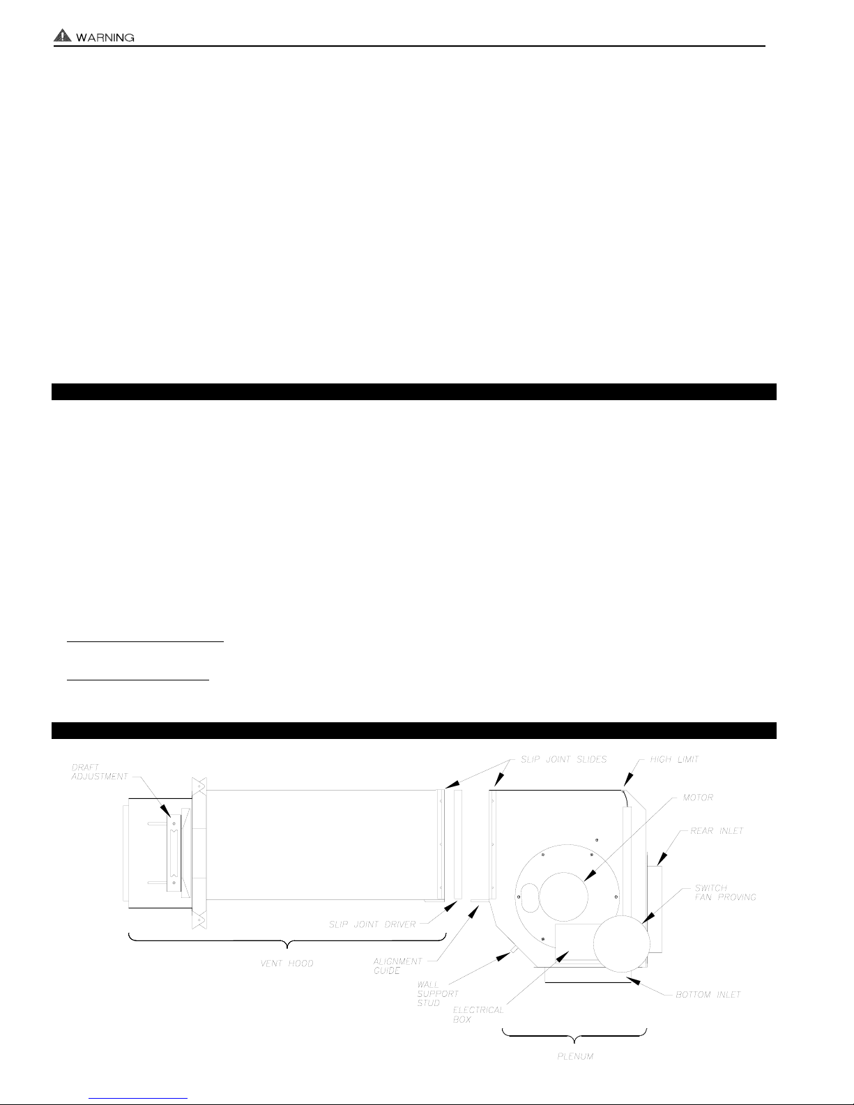
SIDESHOT®MODEL SS1C TERMINOLOGY
3
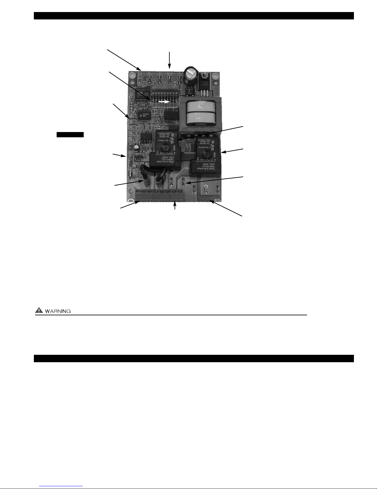
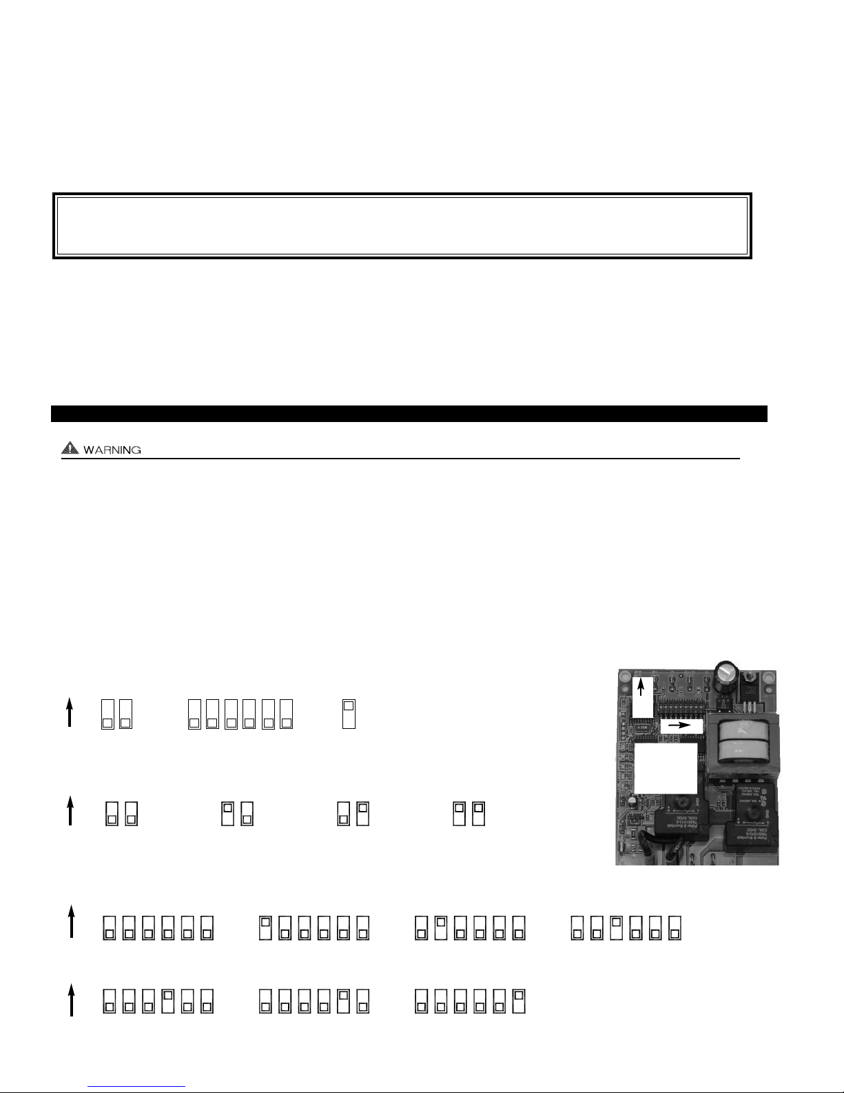
SS1C WITH INTEGRAL UC1 UNIVERSAL CONTROL BOARD FEATURES
# 1. Power supplied by board. Do not supply power to this area or control damage may result.
# 2. Do not supply power to the appliance interlock block with the call selector in the “DRY” position.
Control damage may result if power is supplied.
# 3. Circuit protection must be provided by the installer. 16 Amps is the maximum current allowed for this device at terminal L.
VETI
I
A 15 Amp circuit breaker is recommended.
A
LED STATUS & FAULT INDICATORS
LED INDICATOR LIGHTS
LED #1 (Amber) Appliance call for heat.
LED #2 (Green) Safety circuit through P1 & P2 (SS1C Limit & Fan Prover) is verified “Open” upon start-up. Indicates Venter
prover is closed during run cycle. Burner circuit is energized with contact closure from terminal 3 to 4.
LED #3 (Green) Power switched to SS1C motor from L to MTR & M.
LED #4 (Red) Status / Fault indicator.
LED #5 (Red) 115 VAC power supplied to board. Also used as a status indicator.
LED STATUS INDICATORS
LED #4 & #5 (Red) Flashing Alternately = Venter in Pre-purge. (Pre-Purge options 0, 5, 20, 35 seconds)
LED #4 & #5 (Red) Flashing in Unison = Venter in Post-Purge. (Post-Purge options 0, 30 seconds or 1, 2, 4, 8, 16 minutes)
LED #4 Flashes Continuously* = Fan Prover opened for more than 10 seconds during burner cycle.
(Venter will run for 10 minutes, attempting to make Fan Prover)
4
APPLIANCE CALL
VOLTAGE SELECTION
Place RED voltage jumper in
proper location based on
appliance call interlock voltage. SEE WARNING # 2.
IMPORTANT
LED 1 (AMBER)
LED 2 (GREEN)
LED 3 (GREEN)
LED 4 (RED)
LED 5 (RED)
DRY
24 V
115 V
APPLIANCE
INTERLOCK
RELAY
VENTER
MOTOR
RELAY
A B 1 2 3 4 L N
J1 J2 XL XN
P1 P2 C GND F
(1 9)
N M MTR
J1- J2 CALL
JUMPER
Used when the call signal is
used as the “proven” return
signal to the appliance. See
wiring section for details.
L / N - 115 VAC POWER
SUPPLY BLOCK
115 VAC / 50-60 Hz
Circuit protection provided by installer.
SEE WARNING # 3.
MTR & M / N LOAD TERMINALS
FROM VENTER MOTOR RELAY
Used to drive Venter Motor.
1 HP MAX LOAD across terminals MTR & M / N.
XL / XN AUXILIARY DEVICE
POWER TERMINALS
115 VAC - Maximum of 0.15 Amps.
Only connect to Tjernlund auxiliary devices.
SEE WARNING # 1.
APPLIANCE INTERLOCK
RELAY
1 HP MAX LOAD across
terminals 3 & 4.
P1 - P2 SAFETY CIRCUIT
TERMINALS
1 mA @ 5VDC.
SEE WARNING # 1.
C, GND, F AUXILIARY DEVICE
COMMUNICATION TERMINALS
2 mA @ 5VDC. For Tjernlund MAC1E or
MAC4E auxiliary devices. SEE WARNING # 1.
DIP SWITCH SETTINGS
Pre-Purge (1-2)
Post-Purge (3-8)
Prover status check (9)
See “Pre / Post Purge &
Prover Status Check Dip
Switch Settings”.
LED STATUS LIGHTS
See “LED Status & Fault
Indicator Section” for details.
APPLIANCE INTERLOCK
TERMINAL BLOCK (A-B, 1-4)
A - B - Dry Contact call. 3 mA @ 5VDC.
SEE WARNING # 1.
1 - 24 or 115 VAC intercepted call.
IMPORTANT: RED voltage jumper must
match intercepted call voltage.
2 - 24V common or 115V Neutral.
3 - Common terminal to appliance relay con-
tacts. IMPORTANT: J1-J2 jumper routes
call voltage at terminal 1 to 3. Remove
J1-J2 jumper if a different voltage source is
provided to terminal 3.
4 - Normally open terminal of appliance relay.
Will be energized from terminal 3 if safety
circuit is “proven”.
VENTER MOTOR RELAY
1 HP MAX LOAD from
terminals L to MTR & M.
LED FAULT INDICATORS
Fault conditions are indicated by counting the number of times LED #4 (Red) flashes.
LED #4 Flashes 2 Times Fan Prover was in electrically closed position prior to venter operation.
LED #4 Flashes 3 Times* Fan Prover does not close within 60 seconds after call for heat.
LED #4 Flashes 4 Times* Fan Prover did not re-close after 10 minutes of Venter operation.
LED #4 Flashes 5 Times* Fan Prover opened for more than 10 seconds during burner cycle but closed within 10 minutes.
* Investigate causes of Fan Prover not making, i.e; Firing burner at capacities or temperatures exceeding Venter limits, excessive
vent pipe runs, high winds, plugged / kinked Fan Prover sensing tube or a faulty Fan Prover. Reset SS1C High Limit. If Limit
was tripped and SS1C fires, investigate cause of high heat.
CHECKING MEMORY FOR LAST FAULT CODE
IMPORTANT: Prior to accessing the fault code memory, note the settings of the dip switches so that they can be returned to their
original Pre / Post-Purge positions. When power is supplied to the UC1 use caution when moving dip switches.
The last fault code can be retrieved at any time by setting all dip switches 1-8 to the up, or “on” position. The last fault code, or
lack there of, will be indicated by counting the number of times LED #4 flashes. By moving any of the dip switches back to their
original position, the fault code will be cleared. NOTE: The UC1 board must have its 115 VAC power supply present when any of
the (1-8) dip switches are moved back to their original position for the fault code to clear.
PRE / POST PURGE AND PROVER STATUS CHECK DIP SWITCH SETTINGS
Remove power to SS1C and heating equipment when installing, servicing or changing dip switch settings. Failure to do so may result in
personal injury and/or equipment damage. LED #5 (RED) should not be on if 115 VAC supply power is removed from the control.
Pre-purge
Used for longer vent runs to get draft fully established throughout the vent system prior to burner ignition. Also beneficial for negative pressure prone environments. IMPORTANT: Nuisance equipment lockouts may occur if Venter pre-purge is running in conjunction with and is longer than any equipment timing circuit. Pre-purge settings must be shorter than burner control lockout time
unless wired prior to burner control timing circuit (i.e. aquastat / thermostat).
Post-purge
A Venter post-purge has been factory set at 2 minutes. Confirm that dip switch #5 is in the up or "on" position. Oil fired equipment
requires that the post-purge be long enough to eliminate post cycle nozzle drip odor. A longer post-purge may be necessary for
longer vent runs or high heat retention, refractory lined combustion chambers.
IMPORTANT: Fault codes will automatically be displayed after a fault condition occurs. If the call for heat interlock signal
or 115 VAC power is removed, the UC1 board will reset and the fault will be stored in memory instead of displayed. Any
new fault will replace any previous fault.
5
Pre-Purge
Post-Purge
Pre-Cycle
Prover Status
Check Deactivated
DIP SWITCH NUMBERING
1
ON
2
3
4
5
6
7
8 9
ON
PRE-PURGE SETTINGS (SEE “PRE-PURGE” ABOVE PRIOR TO SETTING)
12 12 12 12
0 Seconds 5 Seconds 20 Seconds 35 Seconds
ON
POST-PURGE SETTINGS (SEE “POST-PURGE” ABOVE PRIOR TO SETTING)
ON
4348657 35678 345678 3 75468
4348657 35678 345678
4 Minutes 8 Minutes 16 Minutes
1 Minute0 Seconds 30 Seconds 2 Minutes
1 9
LED 1 AMBER
LED 2 GREEN
LED 3 GREEN
LED 4 RED
LED 5 RED
ON
PLENUM AND VENT PLENUM AND VENT HOOD CLEARANCE FROM COMBUSTIBLES
With an inlet flue gas temperature of 301oC (575oF) or below, the SideShot has been Listed for the following clearances from
combustible materials:
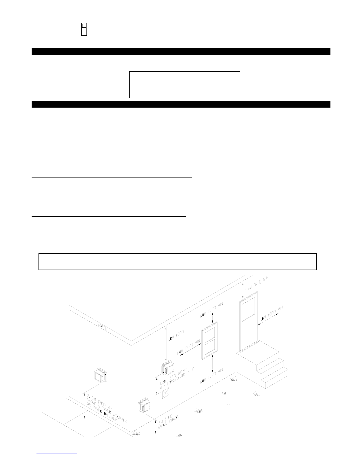
VENT HOOD TERMINATION CLEARANCES
The SideShot has been CSA Listed according to the requirements of “Mechanical Flue-Gas Exhausters” CSA Std B255-M81 and
the “Installation code for Oil burning Equipment” CSA Std B139-M91. (See Diag. A)
• A venting system shall not terminate underneath a veranda, porch, or deck, or above a paved sidewalk or a paved driveway
that is located between two buildings, and that serves both buildings.
• The exit terminals of mechanical draft systems shall not be less than 2.13m (7ft) above grade when located adjacent to a paved
sidewalk or driveway.
• A venting system shall not direct flue gases towards brickwork, siding, or other construction, in such a manner that may cause
damage from heat or condensate from the flue gases.
• A venting system shall not direct flue gases so as to jeopardize people, overheat combustible structures, or enter buildings.
A venting system shall not terminate within 1.8 m (6ft) of the following:
• A window, door or mechanical air supply inlet of any building, including soffit openings
• A gas service regulator vent outlet
• A combustion air inlet
• A property line
• A direction facing combustible materials or openings of surrounding buildings
A venting system shall not terminate within 1m (3ft) of the following:
• Above a gas meter/regulator assembly within 1m (3ft) horizontally of the vertical centreline of the regulator
• A oil tank or an oil tankfill inlet
• The inside corner of an L-shaped structure
A venting system shall not terminate within .3m (1ft) of the following:
• Above grade level or any surface that may support snow, ice, or debris
If possible, do not terminate the SS1C on a wall that faces the direction of the prevailing winds. Backdrafts by severe
winds can cause oil odors to remain in the structure and/or interrupt heating equipment operation.
6
IMPORTANT
Vent Hood and top of Plenum: Zero Clearance
Plenum front and sides: 1.3cm (1/2 inch)
Plenum rear: 7.6cm (3 inches)
P1 & P2 PRE-CYCLE FAN PROVER STATUS CHECK
The Pre-Cycle Prover Status Check is deactivated from the factory on the SS1C. Because of the
low set point of the SS1C Fan Prover (as low as .03" w.c.) cross winds may cause the Fan Prover
to close prior to a call for heat. Activating the Prover Status Check on the SS1C may cause
nuisance lockouts.
Pre-Cycle
Prover Status
Check Deactivated
9
DIAGRAM A
INSTALLATION
Tools required:
• Reciprocating Saw • 1/2", 7/16",5/8" Wrench
• Drill and 1/8", 1/4", 1/2" Bits • 1/4" Masonry Drill Bit
• Blade Screwdriver • 1/4", 5/16”, 11/32" Nut Runner or Socket
• Wire Cutter/Stripper • Hammer
• Tube Cutter
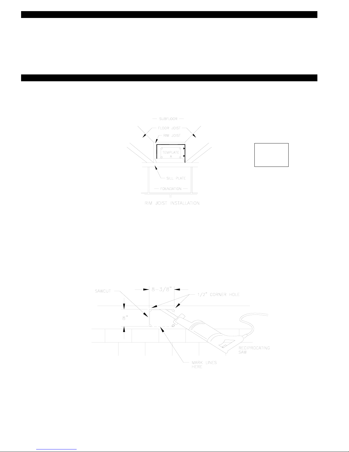
INSTALLING VENT HOOD TERMINUS
1. a) Fold template A (Page 25) along dashed line and attach in between the floor joists ensuring that it is snug against the sill
plate and right hand floor joist. Follow same procedure if floor trusses are used, (See Diagram B).
b) If the SideShot is not being installed between floor joists, attach the template to the wall it will be exiting ensuring it is level.
2. Using 1/2" bit, drill pilot holes noted on each side of the template from inside through rim-joist, wall board, siding, etc., keeping
drill bit perpendicular to the wall. 1/2" bit must be long enough to penetrate through exterior.
3. Remove template from rim-joist and attach to building exterior, aligning pilot hole markings on template with holes previously
created in Step #2.
4. Drill the four corner holes noted on the template through the building exterior. Remove the template and mark lines from the
outside edge of the holes drilled, forming a rectangle.
5. Using reciprocating saw and appropriate blade, cut a rectangular opening through the rim joist, wall board, siding, etc., on the
lines marked in step 4. The rectangular opening should be no larger than 8-3/8" in width by 8" in height, (See Diagram C).
6. Knock out block material exposing rectangular opening through the wall.
7. Apply two beads of exterior rated caulk approximately 3/8" in width at the seam of the outermost casing of the Vent Hood and
the inner flange of the Vent Hood Terminus, (See Diagram D).
8. Slide the Vent Hood through the wall while taking care installing the rain shield as shown, (See Diagram E). The nuts located on
the Vent Hood outermost casing should be facing up when sliding it through the wall. Mount Vent Hood to the exterior using
four #8 x 3" wood screws and spacers provided, (See Diagram E). Wall anchors are provided for installation into masonry wall.
7
DIAGRAM C
DIAGRAM B
Rough-In
8” Height
8 3/8” Width
 Loading...