

TJERNLUND SS2 SIDESHOT WITH UC1 UNIVERSAL CONTROL (VERSION X.02) 8504105 REV 0702, SIDESHOT SS2 Installation Instructions Manual
TJERNLUND PRODUCTS, INC.
1601 Ninth Street • White Bear Lake, MN 55110-6794
PHONE (651) 426-2993 • (800) 255-4208 • FAX (651) 426-9547
Visit our web site • www.tjernlund.com
INCLUDES NEW UC1
UNIVERSAL CONTROL
MODEL SS2
REV. 7/02
INSTALLATION INSTRUCTIONS
Recognize this symbol as an indication of important safety information!
!
OWNER INSTRUCTIONS, DO NOT DESTROY
CAUTION: The owner of the SS2 must keep the area around the vent terminal
!
free of snow, ice and debris.
NOTE: MAXIMUM FLUE GAS TEMPERATURES MUST NOT EXCEED 650oF
O
(343
SYSTEM INLET.
THESE INSTRUCTIONS ARE INTENDED AS AN AID TO QUALIFIED, LICENSED SERVICE PERSONNEL FOR PROPER INSTALLATION, ADJUSTMENT AND OPERATION OF THIS UNIT.
READ THESE INSTRUCTIONS THOROUGHLY BEFORE ATTEMPTING INSTALLATION OR
OPERATION. FAILURE TO FOLLOW THESE INSTRUCTIONS MAY RESULT IN IMPROPER
INSTALLATION, ADJUSTMENT, SERVICE OR MAINTENANCE POSSIBLY RESULTING IN FIRE,
ELECTRICAL SHOCK, CARBON MONOXIDE POISONING, EXPLOSION, PERSONAL INJURY
OR PROPERTY DAMAGE.
C) MINIMUM TEMPERATURE MUST BE 250O F (121O C) AT VENT
NOTE: Oil burner capacities exceeding 1 GPH may require the burner to be adjusted to more
efficient (12.5-13% CO2) than typical levels to maintain recommended over-fire draft
settings. See “Oil Draft Adjustment Procedure” on page 16 of this manual or consult
factory at 1-800-255-4208 with questions prior to installation.
DO NOT DESTROY. PLEASE READ CAREFULLY AND
KEEP IN A SAFE PLACE FOR FUTURE REFERENCE.
Copyright © 2002, Tjernlund Products, Inc. All rights reserved. P/N 8504105

1
Address all correspondence to:
Customer Service • Tjernlund Products, Inc. • 1601 Ninth Street • White Bear Lake, MN 55110-6794
Call us toll free at 800-255-4208, visit our web site @ www.tjernlund.com or email us at fanmail@tjfans.com.
TABLE OF CONTENTS
Description and Specifications ....................................................................................................................................1, 2
Installation Restrictions .................................................................................................................................................2
Cautions .........................................................................................................................................................................3
Safety Inspection of a Previously Used Appliance .........................................................................................................3
SideShot
®
Model SS2 Terminology ................................................................................................................................3
SideShot
®
With Integral UC1 Universal Control Board Features ...................................................................................4
LED Status & Fault Indicators .........................................................................................................................................4
Pre / Post-Purge & Prover Status Check Settings...........................................................................................................5
Vent Hood Termination Clearances
U.S. Installations............................................................................................................................................... 6
Canadian Installations .................................................................................................................................. 6, 7
Installation
Tools Required .................................................................................................................................................7
Vent System Installation .........................................................................................................................8, 9, 10
Installation of Vent Pipe ..................................................................................................................................10
Electrical Wiring
Warnings, Sequence of Operation & Internal Schematic ...............................................................................11
Wiring to Oil Fired Equipment ............................................................................................................12, 13, 14
Wiring to Gas Fired Appliance .................................................................................................................14, 15
Draft Adjustment Procedure (Oil) ..................................................................................................................................16
Draft Adjustment Procedure (Gas) ..........................................................................................................................16, 17
Combustion Air ............................................................................................................................................................. 17
Final System Operation Check Out ..............................................................................................................................17
Troubleshooting Oil Odors.......................................................................................................................................17, 18
Troubleshooting Electrical Problems .......................................................................................................................18, 19
Maintenance ............................................................................................................................................................19, 20
How to Obtain Service...................................................................................................................................................20
Warranty & Replacement Parts ...............................................................................................................................20, 21
SS2 Vent Cabinet Mounting Template (INSERTED)
SideShot
®
is a registered trademark of Tjernlund Products, Inc. for their Models SS1 & SS2 Vent Systems.
DESCRIPTION
The SS2 is a mechanical vent system designed and listed for use with natural draft oil or gas heating equipment. It is factory
assembled and wired. The SS2 automatically vents the flue gases from heating equipment to the outdoors. By recirculating
indoor air with a cooling fan, surrounding combustible materials remain at safe temperatures. After each burner cycle the SS2 will
continue to operate in post-purge mode to purge the heater and vent of residual flue gases. A factory post-purge time is set at 2
minutes and is adjustable up 16 minutes, see “Pre / Post-purge Settings” on page 5. The SS2 features a safety system consisting
of the integral UC1 Universal Control, a Fan Proving Switch and a High Limit temperature control. These devices monitor the
SS2’s performance and will interrupt the main burner if a venting malfunction is detected.
APPLICATION TABLE
Verify that the total BTU/hr. input of the heating appliance(s) fall within the inputs listed below. The BTU/hr. capacity range is
based on a maximum of 50 equivalent feet (15 meters). To determine equivalent feet, add the total length of straight vent pipe
plus 10 feet (3 meters) for each 90 degree elbow and 5 feet (1.5 meters) for each 45 degree elbow. Vent runs of over 15 linear
feet (4.5 meters) require the use of an approved, insulated vent connector to prevent problems related to condensation.
The SS2 Vent System may only be used on Flame Retention Head Oil Burners for oil installations.
Oil burner capacities exceeding 1 GPH may require the burner to be adjusted to more efficient (12.5-13% CO2) than typical
levels to maintain recommended over-fire draft settings. See “Oil Draft Adjustment Procedure” on page 16 of this manual or
consult Tjernlund at 1-800-255-4208 with questions prior to installation.
MODEL
FLAME RETENTION FAN ASSISTED
MAX. EQUIV.
OIL BURNER NATURAL & LP GAS FEET
SS2
BTU / hr.
70,000 - 168,000
BTU / hr.
40,000 - 150,000
50
BTU / hr.
40,000 - 125,000
NATURAL & LP GAS
ATMOSPHERIC
SPECIFICATIONS
Motor: 115/1/60, 3000 RPM, 1/25 HP, 1.6 FLA, Ball Bearing Permanently Lubricated.
Fan Proving Switch: Non-adjustable set point of -.40” W.C. on pressure drop.
High Limit: Manual reset N/C contacts, open at 170oF +
8oF (77oC + 5oC).
UC1 Universal Control: See UC1 Universal Control Board Features on page 4.
Cooling Fan: 115/1/60, RPM 3000, AMPS .2, CFM 105, DB Level 50.
Pre-Purge: Options (0, 15, 30, 60 seconds); Post-Purge: Factory set at 2 minutes, Options (0, 30 seconds or 1, 2, 4, 8, 16 minutes).
See page 5 for Pre / Post-purge options.
2
GENERAL INFORMATION
Each SS2 is electrically factory line tested before shipment.
After opening carton, inspect thoroughly for hidden damage. Impeller should rotate freely. If any damage is found notify freight
carrier and your distributor immediately and file a concealed damage claim.
INSTALLATION RESTRICTIONS
1. The SS2 may only be installed on flame retention head oil burners for oil installations.
2. The SS2 may not be installed on condensing type or solid fuel burning appliances, incinerators or incinerating toilets.
3. Oil installations must have a barometric draft control. The SS2 may only be installed on gas appliances equipped with a draft
hood, draft diverter or barometric draft control.
4. The SS2 may not be connected to a natural draft chimney.
5. The SS2 shall not be installed where flue gas temperatures exceed 650oF (343oC) at its inlet. Flue gas temperature verification:
A) On oil fuel, verify flue gas temperature at appliance inlet is at or above 250oF (121oC) after 5 minutes of operation during
setup. See “Oil Draft Adjustment Procedure” on page 16, step 9.
AND
B) After 15 minutes of operation, measure flue gas temperature to verify it is not more than 650oF (343oC) at SS2 inlet.
6. Vent runs of over 15 linear feet (4.5 meters) require the use of an approved, insulated vent connector to prevent problems related
to condensation.
Improper installation, adjustment, alterations, service or maintenance can cause injury, property damage or death. Refer to this
manual. For assistance or additional information consult a qualified installer, service agency or the equipment supplier.
Do not exceed the recommended input range of the SS2. Under no circumstances shall the minimum draft adjustment be used for
the larger input range of this product. Improper adjustment may result in the dispersion of flue products (carbon monoxide) into
the building interior causing carbon monoxide poisoning or death.
If oil nozzle is changed or other equipment is added perform “Draft Adjustment Procedure” on pages 16, 17 again.
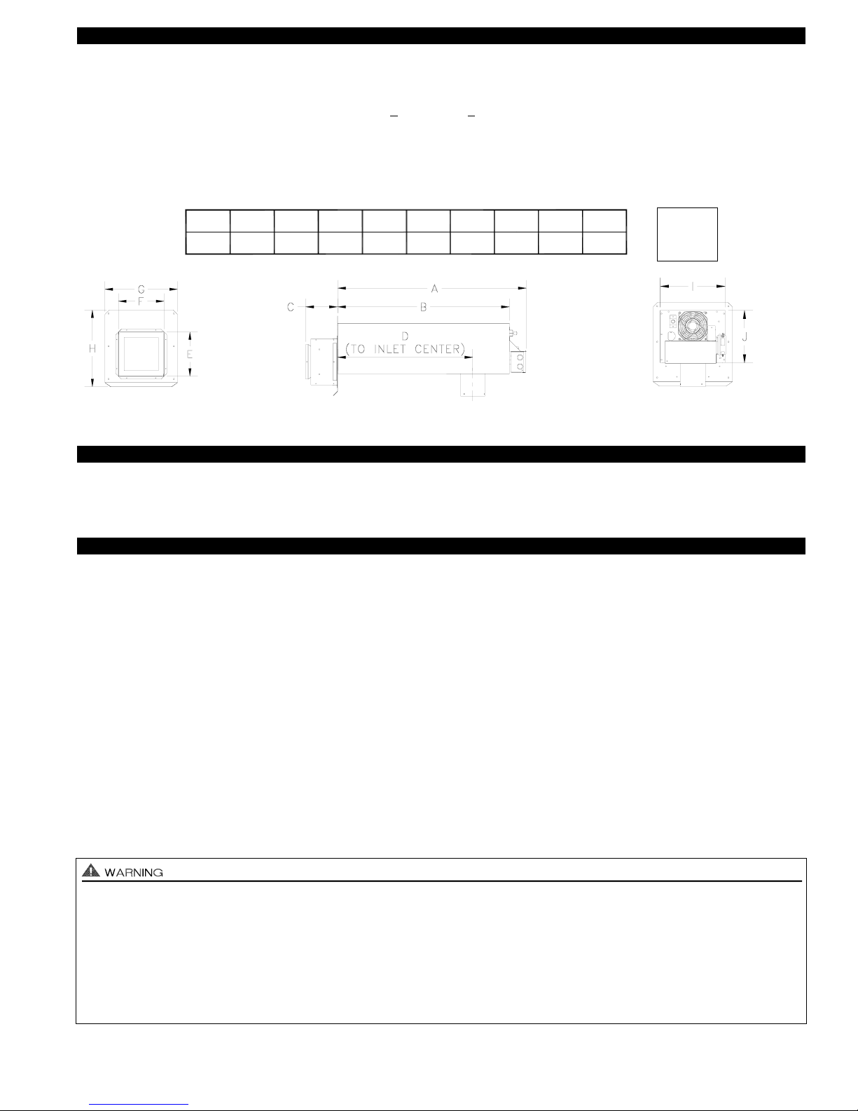
FRONT VIEW
SIDE VIEW
REAR VIEW
Rough-In
8 1/2” J
10 1/2” I
A
32 1/2"
28 1/2"B5 1/2"C22 3/8"D7 3/4"
E
8"
F
12 1/2"G13 1/4"H10 1/2"I8 1/2"
J
CAUTIONS
The SS2 must be installed by a qualified installer (an individual properly licensed and/or trained) in accordance with all local
codes or, in their absence, in accordance with the appropriate National Fire Protection Association #31, #54, #211 and the
National Electrical Code. In the absence of local codes in Canada, installations must comply with CSA Std 139 (The National
Building Code of Canada) and CSA Std 22.1 (The Canadian Electrical Code).
Failure to install, maintain and/or operate the SS2 in accordance with manufacturer's instructions may result in conditions
which can produce bodily injury and property damage.
1. The installer must verify that the BTU/hr. input of the appliance does not exceed the recommended input of the SS2. See
“Application Table” on page 1 of these instructions for maximum input capacities.
2. Disconnect power supply from the SS2 and heating equipment when making wiring connections and servicing the SS2.
Failure to do so may result in personal injury and/or equipment damage. LED #5 (RED) should be off with power removed.
3. Plan the vent layout so that the code required clearances are maintained from plumbing, wiring and combustible materials.
4. Flue gas temperatures must not exceed 650oF (343oC) at SS2 inlet. Ambient temperature must not exceed 104oF (40oC).
5. Oil fuel flue gas temperature at vent system inlet must be at least 250oF (121oC) during appliance steady state.
6. Make certain power source is adequate for the SS2 requirements. Do not add the SS2 to a circuit when the total electrical load
is unknown.
7. "Safety Inspection of a Previously Used Appliance", below must be completed when replacing a conventional chimney
venting system or when SS2 is installed on used heating equipment.
SAFETY INSPECTION OF A PREVIOUSLY USED APPLIANCE
(Perform prior to SS2 installation)
The following procedure is intended as a guide to aid in determining that an appliance is properly installed and is in safe condition
for continuing use. This procedure is based on central furnace and boiler installations and it should be recognized that generalized procedures cannot anticipate all situations. Accordingly, in some cases deviation from this procedure may be necessary to
determine safe operation of the equipment.
a. This procedure should be performed prior to any attempt at modifications of the appliance or installation of the SS2.
b. If it is determined there is a condition which could result in an unsafe operation, the appliance should be shut off and the owner
advised of the unsafe condition.
The following steps should be followed in making the safety inspection:
1. Visually inspect the venting system and determine there is no blockage or restriction, leakage, corrosion or other deficiencies
which could cause an unsafe condition.
2a. Oil Installations: Inspect burner and primary control for proper operation.
2b. Gas Installations: Conduct a gas leakage test of the appliance piping and control system downstream of the shutoff valve
in the supply line to the appliance.
Inspect burners and cross overs for blockage and corrosion.
3. Applicable only to furnaces: Inspect heat exchanger for cracks, openings or excessive corrosion. Check both the limit control
and fan control for proper operation.
4. Applicable only to boilers: Inspect for evidence of water or combustion product leaks. Determine that the water pumps are in
operating condition. Test low water cutoffs, automatic feed controls, pressure and temperature limit controls and relief valves in
accordance with the manufacturer's recommendations to determine that they are in operating order.
Excerpts from the National Fuel Gas Code (ANSI Z223.1/NFPA #54), Appendix H.
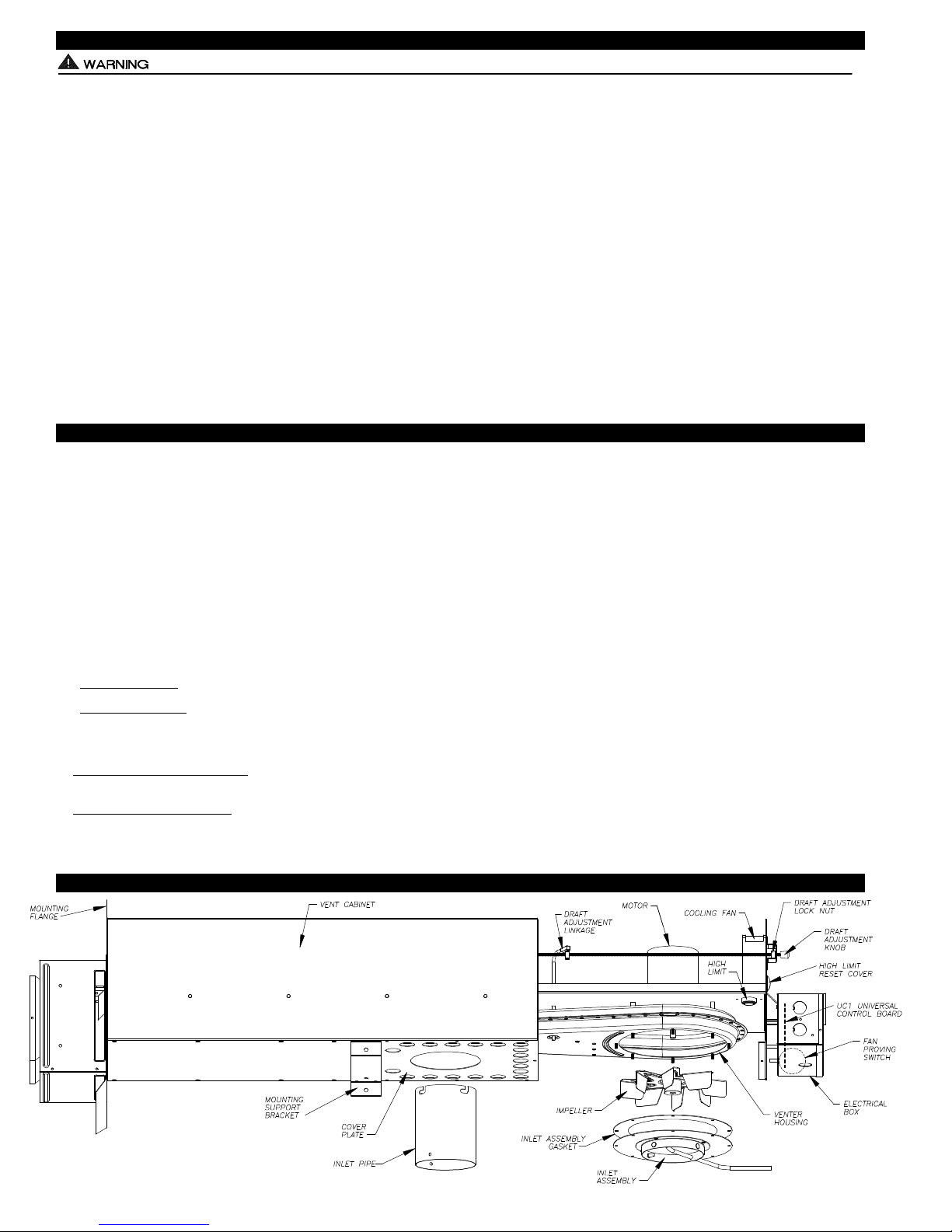
SIDESHOT®MODEL SS2 TERMINOLOGY
3
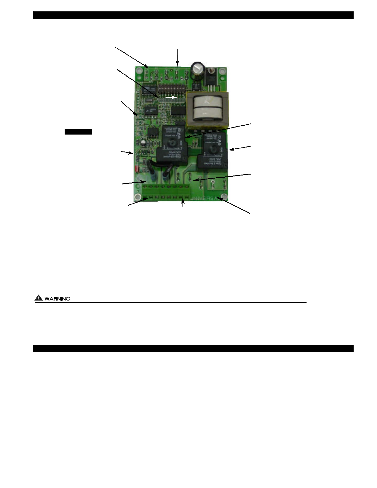
SS2 WITH INTEGRAL UC1 UNIVERSAL CONTROL BOARD FEATURES
P1 - P2 SAFETY CIRCUIT
TERMINALS
1 mA @ 5VDC.
SEE WARNING # 1.
DIP SWITCH SETTINGS
Pre-Purge (1-2)
Post-Purge (3-8)
Prover status check (9)
See “Pre / Post Purge &
Prover Status Check Dip
Switch Settings”.
LED STATUS LIGHTS
See “LED Status & Fault
Indicator Section” for details.
APPLIANCE CALL
VOLTAGE SELECTION
IMPORTANT
Place RED voltage jumper in
proper location based on
appliance call interlock voltage. SEE WARNING # 2.
J1- J2 CALL
JUMPER
Used when the call signal is
used as the “proven” return
signal to the appliance. See
wiring section for details.
APPLIANCE INTERLOCK
TERMINAL BLOCK (A-B, 1-4)
A - B - Dry Contact call. 3 mA @ 5VDC.
SEE WARNING # 1.
1 - 24 or 115 VAC intercepted call.
IMPORTANT: RED voltage jumper must
match intercepted call voltage.
2 - 24V common or 115V Neutral.
3 - Common terminal to appliance relay con-
tacts. IMPORTANT: J1-J2 jumper routes
call voltage at terminal 1 to 3. Remove
J1-J2 jumper if a different voltage source is
provided to terminal 3.
4 - Normally open terminal of appliance relay.
Will be energized from terminal 3 if safety
circuit is “proven”.
P1 P2 C GND F
LED 1 (AMBER)
LED 2 (GREEN)
LED 3 (GREEN)
LED 4 (RED)
LED 5 (RED)
DRY
24 V
115 V
A B 1 2 3 4 L N
C, GND, F AUXILIARY DEVICE
COMMUNICATION TERMINALS
2 mA @ 5VDC. For Tjernlund MAC1E or
MAC4E auxiliary devices. SEE WARNING # 1.
(1 9)
APPLIANCE
INTERLOCK
RELAY
J1 J2 XL XN
L / N - 115 VAC POWER
SUPPLY BLOCK
115 VAC / 50-60 Hz
Circuit protection provided by installer.
SEE WARNING # 3.
VENTER
MOTOR
RELAY
N M MTR
APPLIANCE INTERLOCK
RELAY
1 HP MAX LOAD across
terminals 3 & 4.
VENTER MOTOR RELAY
1 HP MAX LOAD from
terminals L to MTR & M.
XL / XN AUXILIARY DEVICE
POWER TERMINALS
115 VAC - Maximum of 0.15 Amps.
Only connect to Tjernlund auxiliary devices.
SEE WARNING # 1.
MTR & M LOAD TERMINALS
FROM VENTER MOTOR RELAY
Used to drive SS2 Motor & Cooling fan.
1 HP MAX LOAD across terminals MTR & M / N.
# 1. Power supplied by board. Do not supply power to this area or control damage may result.
# 2. Do not supply power to the appliance interlock block with the call selector in the “DRY” position.
Control damage may result if power is supplied.
# 3. Circuit protection must be provided by the installer. 16 Amps is the maximum current allowed for this device at terminal L.
A 15 Amp circuit breaker is recommended.
ETI
LED INDICATOR LIGHTS
LED #1 (Amber) Appliance call for heat.
LED #2 (Green) Safety circuit through P1 & P2 (SS2 Limit & Fan Prover) is verified “Open” upon start-up. Burner circuit is
energized with contact closure from terminal 3 to 4. Also verifies SS2 prover & limit are closed during run cycle.
LED #3 (Green) Power switched to SS2 Motor & Cooling Fan from L to MTR & M.
LED #4 (Red) Status indicator.
LED #5 (Red) 115 VAC power supplied to board. Also used as status indicator.
LED INDICATOR LIGHT STATUS & FAULTS
LED #4 & #5 Flashing Alternately = Prover start up fault. SS2 Prover contacts “Closed” across P1 & P2 upon appliance call
before SS2 is turned on. Prover status check must be activated, see page 5.
LED #4 & #5 Flashing in Unison = Fan Prover circuit is “Open” longer than 60 seconds on start-up or 10 seconds during run
cycle. Prover or Limit contacts are not staying “Closed” across P1 & P2 safety circuit.
LED #4 Flashing & #5 on Continuous = System in Pre-Purge. (Pre-Purge options 0, 15, 30, 60 seconds)
LED #5 Flashing & #4 on Continuous = System in Post-Purge. (Post-Purge options 0, 30 seconds or 1, 2, 4, 8, 16 minutes)
IMPORTANT: To reset faults, verify fault by checking the LEDs and then remove call for heat.
V
V
LED STATUS & FAULT INDICATORS
4
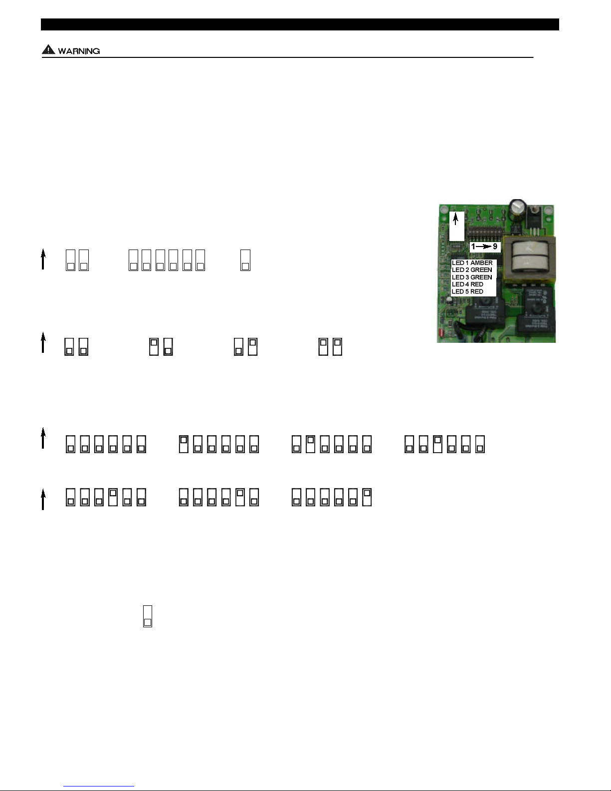
PRE / POST PURGE AND PROVER STATUS CHECK DIP SWITCH SETTINGS
PRE-PURGE SETTINGS
Remove power to SS2 and heating equipment when installing, servicing or changing dip switch settings. Failure to do so may result in
personal injury and/or equipment damage. LED #5 (RED) should not be on if 115 VAC supply power is removed from the control.
Pre-purge
Used for a Venter with longer vent runs to get draft fully established throughout the vent system prior to burner ignition. Also beneficial for negative pressure prone environments. IMPORTANT: Pre-purge settings must be shorter than primary control lockout
time unless wired prior to primary control (i.e. aquastat / thermostat).
Post-purge
A Venter post-purge has been factory set at 2 minutes. Confirm that dip switch #5 is in the up or "on" position. Oil fired equipment
requires that the post-purge be long enough to eliminate post cycle nozzle drip odor. A longer post-purge may be necessary for
longer vent runs or high heat retention, refractory lined combustion chambers. A shorter post-purge may be desired for gas installations.
DIP SWITCH NUMBERING
Pre-Purge Post-Purge
Prover Status
Check Activated
ON
2
ON
ON
1
PRE-PURGE SETTINGS
1 2 1 2 1 2 1 2
4
6
3
5
8 9
7
0 Seconds 15 Seconds 30 Seconds 60 Seconds
POST-PURGE SETTINGS
ON
43 4865 7 3 5 6 7 8 3 4 5 6 7 8 3 754 6 8
1 Minute0 Seconds 30 Seconds 2 Minutes
ON
43 4865 7 3 5 6 7 8 3 4 5 6 7 8
4 Minutes 8 Minutes 16 Minutes
P1 & P2 FAN PROVER SAFETY CIRCUIT “OPEN” UPON APPLIANCE CALL
Prover Status
Check Activated
The Prover Status Check is activated from the factory. When activated the UC1 Universal Control
checks across P1 & P2 safety circuit (SS2 Prover & Limit) to verify that the Fan Prover switch is
“Open” upon a call for heat and not stuck “Closed”. IMPORTANT: This must always be in the
9
down “Activated” position when side wall venting.
5
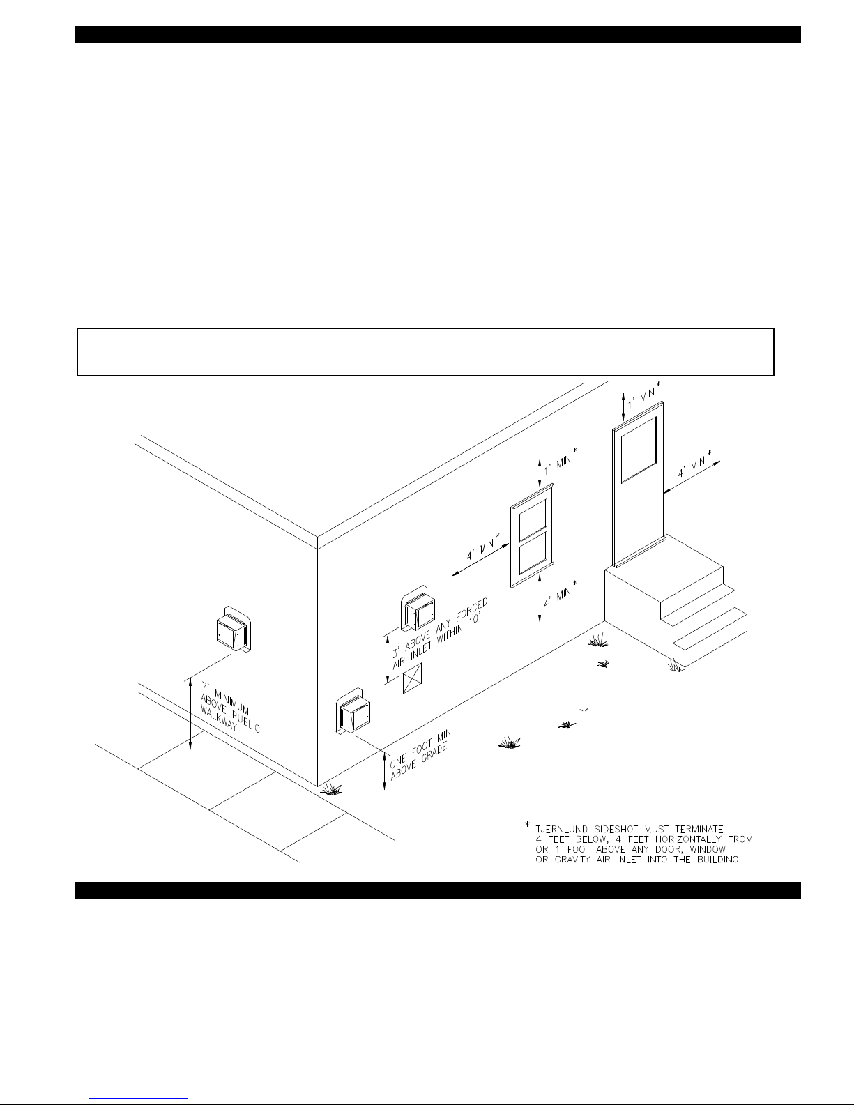
VENT HOOD TERMINATION CLEARANCES FOR U.S. INSTALLATIONS
The SS2 has been Listed according to the requirements of the National Fire Protection Association #31, #54 and #211 as
follows below, (See Diagram A).
• The exit terminals of mechanical draft systems shall not be less than 7 feet above grade when located adjacent to public walkways.
• A venting system shall terminate at least 3 feet above any forced air inlet located within 10 feet.
• The venting system shall terminate at least 4 feet below, 4 feet horizontally from or 1 foot above any door, window or gravity air
inlet into any building.
• The bottom of the vent terminal shall be located at least 12 inches above grade.
• The exit terminal shall be so arranged that the flue gases are not directed so as to jeopardize people, overheat combustible
structures or enter buildings.
• Not to be less than 10 feet from an adjacent building.
The SS2 is also Listed to terminate a minimum of 12” below, above or horizontally from a soffit, deck or adjacent sidewall.
CAUTION: The owner of the SS2 must keep the area around the vent terminal free of snow, ice and debris.
If possible, do not terminate the SS2 on a wall that faces the direction of the prevailing winds. Backdrafts by
severe winds can cause oil odors to remain in the structure and/or interrupt equipment operation.
DIAGRAM A
VENT HOOD TERMINATION CLEARANCES FOR CANADIAN INSTALLATIONS
The SS2 has been Listed according to the requirements of “Mechanical Flue-Gas Exhausters” CSA Std B255-M81 and the
“Installation code for Oil burning Equipment” CSA Std B139-M91, (See Diagram A1).
• A venting system shall not terminate underneath a veranda, porch, or deck, or above a paved sidewalk or a paved driveway
that is located between two buildings, and that serves both buildings.
• The exit terminals of mechanical draft systems shall not be less than 2.13m (7ft) above grade when located adjacent to a paved
sidewalk or driveway.
• A venting system shall not direct flue gases towards brickwork, siding, or other construction, in such a manner that may cause
damage from heat or condensate from the flue gases.
• A venting system shall not direct flue gases so as to jeopardize people, overheat combustible structures, or enter buildings.
6
 Loading...