

Page 1
TJERNLUND PRODUCTS, INC.
1601 Ninth Street • White Bear Lake, MN 55110-6794
PHONE (800) 255-4208 • (651) 426-2993 • FAX (651) 426-9547
Visit our web site • www.tjernlund.com
READ OWNERS INSTRUC-
TIONS CAREFULLY PRIOR
TO INSTALLATION.
THESE INSTRUCTIONS MUST
REMAIN WITH EQUIPMENT.
DO NOT DESTROY.
SURE DRYTMSHOWER DRYING SYSTEM
MODEL SD140
©2012 TJERNLUND PRODUCTS, INC. ALL RIGHTS RESERVED P/N: 8504188
DESCRIPTION
The Sure Dry™ SD140 Shower drying system quietly circulates dry air from an adjoining room into the shower enclosure to efficiently
dry caulk, grout, tile and glass surfaces. Sure Dry Systems minimize mold/mildew growth and grout damage by accelerating surface
drying time up to 80%.
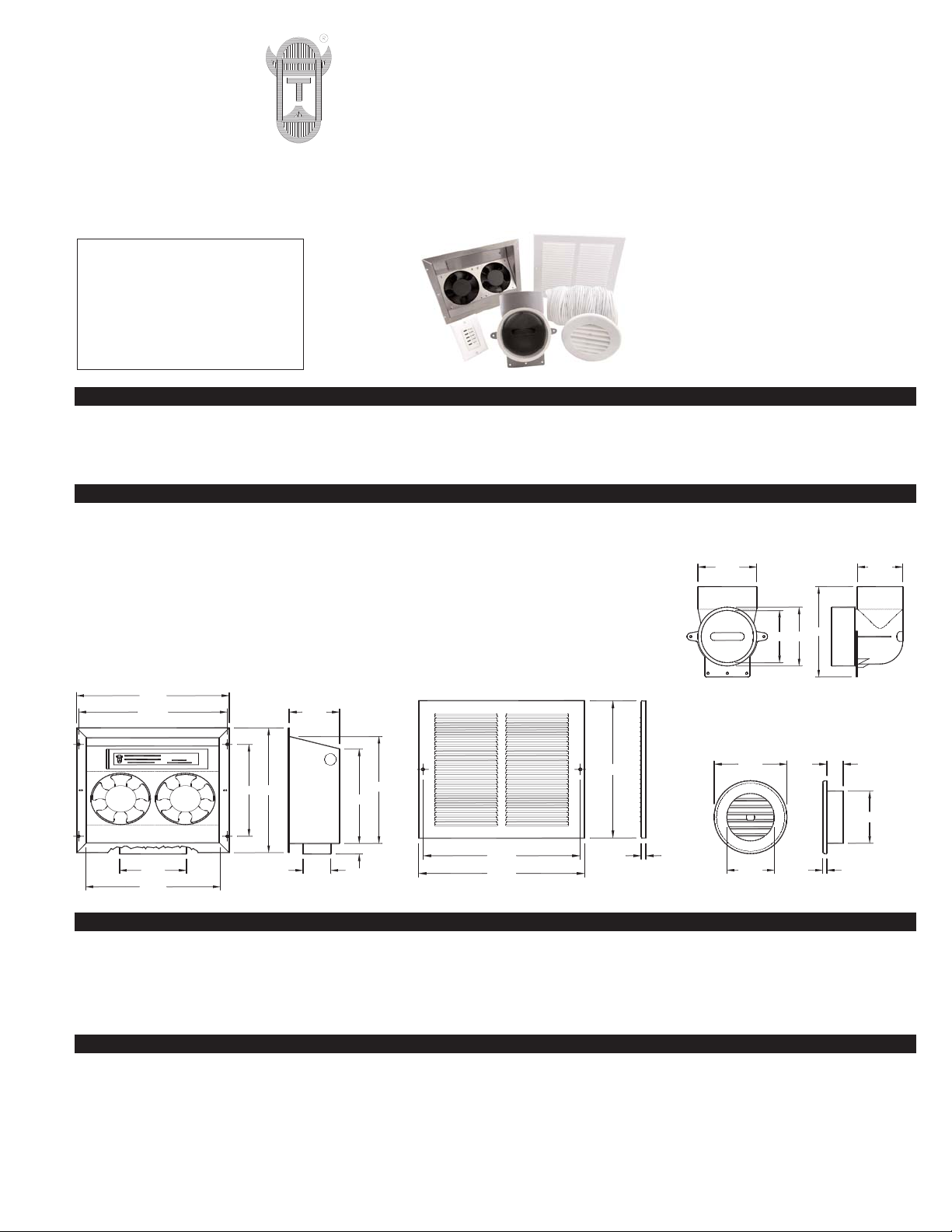
SPECIFICATIONS & COMPONENTS
GENERAL INFORMATION
Every Tjernlund Sure Dry™ fan is electrically factory line tested before shipment.
After opening carton, inspect thoroughly for shipping damage. Impellers should rotate freely and all electrical wires and connections
should be secured. If any damage is found, notify freight carrier and your distributor immediately and file a concealed damage claim.
INSTALLATION RESTRICTIONS
The Sure Dry™ System must be installed by a qualified installer in accordance with these instructions and all local codes or in their
absence in accordance with the latest editions of the International Residential Code and International Electrical Code. Improper installation can create a hazardous condition such as fire, electric shock or personal injury. To reduce these risks significantly, use this device
only in the manner intended by the manufacturer. If you have questions about proper usage of this device, call Tjernlund Products at
800-255-4208 or email us at fanmail@tjfans.com.
MODEL SD140
Blower: 140 cfm
Motor: 120 Volts ~ 60 Hz; 0.45 amps
Rough In: Blower rough opening: 8 1/4” Height x 10 1/4” Width
Supply Elbow rough opening through tile: 4 3/4" diameter
Digital Timer: Decorator switch plate style fits single or multi-gang boxes, 5 settings - White
FIGURE 8061031
MODEL SD140
5 1/8" 2 1/8"
7 1/4"
8 1/4"
3 7/8"11 5/16"
11 5/8"
3/4"
7"
10 1/4"
9 1/2"
FIGURE 8061030
4 1/2" 3 1/2"
7"
4"
4 1/2"
INTAKE GRILLE, WHITE, WITH SCREWS
11 3/4"
11 1/8"
9 3/4"
5/16"
FIGURE 8061028
5/16"
3 15/16"
3 1/2"
5 1/2" 1 1/4"
SD140 BLOWER HOUSING
SD140 INTAKE GRILLE - WHITE
SHOWER SUPPLY GRILLE
WHITE - (COLOR OPTIONS AVAIL.)
SHOWER SUPPLY ELBOW
Page 2
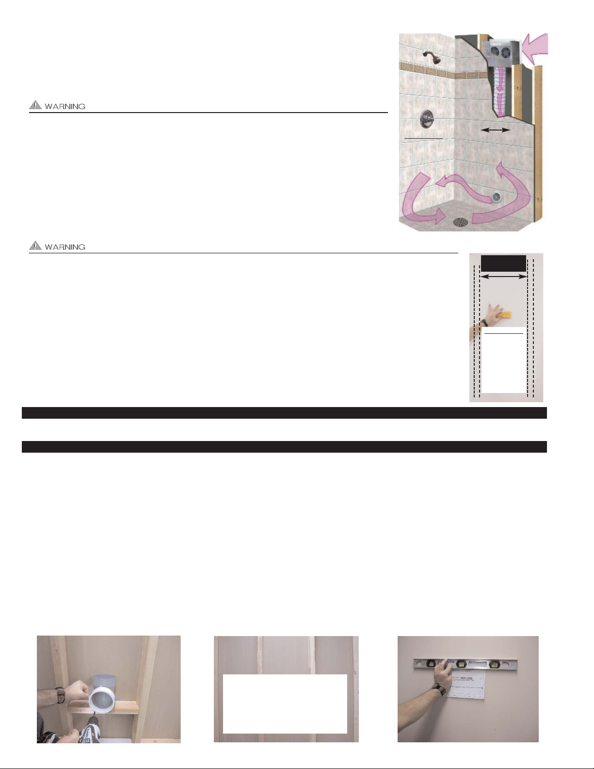
Always disconnect the Sure Dry™ Fan or timer from its power source before installation and servicing.
IMPORTANT: An in depth investigation of the wall layout is required prior to installation. Avoid a
stud wall section that is a path for plumbing supply lines, drains and vents. Avoid a stud wall section that is insulated or being used as a return air duct for a forced air system. Pick the best location
based on clear routing of the supply duct, sound transfer concerns, electrical supply routing and
air drying paths. Make sure the wall cavity is at least 10 1/2" wide between inside stud edges.
• The Sure Dry™ may not be used to exhaust hazardous or explosive materials or vapors.
• The Sure Dry™ may not be installed in a ceiling.
• The Sure Dry™ may not be installed in an outside wall.
• The Sure Dry™ may not be installed in a wall rated as a “fire wall.”
• The Sure Dry™ may not be used to move air from one floor (story) to another floor.
• The Sure Dry™ may not be used in a window.
Disrupt power at circuit breaker to outlets & switches from the electrical power source you will be working
with.
When manually sawing through sheetrock stop if you detect the saw blade coming in contact with any wiring or
plumbing. Investigate further to determine if it is possible to safely continue to use this wall cavity space. Switch to
another stud wall cavity if necessary.
BEFORE YOU START:
Determine the stud wall section that you want to use to mount the SD140 in. IMPORTANT: Wall studs must be
spaced a minimum of 10 1/2” between inside edges, (See Diagram A). NOTE: If attempting to install the SD140
with an existing shower and not performing a complete remodel or retrofit, mark inside edges of studs the Sure
Dry™ will be installed between and verify there is at least 10 1/2” between the inside edges. Slide a stud finder
down the wall between the studs to verify the stud wall cavity is completely open, (See Diagram B).
TOOLS REQUIRED
Sheetrock Saw Drill Tin Snips Phillips & Straight Screwdrivers Level Tape Measure Utility Knife or Scissors Wire Stripper
REMODEL OR NEW CONSTRUCTION INSTALLATION
1. When installing the SD140, locate possible installation locations by examining the inside and outside shower areas for non-obstructed
wall stud cavities. Avoid wall stud cavities that have plumbing or electrical wires within them. Pick the best location based on clear
routing of flex duct, sound transfer concerns, electrical supply routing. Make sure the wall cavity is at least 10 1/2" wide between
inside stud edges, (See Figures A & B).
2. On the shower side of the wall before any materials have been fastened to the studs, define where the shower air Supply Grille will
be located. Make sure the height of the Shower Grille is above the highest water level obtainable in the shower. Mount the gray &
white Supply Elbow between 2 studs within the wall cavity chosen in Step 1. Make sure the oval end of elbow points up. The use of
an additional wall framing piece (2 x 4 or 2 x 6) or is required to solidly mount elbow. Mount Supply Elbow above maximum water
level, (See Figure C).
3. In the wall cavity where the supply elbow has been mounted, define a location for the Blower. This location should be towards the top
of the wall cavity but no closer than 3" from the ceiling on the other side of the wall. Once a target location has been determined, find
the center point between the studs and poke a small hole thru the wall and verify the location is acceptable from the other side of the
wall, (See Figure D).
FIGURE A
IMPORTANT: Wall cavity between studs
must be completely open between Blower
and Supply Elbow. Studs must have a
minimum of 10 1/2” between inside edges.
FIGURE B
Wall studs must
have a minimum
of 10 1/2”
between them.
BLOWER
OPENING
IMPORTANT:
Wall cavity
between studs
must be com-
pletely open
between
Blower and
Supply Elbow
FIGURE D
FIGURE EFIGURE C
PICK A STUD WALL CAVITY THAT IS
UNOBSTRUCTED AND ALSO CONFIRM BLOWER INTAKE LOCATION IS
ACCEPTABLE ON WALL OPPOSITE
SHOWER. POKE A SMALL HOLE
THRU WALL TO DETERMINE IF
BLOWER LOCATION IS SUITABLE.
Page 3

4. From the Blower side of the wall, locate the small hole created in Step 3 and if ok, position the SD140 Blower cut out template.
Top line of Blower template should not be closer than 3” to the ceiling. Level and tape the template to the wall, (See Figure E).
Use a sheetrock saw with caution to remove sheetrock between template lines, (See Figure F).
5. Remove the Fan assembly from the Blower housing by using a screw driver to pry top flang over 2 Blower case extruded dimples and
set aside for later use. Insert the Blower housing into the hole with the oval supply duct connection facing down and mark the (4) corner holes with a pencil. Drill out holes with 3/16” bit, carefully tap in wall anchors and secure housing to the wall with screws provided,
(See Figure G).
6. Install the provided flexible oval duct with (2) 1/4 x 3/8”
sharper point self tapping screws on oval Blower housing flange making sure that screw head is below and
pinches metal ring in flex duct on both sides. Stretch
flex duct down to Supply Elbow and cut to length with a
metal snips. Make sure the duct is stretched and is as
straight a run as possible. Excessive flex duct material
and bends will reduce fan performance and lengthen
shower drying times. Install the flexible oval duct with
(2) 1/4 x 3/8” duller point self tapping screws on Supply
Elbow making sure that screw head is above and
pinches metal ring in flex duct on both sides, (See
Figure H).
SHOWER SIDE FINISHING
1. Finish remodeling the shower including sealing the area around where the elbow enters the shower. Excess pipe from the elbow into
the shower is acceptable at this point. Make sure all tiling and grouting has been completed before moving forward. Place the provided
sheet metal protection plate over the supply elbow extension and tape to tile wall, (See Figure I).
2. Use a reciprocating saw, grinder, dremmel tool, etc., to cut off the elbow extension until it is flush with the metal plate and remove,
(See Figure J). Once metal plate is removed, careful cleanup on Supply Elbow can be done so it is flush with tile.
3. Test fit the Shower Grille. Make sure it can be installed flush to the shower tile surface and make adjustments on Supply Elbow with
grinder or dremmel tool if necessary. Silicone seal the Shower Grille in place using high quality silicone bath caulk. Place large beads
of silicone bath caulk on inlet leading edge of Shower Grille and on outside flange of Shower Grille and insert in Supply Elbow.
Smooth excess caulk bead around Supply Grille and tile, (See Figure K). Rotate Shower Grille louvers in desired direction.
WIRING
The following steps involve electrical wiring and should only be performed by a licensed electrician and / or adhere to all local, state and
national electrical codes.
Locate and install the timer switch preferably by existing exhaust and light switches, while following all local, state and national electrical
codes. The fan unit consumes less than 50 watts when operating so use of existing power circuit for the lights in the shower area is
often times acceptable. MAKE SURE THE POWER CIRCUIT IS OFF BEFORE CONTINUING. A GFI CIRCUIT IS REQUIRED.
FIGURE J
FIGURE KFIGURE I
FIGURE G
FIGURE H
FIGURE F
Page 4

1. Route the switched power load wiring from the switch to the Blower housing. Use one of the (4) provided knockouts in the Blower
housing. Route a minimum of 12" of wire inside the Blower housing. If using 14 gauge nonmetallic sheathed cable (Romex or equivalent), strain relief the wiring at the Blower housing using the provided black plastic nonmetallic cable strain relief. If using some other
wire type, strain relief the wire at the Blower housing using an approved strain relief method, (See Figure L).
2. Install the dual Fan assembly into the Blower housing making sure to route all wires thru the access hole in the front of the Fan
assembly. To install the Fan assembly, hook the top edge of the Fan assembly under the 2 extruded dimples located on the top of
the Blower housing. Push the Fan assembly into the Blower housing until the assembly snaps into place, (See Figure M).
3. Wire the Fan assembly to the Timer switch wiring as defined in the wiring diagram below. Once complete, install Fan assembly electrical coverplate with the screw provided and Timer switch cover plate. Install the white Intake Grille over the Blower housing with the
provided white headed screws. The grille louvers should face upwards so fans can not be viewed through the grille, (See Figure N).
MAINTENANCE
The Sure Dry™ fan compartment should be inspected annually and carefully cleaned or vacuumed with a bristle brush head if necessary. The motors are permanently lubricated and require no maintenance.
REPLACEMENT PARTS AND WARRANTY
Component Part Number Component Part Number
Digital Timer - White 950-9300 SD140 Dual Fan Assembly 950-9310
Intake Grille - White 950-9320 Shower Supply Grille - White 950-9321
TJERNLUND LIMITED ONE YEAR WARRANTY
Tjernlund Products, Inc. warrants to the original purchaser of this product that the product will be free from defects due to faulty material or workmanship for a period of (1)
year from the date of original purchase or delivery to the original purchaser, whichever is earlier. Remedies under this warranty are limited to repairing or replacing, at our
option, any product which shall, within the above stated warranty period, be returned to Tjernlund Products, Inc. at the address listed below, postage prepaid. THERE ARE
NO WARRANTIES WHICH EXTEND BEYOND THE DESCRIPTION ON THE FACE HEREOF, AND TJERNLUND PRODUCTS, INC. EXPRESSLY DISCLAIMS LIABILITY
FOR INCIDENTAL OR CONSEQUENTIAL DAMAGES ARISING FROM THE USE OF THIS PRODUCT. THIS WARRANTY IS IN LIEU OF ALL OTHER EXPRESS WARRANTIES AND NO AGENT IS AUTHORIZED TO ASSUME FOR US ANY LIABILITY ADDITIONAL TO THOSE SET FORTH IN THIS LIMITED WARRANTY. IMPLIED
WARRANTIES ARE LIMITED TO THE STATED DURATION OF THIS LIMITED WARRANTY. Some states do not allow limitation on how long an implied warranty lasts,
so that limitation may not apply to you. In addition, some states do not allow the exclusion or limitation of incidental or consequential damages, so that above limitation or
exclusion may not apply to you. This warranty gives you specific legal rights and you may also have other rights which may vary from State to State. Send all inquiries
regarding warranty work to Tjernlund Products, Inc. 1601 9th Street, White Bear Lake, MN 55110-6794. Phone (651) 426-2993 • (800) 255-4208 • Fax (651) 426-9547 •
Email fanmail@tjfans.com.
GROUND
120 VAC
50/60 Hz
N
L1
SD140 FAN TIMER
JUNCTION BOX
BLACK RED
WHITE
GFI
PROTECTED
FAN
GREEN
SD140 FAN JUNCTION BOX
WHITE
BLACK
WHITE
BLACK
FAN
WIRE NUTS
DIGITAL
TIMER
GREEN
SURE DRYTMMODEL SD140 FAN & TIMER WIRING CONNECTIONS
FIGURE M
FIGURE N
FIGURE L
 Loading...