

Page 1
Copyright © 2011, Tjernlund Products, Inc. All rights reserved. P/N 8504173
REV. 2/11
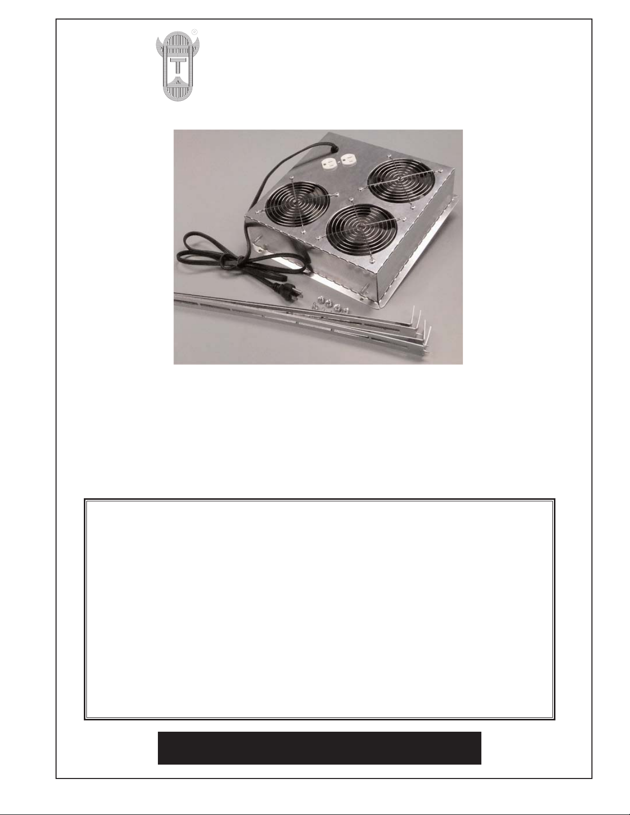
MODEL RVB3 ROOF VENT BOOSTER FAN
INSTALLATION INSTRUCTIONS
OWNER INSTRUCTIONS, DO NOT DESTROY.
THIS DEVICE MUST BE INSTALLED BY A
QUALIFIED PERSON IN ACCORDANCE WITH
ALL LOCAL CODES.
READ INSTRUCTIONS CAREFULLY PRIOR TO
INSTALLATION AND OPERATION.
DO NOT DESTROY. PLEASE READ CAREFULLY AND
KEEP IN A SAFE PLACE FOR FUTURE REFERENCE.
TJERNLUND PRODUCTS, INC.
1601 Ninth Street • White Bear Lake, MN 55110-6794
PHONE (800) 255-4208 • (651) 426-2993 • FAX (651) 426-9547
Visit our web site • ww w.tjernlund.com
Page 2
DESCRIPTION
A Powered Roof Vent Booster (RVB) is a simple and safe way to increase attic ventilation. RVB’s allow you to avoid the
hassle and danger of working on top of the roof. They install from inside the attic against the underside of standard roof
vents with openings up to 11” square. They boost ventilation by over 3 times that of passive roof vents, helping to keep
the attic space the same temperature as the outside. NOTE: Use of the RVB will aid in the prevention of ice dams, but
does not reduce existing ice dams.
Adjustable arms secure the booster in place between roof rafters/trusses up to 32” across. No wiring is necessary, just
plug the Powered Roof Vent Booster into an outlet. Operates on only 60 Watts. When using more than 1 RVB, plug one
fan into another for multiple unit operation through a single power source (8 unit maximum). Position Powered Roof Vent
Booster(s) over roof vents near and above areas with severe ice damming.
SPECIFICATIONS
RECOMMENDED METHODS AND PATTERNS OF OPERATION
How to determine the number of Powered Roof Vent Boosters needed:
Calculate the cubic area of the attic by multiplying the Length x Width x (1/2) Height (assumes a pitched roof). Divide
this number by 10 to determine the minimum CFM necessary to fully ventilate the space in 10 minutes.
Example: 20' wide x 40' long x (1/2) 6' high attic = 2400 cubic ft.
2400 cubic ft. ÷ 10 minutes = 240 CFM of ventilation. Choose one RVB3.
Choose one RVB3 for every 300 CFM, rounding up.
Increasing Ventilation to Eliminate Ice Dams
Ice Dams are a common problem in regions that regularly have snow. They are caused by upper portions of a roof surface warming to over 32 degrees, which melts the snow. The resulting water refreezes near the roof’s edge where surface temperatures are lower, forming a dam of ice. When the water can no longer flow down over the dam it backs up
the roof and underneath shingles causing interior water damage and shingle damage.
Generally Recommended Procedures for Eliminating Ice Dams:
• Find and seal air leaks from the heated living space into attic around openings for bath fans, heating or dryer exhaust ducts.
• Add insulation to the floor of the attic. Remove insulation from soffit openings in attic space.
• Ventilate the space using the RVB so that the underside of the upper roof surface stays below 32 degrees. This may
be easiest by locating RVB units over roof vents near and above areas that have had ice dams in the past. Make sure
that soffit vents and roof vents are clear of debris or other obstructions.
Increasing Ventilation to Exhaust Summertime Heat from Attics
Roof Vent Boosters can be used in place of traditional attic fans to increase attic ventilation and decrease cooling costs
during the hot summer months. Exhausting pent-up attic heat will decrease the amount of energy needed to cool your
home. If a large amount of ventilation is required, the RVB units can be daisy-chained with one unit plugged into the
next so that only one power source is needed for all fans (8 unit maximum).
INSTALLATION
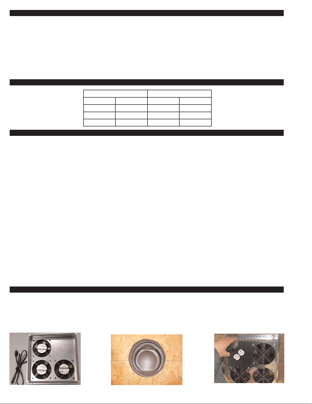
1. Apply included foam tape to exterior edge of RVB. This will decrease leakage of air flow from the fans and minimize any unit
vibration, (See Diagram A).
2. Center RVB over opening of existing roof vent opening, (See Diag. B). Locate electrical outlet side on roof peak side, (See Diag. C).
1
Dimensions/Performance Electrical
Length 12” Voltage 115 VAC
Width 12” RPM 3000
Depth 3.5” Watts 60
CFM 300 Amps 0.9 (max.)
Diagram A
Diagram B, Typical Roof Vent
Opening View from Inside Attic
Diagram C
Page 3

3. Temporarily secure the RVB to the underside of the roof sheathing with the included screws through the holes in each corner of the
RVB flange. IMPORTANT: 3/8” screws are short enough to not penetrate the roof deck. Do not use longer screws.
4. Bend the included mounting brackets against a soft radius (rounded edge) to straighten them. If a small kink or bend remains, that
is acceptable as the brackets will retain their strength and further straighten as the mounting nuts are added in Step 7.
5. Bend the end of each mounting bracket on the scored side (a V-shaped hole with be on that side) to create a 1.5” flange and
angled point, (See Diagram E and F).
6. Place one of the brackets over the left hand metal stud on the side of RVB housing. Adjust which notch the stud fits into so that the
bracket is flush against the left hand joist/truss. Use a hammer to drive the angled point into the joist/truss for a temporary hold,
(See Diagram G). Repeat for right hand side of bracket. Install bracket on opposite RVB housing side in same fashion.
7. Firmly secure the RVB to roof joist/truss with provided screws into hole on flange of the mounting brackets, (See Diagram H).
Lock the mounting brackets in place against the RVB by tightening the included nuts onto each metal stud, (See Diagram I).
8. Plug RVB into an electrical outlet or an existing installed RVB.
WARRANTY
2
Diagram D Diagram FDiagram E
Diagram G
Diagram H Diagram I
TJERNLUND LIMITED 1 YEAR WARRANTY
Tjernlund Products, Inc. warrants to the original purchaser of this product that the product will be free from defects due to faulty material or workmanship
for a period of (1) year from the date of original purchase or delivery to the original purchaser, whichever is earlier. Remedies under this warranty are
limited to repairing or replacing, at our option, any product which shall, within the above stated warranty period, be returned to Tjernlund Products, Inc.
at the address listed below, postage prepaid. THERE ARE NO WARRANTIES WHICH EXTEND BEYOND THE DESCRIPTION ON THE FACE HEREOF, AND TJERNLUND PRODUCTS, INC. EXPRESSLYDISCLAIMS LIABILITY FOR INCIDENTAL OR CONSEQUENTIAL DAMAGES ARISING FROM
THE USE OF THIS PRODUCT. THIS WARRANTY IS IN LIEU OF ALL OTHER EXPRESS WARRANTIES AND NO AGENT IS AUTHORIZED TO
ASSUME FOR US ANY LIABILITY ADDITIONALTO THOSE SET FORTH IN THIS LIMITED WARRANTY. IMPLIED WARRANTIES ARE LIMITED TO
THE STATED DURATION OF THIS LIMITED WARRANTY. Some states do not allow limitation on how long an implied warranty lasts, so that limitation
may not apply to you. In addition, some states do not allow the exclusion or limitation of incidental or consequential damages, so that above limitation
or exclusion may not apply to you. This warranty gives you specific legal rights and you may also have other rights which may vary from state to state.
Send all inquiries regarding warranty work to Tjernlund Products, Inc. 1601 9th Street, White Bear Lake, MN 55110-6794. Phone (651) 426-2993 • (800)
255-4208 • Fax (651) 426-9547 • Email fanmail@tjfans.com.
 Loading...