

Page 1
When using the RTS-Series mounting kit, vent pipe manufacturer’s clearances to combustibles and recommended support
and installation guidelines must be adhered to. The RTS mounting location must be based on “Termination Clearances” found
in the Rooftop Inducer instruction manual and/or local codes.
ASSEMBLY AND INSTALLATION OF RTS-SERIES ROOF MOUNTING KIT
Determine mounting location considering adequate roof support and termination clearances.
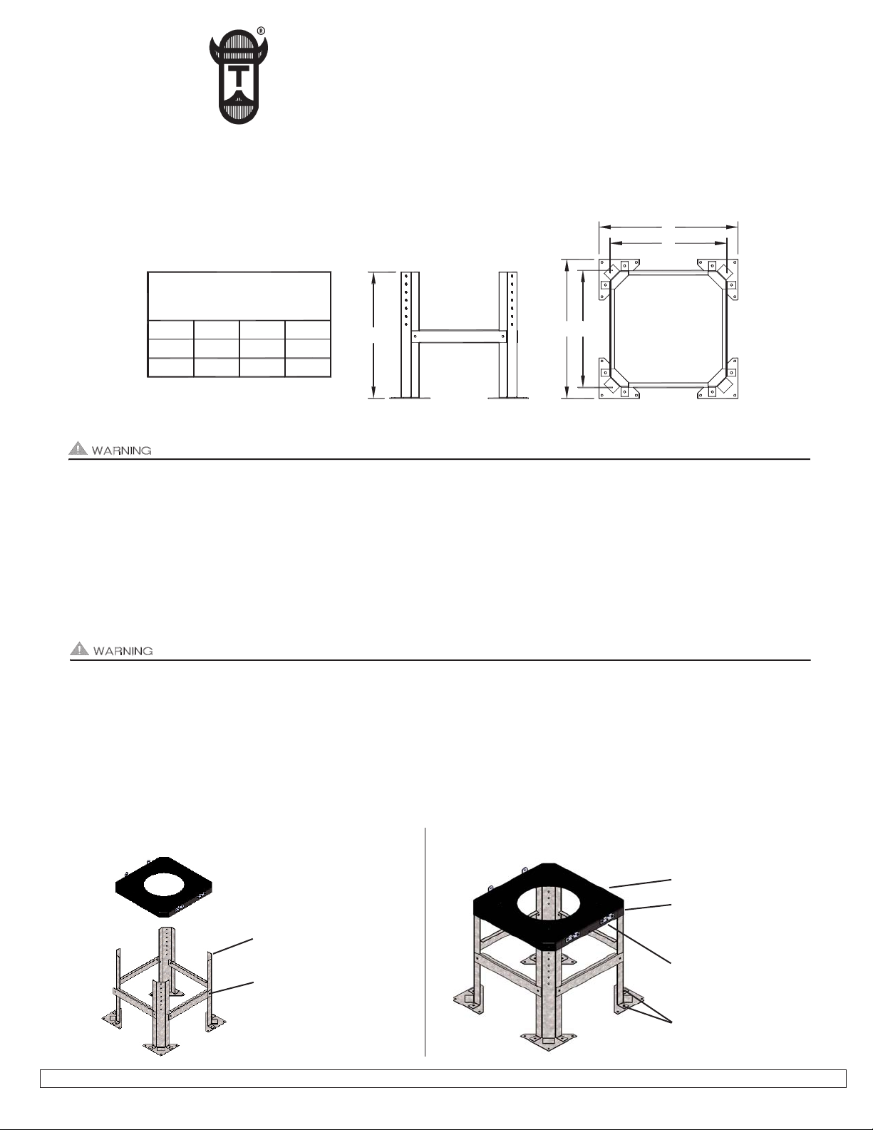
1. The Rooftop Inducer base can be adjusted from 10” to 16” in 1” increments. Each RTS leg should be cut down a maximum of 3/8”
above the top of desired adjustment hole so Rooftop Inducer base holes line up with leg holes. Assemble (4) RTS legs with (4)
support cross braces and (2) bolts and lock nuts on each brace, (See Diagram A).
Rooftop motor side is heavy. Housing hinge pins should be removed for easier installation. When removing motor side, use
extreme caution so internal parts such as the impeller are not damaged.
2. Make sure that the Rooftop Inducer base hinges are positioned so that Inducer swings towards the desired direction. The electrical
whip of the Rooftop Inducer is also located on the hinged side. Place Rooftop Inducer Base on top of RTS legs and insert (4) bolts
through Inducer Base corners and legs and firmly tighten with (4) lock nuts. Attach feet to legs and firmly tighten (2) lock nuts on each
leg, (See Diagram B).
3. Use appropriate fasteners to attach RTS stand to roof. Fasteners should be installed in at least (2) holes on each foot. Mounting holes
and vent pipe roof penetrations must be adequately sealed and flashed to prevent leakage, (See Diagram B).
RTS SERIES ROOFTOP INDUCER MOUNTING KITS
Constructed out of 16 gauge G90 galvanized steel
Rooftop Inducer base adjustable in 1” increments from 10” to 16”
Tjernlund Products, Inc. • 1601 Ninth Street • White Bear Lake, MN 55110 • (651) 426-2993 • (800) 255-4208 • FAX (651) 426-9547 • www.tjernlund.com
P/N 8504161
DIAGRAM A
DIAGRAM B
CUT LEGS DOWN A MAXIMUM
OF 3/8” ABOVE DESIRED
ADJUSTMENT HOLE.
ASSEMBLE RTS KIT WITH (2)
BOLTS AND LOCK NUTS ON
EACH LEG SUPPORT CROSSBRACE.
TJERNLUND PRODUCTS, INC.
1601 Ninth Street • White Bear Lake, MN 55110-6794
PHONE (800) 255-4208 • (651) 426-2993 • FAX (651) 426-9547
Visit our web site • www.tjernlund.com
ROOFTOP INDUCER BASE
INSERT (4) BOLTS AND LOCK
NUTS THROUGH INDUCER BASE
CORNERS AND LEGS AND FIRMLY
TIGHTEN.
POSITION WITH HINGES TOWARD
DESIRED INDUCER SWING OPEN
DIRECTION. ELECTRICAL SERVICE IS ALSO ON HINGED SIDE.
ATTACH FEET TO LEGS AND
FIRMLY TIGHTEN (2) LOCK NUTS.
C
C
B
B
A
SIDE VIEW TOP VIEW
RTS SERIES ROOF MOUNT KIT
DIMENSIONS
(ALL DIMENSIONS ARE IN INCHES)
ABC
17.2514.5015.75
RTS8
RTS12
15.75 17.00 19.75
FIGURE 8053001
 Loading...