

Page 1
When using the RMK-Series mounting kit, it is recommended to use vent pipe rated for
reduced clearances to combustibles. Vent pipe manufacturer’s clearances must be
adhered to.
RMK mounting location must be based on “Termination Clearances” found in the AutoDraft instruction manual for U.S. and Canadian installations.
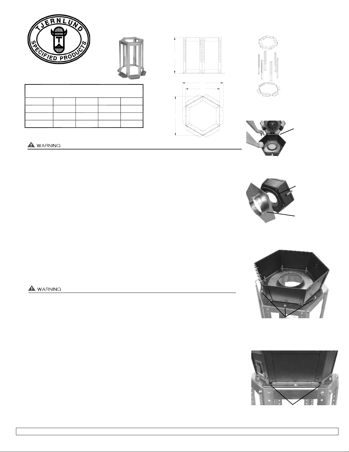
The maximum vent diameter that can fit inside the RMK is based on the C dimension in the table
above. Use tapered reductions if necessary. Inlet Collar diameters are 8” for the FSAD-8 /
VSAD-8, 10” for the FSAD-10 / VSAD-10 and 12” for the FSAD-12 / VSAD-12.
ASSEMBLY AND INSTALLATION OF RMK-SERIES ROOF MOUNTING KIT
Determine mounting location considering adequate roof support and termination clearances.
1. Assemble base of RMK, (6) legs of RMK and top of RMK. The RMK legs are adjustable from
24.38” down to 9”. Legs should be cut down to necessary height. Make sure Auto-Draft
Inlet Collar can be fully inserted into vent pipe before cutting legs. The RMK-8 and RMK-10
are assembled with (2) provided bolts and lock nuts on the top and bottom of each leg. The
RMK-12 is assembled with (4) bolts and lock nuts on the top and bottom of each leg, (See
Diagram A).
2. Mark bolt hole locations for RMK bottom base flanges and secure RMK to roof with appropriate
installer supplied hardware.
Auto-Draft® motor side is heavy. Housing hinge pin should be removed for easier installation. Support Inducer base when removing hinge pin. When removing motor side, use
extreme caution so internal parts such as the impeller are not damaged, (See Diagram B).
3. Lay a bead of high-temp silicone close to outer edge of Inducer Base. Insert the Inlet Collar
through the Mounting Plate provided with Auto-Draft Inducer and secure Mounting Plate to
Auto-Draft base with provided nuts, (See Diagram C).
4. With RMK fully assembled at the necessary height, secure Mounting Plate with Inducer base
and Inlet Collar to RMK top with the (6) provided bolts and lock nuts, (See Diagram D).
5. Secure the Inlet Collar to vent pipe with self tapping stainless steel screws, installer supplied.
Make sure screws are long enough to adequately secure Inlet Collar to vent pipe. Make sure
vent pipe is adequately installed, supported and sealed.
6. Reattach Auto-Draft® motor side to Base making sure that hinge pin is fully inserted in hinges,
(See Diagram B).
7. Seal around the Inducer base and Mounting Plate with high-temp silicone. Make sure it is
watertight. Do not block the (6) corner drain holes, (See Diagram E).
8. Make sure that vent pipe roof penetration is adequately flashed and sealed to prevent leakage.
RMK SERIES ROOF MOUNTING KITS
Constructed out of rugged 5052 Aluminum.
Adjustable from 9” to 24” in height.
Tjernlund Products, Inc. • 1601 Ninth Street • White Bear Lake, MN 55110 • (651) 426-2993 • (800) 255-4208 • FAX (651) 426-9547 • www.tjernlund.com
P/N 8504096 11/01
B
24.38 *
24.38 *
24.38 *
(ALL DIMENSIONS ARE IN INCHES)
RMK SERIES ROOF MOUNT KIT DIMENSIONS
RMK-10
RMK-12
RMK-8
A
18.25
30.00
24.63
FIGURE RMK 1d 3/22/01
BC
21.25
25.25
15.75
D
26.50
30.50
21.00
* HEIGHT ADJUSTABLE DOWN TO 9.00
C
FIGURE RMK 1a
A
D
DIAGRAM B
HINGE PIN & MOTOR
SIDE SHOULD BE
REMOVED FOR
EASIER INSTALLATION.
SUPPORT INDUCER
BASE AND MOTOR SIDE
WHEN REMOVING PIN.
DIAGRAM C
PLACE A BEAD OF
HIGH TEMPERATURE
SILICONE BETWEEN
BACKING PLATE AND
INDUCER BASE.
INSERT INLET COLLAR
THROUGH BACKING
PLATE BEFORE
ATTACHING TO
INDUCER BASE.
DIAGRAM A
RMK-8 AND RMK-10
ARE ASSEMBLED WITH
(2) BOLTS AND LOCK
NUTS ON THE TOP AND
BOTTOM OF EACH LEG.
RMK-12 IS ASSEMBLED
WITH (4) BOLTS AND
LOCK NUTS ON THE
TOP AND BOTTOM OF
EACH LEG.
DIAGRAM D
SERCURE INDUCER BASE AND MOUNTING
PLATE TO RMK WITH (6) PROVIDED BOLTS
AND LOCK NUTS.
DIAGRAM E
DO NOT BLOCK THE (6) CORNER DRAIN HOLES
WHEN SEALING INDUCER BASE AND MOUNTING PLATE WITH HIGH TEMPERATURE SILICONE.
 Loading...