

Page 1
INSTALLATION
Location:
local codes.
LIMITED WARRANTY
The Tjernlund Fan Prover can be mounted on any vertical surface within
five (5) feet of the draft inducer. It must not be mounted on the inducer or
any other surface with a temperature in excess of 190oF. Similarly, the
temperature of the surrounding air must be less than 190oF.
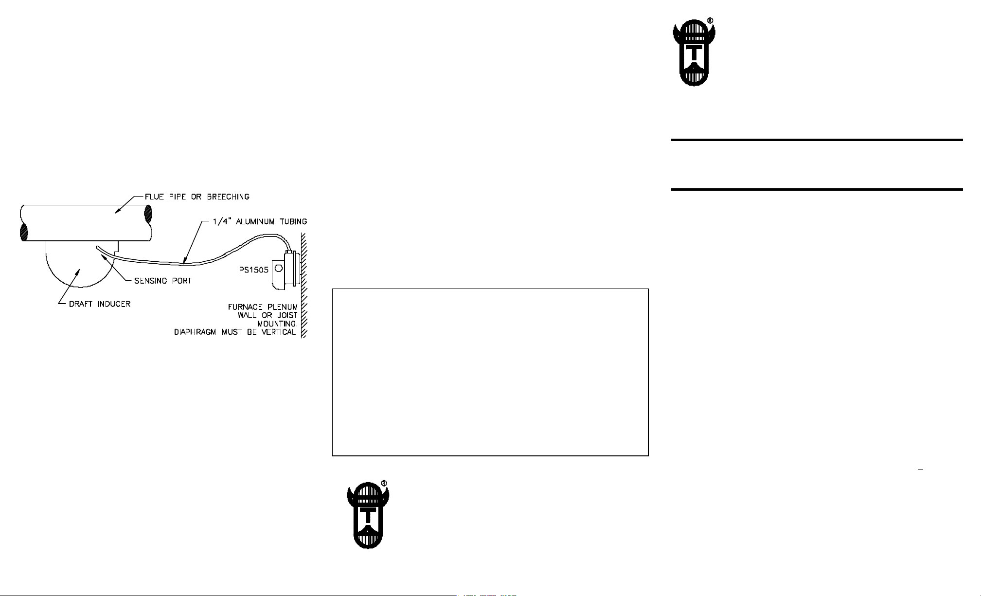
Mounting:
1. Locate holes to be drilled using prover mounting foot as guide.
2. Drill two (2) 1/8” holes.
3. Use sheet metal screws enclosed to mount Fan Prover. Diaphragm
must be vertical to ensure proper operation of switch, See Diagram.
4. Remove inducer from duct if previously installed.
5. FOR MODEL D-3 ONLY
The Model D-3 DraftInducers have two pressure sensing location
knockouts. Location “A” should be used when the D-3 Draft Inducer is
mounted on 7” or 8” diameter pipe. Location “B” should be used when
the D-3 Draft Inducer is mounted on 5” or 6” diameter pipe.
6. Remove Draft Inducer sensing port knockout using a blade screwdriver
and a pliers. Push male brass fitting through hole from inside housing
and lock into position with brass hex nut. Tighten nut with wrench.
7. Unroll tubing and cut to desired length, using a tubing cutter or hack
saw to provide squared, finished cuts. Cut ends should be free of any
burrs or foreign material.
8. Slide brass connecting nuts over tubing and tighten brass fittings.
9. See electrical schematic for application which best represents your
system.
10. All wiring must be done in accordance with the NEC and applicable
Tjernlund Products, Inc. warrants its components for one year from date
of installation. This warranty covers defects in material and workmanship.
This warranty does not cover normal maintenance, transportation or
installation charges for replacement parts or any other service calls or
repairs. Products that are tampered with, damaged, installed improperly,
wired incorrectly or defective due to malfunctioning appliances are not
covered under this warranty.
Tjernlund Products, Inc. will issue credit to the original distributor or provide a free part to replace one that becomes defective during the one year
warranty period. If the part is over 18 months old, proof of date of the
installation in the form of the contractor sales / installation receipt is necessary to prove the unit has been in service for under one year. All
receipts should include the date code of the PS1505. This will help prevent possible credit refusal.
If the PS1505 is defective, return it to your Tjernlund distributor for
replacement. If PS1505 date code is older than 18 months you will need
to provide a copy of the original installation receipt to your distributor.
Credit or replacement will only be issued to a Tjernlund distributor after
the defective part has been returned prepaid to Tjernlund.
TJERNLUND LIMITED ONE YEAR WARRANTY
Tjernlund Products, Inc. warrants to the original purchaser of this product that the product will be free
from defects due to faulty material or workmanship for a period of (1) year from the date of original purchase or delivery to the original purchaser, whichever is earlier. Remedies under this warranty are lim ited to repairing or replacing, at our option, any product which shall, within the above stated warranty
period, be returned to Tjernlund Products, Inc. at the address listed below, postage prepaid. THERE
ARE NO WARRANTIES WHICH EXTEND BEYOND THE DESCRIPTION ON THE FACE HEREOF,
AND TJERNLUND PRODUCTS, INC. EXPRESSLY DISCLAIMS LIABILITY FOR INCIDENTAL OR
CONSEQUENTIAL DAMAGES ARISING FROM THE USE OF THIS PRODUCT. THIS WARRANTY IS
IN LIEU OF ALL OTHER EXPRESS WARRANTIES AND NO AGENT IS AUTHORIZED TO ASSUME
FOR US ANY LIABILITY ADDITIONAL TO THOSE SET FORTH IN THIS LIMITED WARRANTY.
IMPLIED WARRANTIES ARE LIMITED TO THE STATED DURATION OF THIS LIMITED WARRANTY.
Some states do not allow limitation on how long an implied warranty lasts, so that limitation may not
apply to you. In addition, some states do not allow the exclusion or limitation of incidental or consequential damages, so that above limitation or exclusion may not apply to you. This warranty gives you
specific legal rights and you may also have other rights which may vary from State to State. Send all
inquiries regarding warranty work to Tjernlund Products, Inc. 1601 9th Street, White Bear Lake, MN
55110-6794. Phone (651) 426-2993 • (800) 255-4208 • Fax (651) 426-9547.
TJERNLUND PRODUCTS, INC.
1601 Ninth Street • White Bear Lake, MN 55110-6794
PHONE (651) 426-2993 • (800) 255-4208 • FAX (651) 426-9547
Visit our web site • www.tjernlund.com
COPYRIGHT © 1997 TJERNLUND PRODUCTS, INC. P/N 8504008 REV. 1 1/97
TJERNLUND PRODUCTS, INC.
1601 Ninth Street • White Bear Lake, MN 55110-6794
PHONE (651) 426-2993 • (800) 255-4208 • FAX (651) 426-9547
Visit our web site • www.tjernlund.com
MODEL PS1505
FAN PROVER SWITCH
OWNERS INSTRUCTIONS
THESE MUST REMAIN WITH EQUIPMENT
DO NOT DESTROY
PURPOSE
The Tjernlund Fan Prover has been designed to monitor the pressure
within the fan housing only. A motor or wheel failure will decrease housing pressure and deactivate the pressure switch, thus preventing combus tion. The Fan Prover is not a safety control designed to ensure proper
draft or to indicate chimney failure. It is the responsibility of the end user
to properly maintain both the combustion equipment and its chimney or
vent. Yearly maintenance and inspection should be conducted by qualified
service personnel. Failure to follow such maintenance and inspection procedures may result in generation of toxic carbon monoxide gas.
SPECIFICATIONS
Voltage: 125VA pilot duty at 24 volts AC
300VA pilot duty at 115 to 277 volts AC
15 amps non-inductive to 277 volts AC
Electric switch: single pole, single throw, normally open, snap acting
contacts
Electric connectors: #6-32 screw terminals with cup washer
Control set point: non-adjustable
Operating pressure: on increasing vacuum pressure rise, .05 + .02”
W.C. with diaphragm in vertical position.
Maximum pressure: 1/2 psi
Operating temperature range: -40 to 190oF.
Operating position: diaphragm mounted vertical
Sample line connector: Integral compression-type with nut and ferrule
suitable for 1/4” O.D. aluminum or copper tubing.
Page 2
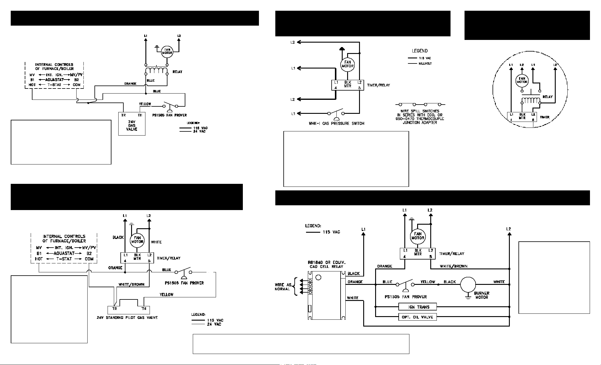
GAS WIRING TO ANY APPLIANCE EQUIPPED WITH 24V CONTROLS
GAS WIRING TO ANY APPLIANCE WITH MILLIVOLT CONTROLS
NO POST-PURGE RELAY/TIMER ON DRAFT INDUCER
REQUIRES POST-PURGE RELAY/TIMER ON DRAFT INDUCER
(DRAFT INDUCER MOTOR LESS THAN 4.4 AMPS)
MODELS I, IL, XL MUST USE 950-0483 ISOLATION RELAY
RELAY/TIMER ISOLATION RELAY WIRING
DRAFT INDUCER MOTORS
GREATER THAN 4.4 AMPS
INCLUDES MODELS I, IL, XL
COMPONENTS NEEDED:
(1) DRAFT INDUCER
(1) PS1505 FAN PROVER
(1) 24/115V RELAY
USE 950-1040 FOR MODELS DJ3 & D3
USE 950-1016 FOR MODELS I, IL, XL
GAS WIRING TO ANY APPLIANCE EQUIPPED WITH 24V CONTROLS
POST-PURGE RELAY/TIMER ON DRAFT INDUCER
(DRAFT INDUCER MOTOR LESS THAN 4.4 AMPS)
MODELS I, IL, XL MUST USE 950-0483 ISOLATION RELAY
COMPONENTS NEEDED:
(1) DRAFT INDUCER
(1) PS1505 FAN PROVER
(1) 950-1067 RELAY/TIMER
MAXIMUM AMP LOAD
IS 4.4 AMPS
USE ISOLATION RELAY ON
RELAY/TIMER IF MOTOR IS OVER
4.4 AMPS. SEE ISOLATION RELAY
DIAGRAM TOP RIGHT.
COMPONENTS NEEDED:
(1) DRAFT INDUCER
(1) RELAY/TIMER 950-1067
MAXIMUM AMP LOAD IS 4.4 AMPS. USE ISOLATION
RELAY ON RELAY/TIMER IF MOTOR IS OVER 4.4
AMPS. SEE ISOLATION RELAY DIAGRAM TOP RIGHT.
(1) WHK-I KIT
(1) 950-0470 THERMOCOUPLE JUNCTION
ADAPTER (FOR RESIDENTIAL WATER HEATERS ONLY)
DRAFT INDUCER CONNECTED TO OIL BURNER WITH R8184G CONTROLS
(DRAFT INDUCER MOTOR LESS THAN 4.4 AMPS) MODELS I, IL, XL MUST USE 950-0483 ISOLATION RELAY
Note: For further assistance call Tjernlund Products, Inc.
Technical Customer Service Department at 1-800-255-4208.
IF DRAFT INDUCER MOTOR IS OVER 4.4
AMPS, WIRE 950-0483 ISOLATION RELAY
AS SHOWN IN THIS DIAGRAM.
COMPONENTS NEEDED:
(1) DRAFT INDUCER
(1) PS1505 FAN PROVER
(1) 950-1067 RELAY/TIMER
MAXIMUM AMP LOAD IS
4.4 AMPS. USE ISOLATION
RELAY ON RELAY/TIMER IF
MOTOR IS OVER 4.4 AMPS.
SEE ISOLATION RELAY
DIAGRAM TOP RIGHT.
 Loading...