

TJERNLUND 950-0453 PAI-T TIMER-CLOCK KIT 8504045 REV. 1 0597, PAI-T Series, 950-0453 User Manual
Page 1
TJERNLUND PRODUCTS, INC.
1601 Ninth Street • White Bear Lake, MN 55110-6794
PHONE (800) 255-4208 • (651) 426-2993 • FAX (651) 426-9547
Visit our web site • www.tjernlund.com
PAI-T SERIES REPLACEMENT TIMER/CLOCK (P/N 950-0453) INSTALLATION INSTRUCTIONS
OWNERS INSTRUCTIONS
THESE INSTRUCTIONS MUST
REMAIN WITH EQUIPMENT
DO NOT DESTROY
READ INSTRUCTIONS CAREFULLY PRIOR TO INSTALLATION
1. Disconnect electrical power before making wiring connections to prevent electrical shock and equipment damage.
2. When wiring is completed, check all components by running system through its entire heating cycle.
IN-FORCERS with date codes prior to “9705”
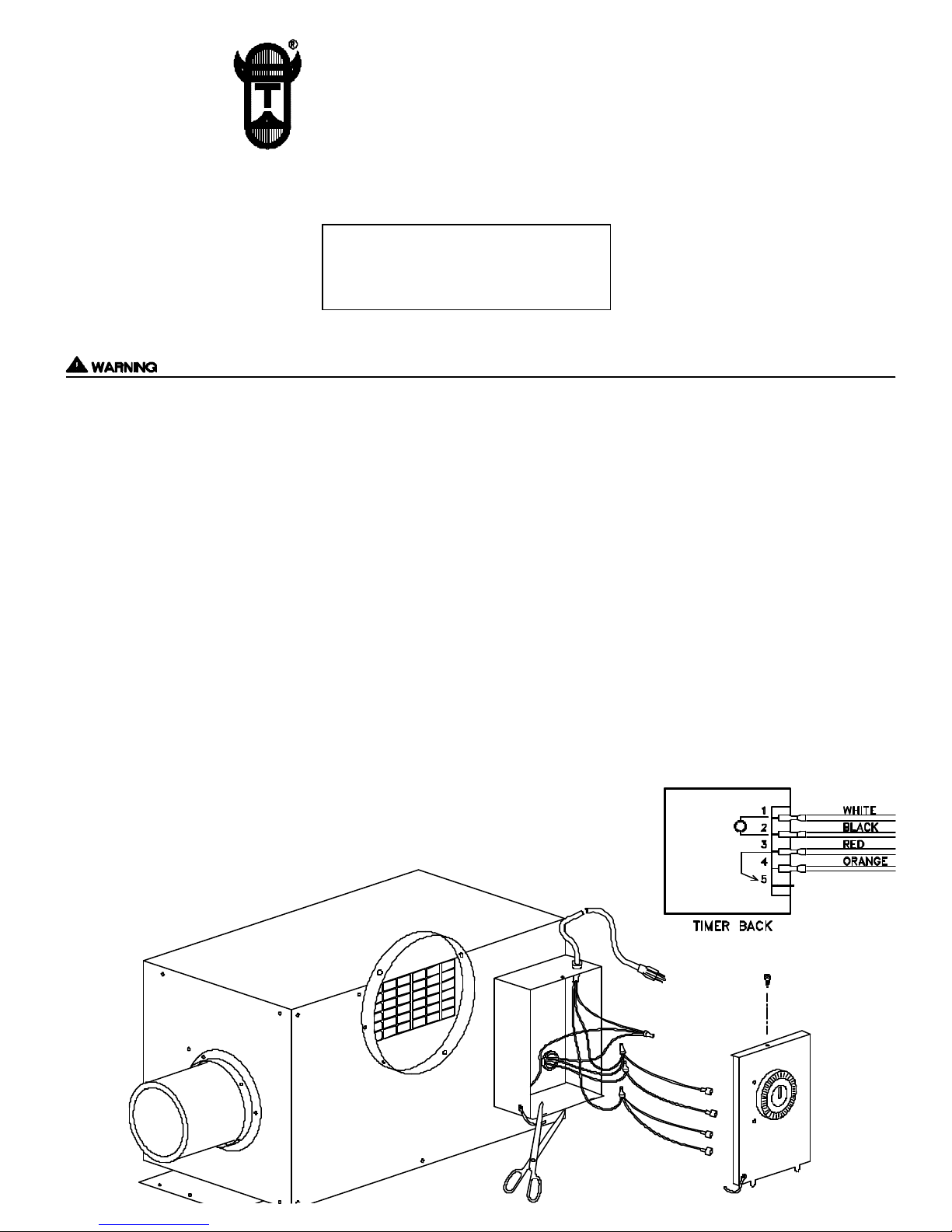
For the steps following below, refer to diagram A.
1. Remove the screw on electrical box cover and remove cover.
2. Disconnect power supply from IN-FORCER and remove 4 wires connected to Timer/Clock.
3. Cut nylon tether which holds cover and Timer/Clock to IN-FORCER.
4. Use 1/8” drill bit to drill out rivet on junction box. Caution: Be careful not to drill into power cord or electrical components.
5. Install new Timer/Clock by screwing tether into junction box using thread rolock 8/32” x 3/8” screw.
6. Connect Black wire to terminal 1 of Timer/Clock.
7. Connect White wire to terminal 2 of Timer/Clock.
8. Connect Red wire to terminal 3 of Timer/Clock.
9. Connect Orange wire to terminal 4 of Timer/Clock.
10. Check for proper operation of IN-FORCER upon reinstallation of Timer/Clock.
DIAGRAM A
Page 2
1. Disconnect electrical power before making wiring connections to prevent electrical shock and equipment damage.
2. When wiring is completed, check all components by running system through its entire heating cycle.
IN-FORCERS with date codes after “9704”
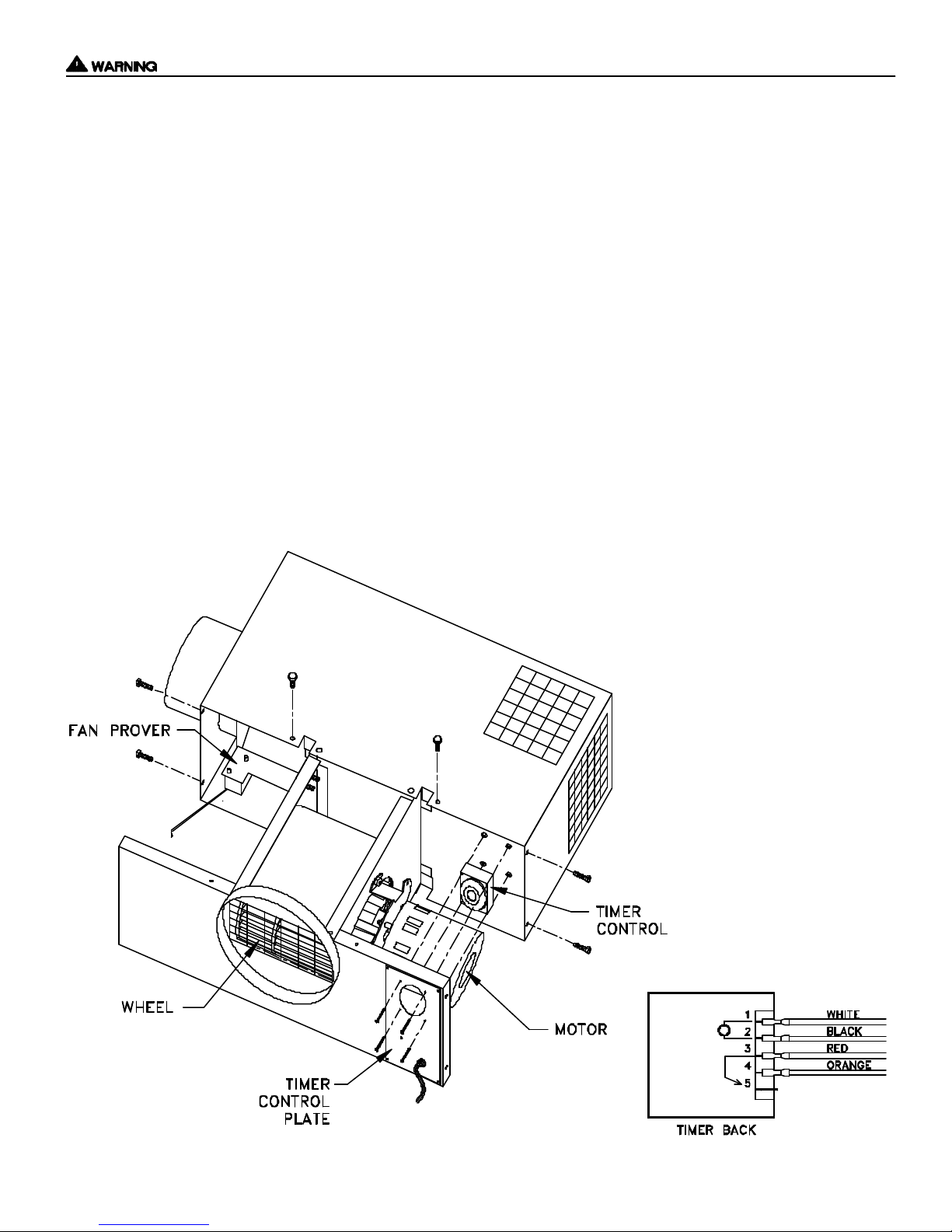
For the steps following below, refer to diagram B.
1. Remove (6) screws from bottom front and sides of IN-FORCER while holding blower assembly firmly.
2. Carefully slide blower assembly down until stops, hold it in place.
3. Carefully remove RED, ORANGE, BLACK and WHITE leads from Timer/Clock. Loosen and remove (2) nuts that
hold Timer/Clock bracket to blower housing and remove Timer/Clock.
4. Remove new Timer/Clock from box and reinstall Timer/Clock to fan housing using (2) nuts provided. Firmly tighten
Timer/Clock onto housing.
5. Push female leads on new Timer/Clock. The ORANGE wire from IN-FORCER should be connected to terminal 4 of
Timer/Clock, RED wire should be connected to terminal 3, BLACK wire to terminal 2, WHITE wire to terminal 1.
6. Follow reverse procedure in steps 1 & 2 to reassemble IN-FORCER. Verify proper heater and IN-FORCER operation.
DIAGRAM B
P/N: 850-4045 ©1997 TJERNLUND PRODUCTS, INC. ALL RIGHTS RESERVED REV. 1 5/97
 Loading...