

Page 1

TJERNLUND PRODUCTS, INC.
1601 Ninth Street • White Bear Lake, MN 55110-6794
PHONE (800) 255-4208 • (651) 426-2993 • FAX (651) 426-9547
Visit our web site • www.tjernlund.com
CPC-2 SOFTWARE VERSION 3.02.02 ADDENDUM
1. New Data Display - | V 0.00 0.00I | Data on this line.
| | Messages on this line.
" " = key pad open; "F" = fault; " " = Inducer is in manual mode
2. New Fault Bandwidth - While the CPC-2 continues to maintain the setpoint pressure
within +/-0.01" w.c., a fault will now occur after the actual pressure is +0.05" w.c. or
-0.02"w.c. away from setpoint for a duration of 90 seconds.
3. New Appliance Staging - Automatically stages appliances for a minimum of 10 seconds
when multiple appliances "call" simultaneously. Pressure must reach and remain within
bandwidth of pressure setpoint for 4 seconds before next appliance is allowed to fire.
4. Control Algorithm Change - The speed of acceleration towards the setpoint (gain) has
been increased to improve the CPC-2 response time. The control architecture will now allow
over shoot into the above setpoint region, resulting in fewer faults.
5. Control Algorithm Change - At start up, the computer program now has continuous
Inducer acceleration towards the setpoint. Originally, the program increased the Inducers
RPMs in four steps. That approach prevented over shooting the setpoint but it took longer to
get there.
6. Restart Function - After a fault the CPC-2 will shut down the appliance(s). After a period
of 60 seconds it will attempt a restart. If fault occurs again, then the CPC-2 will lock the
appliances out until serviced. (Mechanical faults are excluded from restart).
7. Transducer Pressure Range Change - The model TD-2 transducer will now sense
between +0.15" w.c. and -0.60" w.c. This increases the gain when operating at low system
setpoints.
8. Fault Codes Expanded - New fault codes and messages let the service person know what is
wrong and when it happened. The last four faults are automatically stored chronologically.
The fault duration has been expanded to 90 seconds from 60 seconds.
SEE CPC-2 FAULT CODES ON REVERSE SIDE
Page 2

CPC-2 FAULT CODES
FAULT OPERATING OPERATING
CODE MODE STATE FAULT
001 AUTOMATIC IDLE MECHANICAL
011 AUTOMATIC PROVER START -UP MECHANICAL
015 AUTOMATIC PROVER START- UP PROVER
021 AUTOMATIC SYSTEM START-UP MECHANICAL
022 AUTOMATIC SYSTEM START-UP OVER DRAFT
023 AUTOMATIC SYSTEM START-UP UNDER DRAFT
025 AUTOMATIC SYSTEM START-UP PROVER
031 AUTOMATIC PRE-PURGE MECHANICAL
032 AUTOMATIC PRE-PURGE OVER DRAFT
033 AUTOMATIC PRE-PURGE UNDER DRAFT
035 AUTOMATIC PRE-PURGE PROVER
041 AUTOMATIC SYSTEM RUN MECHANICAL
042 AUTOMATIC SYSTEM RUN OVER DRAFT
043 AUTOMATIC SYSTEM RUN UNDER DRAFT
045 AUTOMATIC SYSTEM RUN PROVER
051 AUTOMATIC POST PURGE MECHANICAL
052 AUTOMATIC POST PURGE OVER DRAFT
053 AUTOMATIC POST PURGE UNDER DRAFT
055 AUTOMATIC POST PURGE PROVER
101 MANUAL IDLE MECHANICAL
111 MANUAL PROVER START-UP MECHANICAL
115 MANUAL PROVER START-UP PROVER
131 MANUAL PRE-PURGE MECHANICAL
135 MANUAL PRE-PURGE PROVER
141 MANUAL SYSTEM RUN MECHANICAL
145 MANUAL SYSTEM RUN PROVER
151 MANUAL POST PURGE MECHANICAL
155 MANUAL POST PURGE PROVER
241 VENTER ONLY SYSTEM RUN MECHANICAL
P/N: 8505015 ©2002 TJERNLUND PRODUCTS, INC. ALL RIGHTS RESERVED REV. 1/02
Page 3
REV. A 3/01
TJERNLUND PRODUCTS, INC.
1601 Ninth Street • White Bear Lake, MN 55110-6794
PHONE (800) 255-4208 • (651) 426-2993 • FAX (651) 426-9547
Visit our web site • www.tjernlund.com
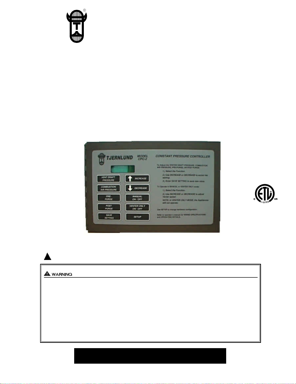
MODEL
CPC-2
CONSTANT PRESSURE CONTROLLER
For Controlling Variable Speed Auto-Draft®Venters, Combustion Air
IN-FORCERTMS, Power Venters and Draft Inducers with multiple appliances
OWNER INSTRUCTIONS, DO NOT DESTROY
!
Recognize this symbol as an indication of important Safety Information!
THESE INSTRUCTIONS ARE INTENDED AS AN AID TO QUALIFIED, LICENSED
SERVICE PERSONNEL FOR PROPER INSTALLATION, ADJUSTMENT AND
OPERATION OF THIS UNIT. READ THESE INSTRUCTIONS THOROUGHLY
BEFORE ATTEMPTING INSTALLATION OR OPERATION. FAILURE TO FOLLOW
THESE INSTRUCTIONS MAY RESULT IN IMPROPER INSTALLATION, ADJUSTMENT, SERVICE OR MAINTENANCE POSSIBLY RESULTING IN FIRE, ELECTRICAL SHOCK, CARBON MONOXIDE POISONING, EXPLOSION, OR PERSONAL
INJURY OR PROPERTY DAMAGE.
PLEASE READ CAREFULLY AND KEEP ON JOB
SITE FOR FUTURE REFERENCE.
Copyright © 2000, Tjernlund Products, Inc. All rights reserved. P/N 8504091
Page 4
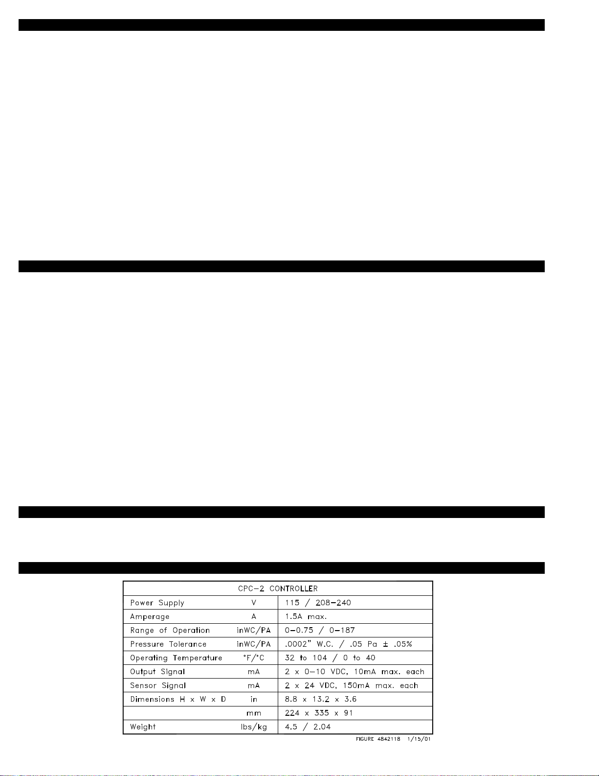
TABLE OF CONTENTS
Page(s)
Description and Operation...............................................................................................................................................1
Specifications ..................................................................................................................................................................1
Cautions ..........................................................................................................................................................................2
Installation of CPC-2, Transducer & Balancing Dampers...............................................................................................2
CPC-2 Circuit Board Features & Circuit Board Layout................................................................................................2-4
Modes of Operation and Programming CPC-2 Controller...........................................................................................5-7
Initial System Power Up and Setup of CPC-2 .............................................................................................................7-9
CPC-2 Fault Messages..............................................................................................................................................9-10
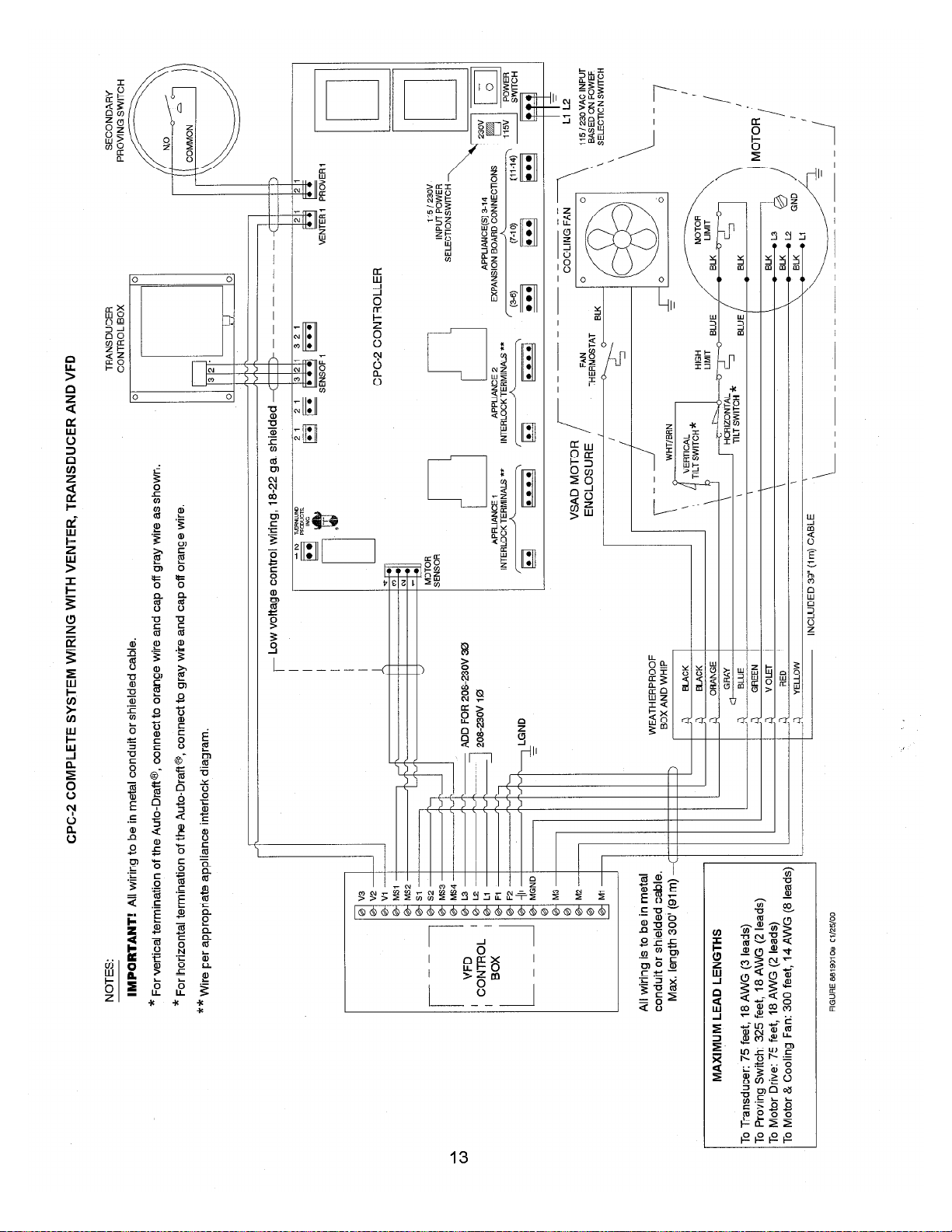
Wiring........................................................................................................................................................................10-13
Replacement Parts & Warranty.....................................................................................................................................14
Tjernlund Products welcomes your comments and questions. Call us at 800-255-4208, Fax 651-426-9547, Email us at
fanmail@tjfans.com or write to: Customer Service, Tjernlund Products, Inc., 1601 Ninth Street, White Bear Lake, MN 55110-6794.
DESCRIPTION AND OPERATION
The CPC-2 controls the motor speed of Tjernlund variable speed Auto-Draft® Venters, Draft Inducers, Power Venters and Combustion
Air In-Forcers. It requires a Pressure Transducer and a Tjernlund Variable Frequency Drive (VFD) to automatically modulate motor
speed. The installer/user may select a pressure set point via the key pad on the CPC-2. The transducer outputs a signal to the CPC-2
proportional to the pressure or draft that it senses. The CPC-2 outputs a proportional signal to the VFD, which modulates the frequency of the voltage to the motor, causing it to speed up or slow down so that the pressure or draft set point is maintained.
Integral to the CPC-2 are two heating appliance interlock circuits. When an appliance calls for heat the burner control signal is intercepted, causing the Auto-Draft® Venter, Draft Inducer, Power Venter or Combustion Air In-Forcer to speed up until the pressure set
point is reached. If the set point is not reached within CPC-2 allowable limits (See Modes of Operation), the interlocked appliance(s)
will not fire.
When a pre-purge time is selected the controller will not allow the appliance(s) to operate until the pressure set point is reached and
the pre-purge time has elapsed. When a post-purge time is selected the appliances are deactivated as soon as the call for heat is
satisfied, but the Auto-Draft® Venter, Draft Inducer, Power Venter or Combustion Air In-Forcer will continue to maintain the pressure
set point until the post-purge time has elapsed. The secondary Fan Prover Switch model PSA-1 is adjusted by the installer to the vent
system draft set point and wires into a terminal strip on the CPC-2. The Transducer in conjunction with the CPC-2 Controller is
considered the primary draft proving control.
The CPC-2 can also be operated in the Manual mode, regulating the motor at a constant, user set speed. The Venter Only mode
allows the user to regulate the motor at a constant, user set speed, but will not allow any interlocked heating appliances to operate.
COMPLETE AUTO-DRAFT® VENT SYSTEM SOLUTIONS
This installation manual does not contain any system design documentation. Installation and use of Auto-Draft® Venters or EXP-4
Appliance Interlock Expansion boards are not covered by this manual. Please refer to those accessory installation manuals.
SPECIFICATIONS
1
Page 5
CAUTIONS
1. Failure to install, maintain and/or operate the CPC-2 in accordance with manufacturer’s instructions may result in conditions that
can produce bodily injury and property damage.
2. The safety interlock and system operation performance checks must be performed on each appliance interlocked with the
CPC-2 in accordance with the Auto-Draft® Venter, IN-FORCER Combustion Air Intake, Power Venter or Draft Inducer installation
instructions.
INSTALLATION AND LOCATION OF CPC-2, TRANSDUCER AND BALANCING DAMPERS
MOUNTING OF THE CPC-2
CPC-2 and transducer should be mounted conveniently inside mechanical
room where access is not restricted. Since set up requires adjustment of
draft settings, close proximity to heating equipment is suggested.
MOUNTING OF THE TRANSDUCER
The transducer must be mounted indoors within six (6) feet of the vent or
chimney transducer sampling tube.
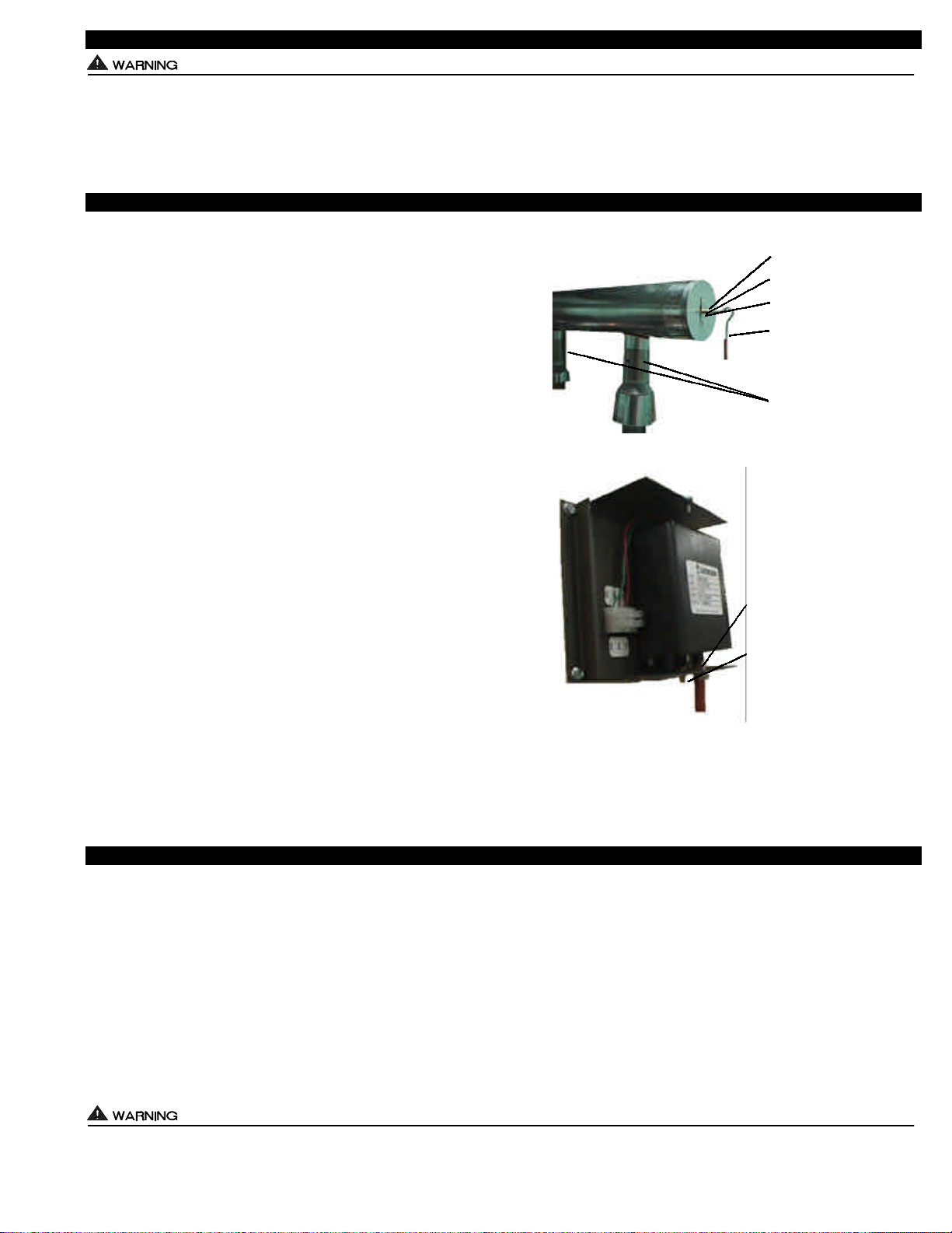
MOUNTING OF TRANSDUCER SAMPLING TUBE
The CPC-2 operates best when the transducer sampling tube measures
static pressure, not velocity pressure. The best position to measure static
pressure is in an extension off of the back end of a horizontal manifold,
(See Diagram A). At this position the probe is not influenced by the velocity of the flue gases being exhausted. Do not use an elbow to connect
the last appliance (furthest from venter) to the common manifold. The
elbow will not allow the sampling tube to measure static pressure. If necessary, “T” off manifold as close to last appliance as possible preferably
using the same diameter pipe as manifold and a clean, burr free transition.
Drill 1/4” sampling hole in vent or chimney for sampling tube. Insert stainless steel sampling tube through 1/4” hole just enough to penetrate interior
of vent pipe and lock in place with compression nut, (See Diagram A).
With the Venter on, a reading with a draft gauge can be used to determine
when interior of pipe has been penetrated.
CONNECTING TRANSDUCER TO SAMPLING TUBE
The transducer - negative pressure front port (closest to cover) is connected to the transducer sampling tube. Make sure the silicone tubing has no
sharp bends or kinks in it. The high pressure rear port (closest to mounting bracket) must be left open to room atmosphere, (See Diagram B).
DIAGRAM A
DIAGRAM B
COMPRESSION NUT
COMPRESSION FERRULE
SAMPLING PORT CENTERED
OVER 1/4” HOLE
1/4” STAINLESS STEEL
SAMPLING TUBE BEND MUST
FACE UPWARDS.
INDIVIDUAL APPLIANCE
BALANCING DAMPERS ARE
NECESSARY. MAKE SURE
THEY DO NOT INTERFERE
WITH FLUE DAMPERS.
FRONT NEGATIVE PRESSURE
PORT CLOSEST TO JUNCTION
BOX COVER MUST BE CONNECTED TO SAMPLING PORT WITH
SILICONE TUBING.
REAR HIGH PRESSURE PORT
CLOSEST TO MOUNTING BRACKET MUST BE LEFT OPEN TO
ROOM ATMOSPHERE.
BALANCING DAMPER INSTALLATION
Balancing dampers are necessary on each appliance vent riser into the common vent manifold. Since the Venter will pull flue gases
from the point of least resistance, those appliances connected closest to the venter will tend to overdraft. Balancing dampers can be
adjusted to match each individual appliance draft requirement, (See Diagram A). Care should be taken so balancing dampers do not
interfere with flue dampers if on equipment. Tjernlund’s ABD-Series (4-10”, 12” & 14” diameter) balancing dampers are constructed
out of 304 stainless steel and feature a tamper proof locking adjustment.
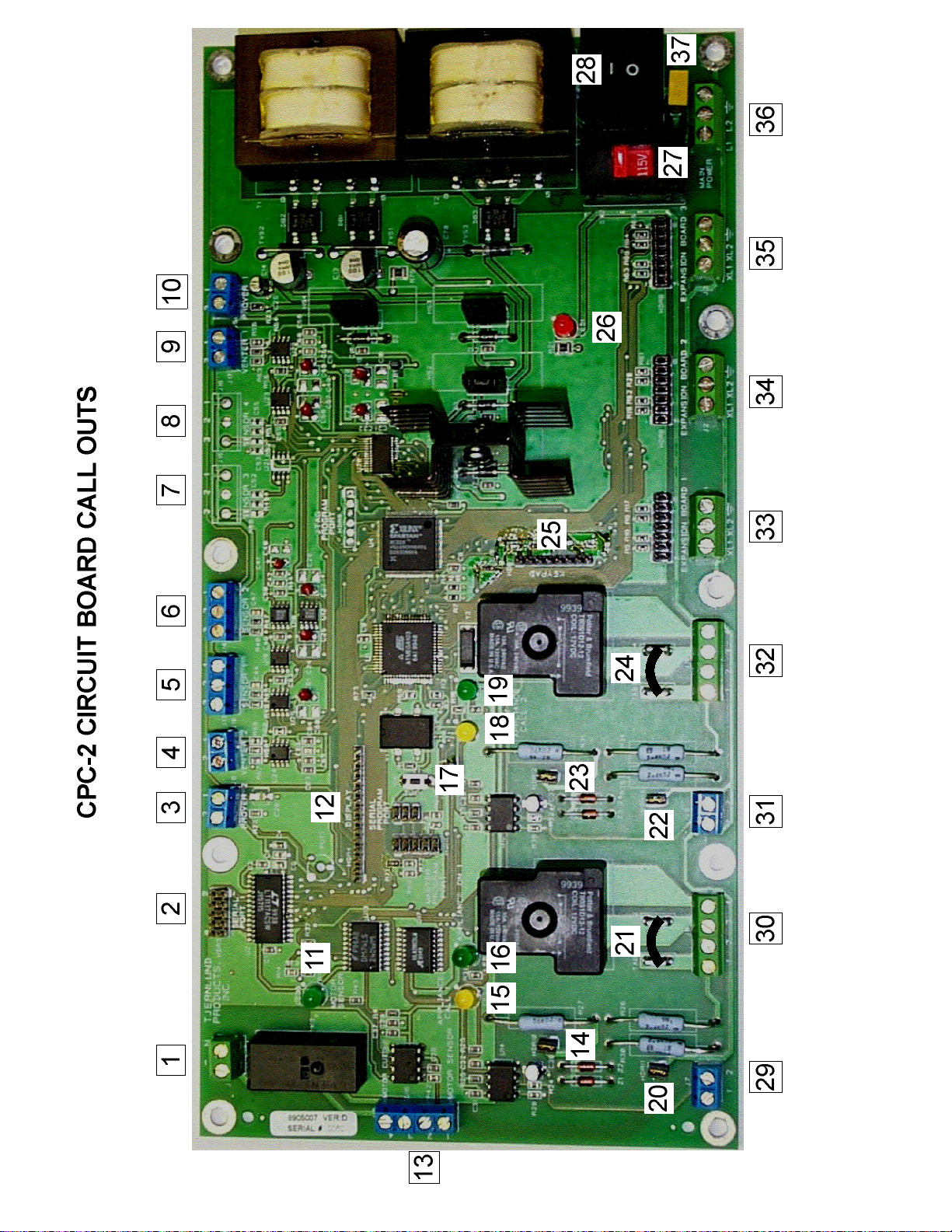
CPC-2 CIRCUIT BOARD FEATURES
Two closed loop channels allowing independent variable speed control of both venting and combustion air systems.
Two appliance interlocks for control circuit voltages between 18 & 240 VAC plus two sets of dry contacts for activation by gas pres-
sure switch or boiler sequencer dry contacts. Additional appliances can be interlocked by using the optional EXP-4 expansion board.
Up to three EXP-4 expansion boards can be connected to interlock up to 14 appliances into a single CPC-2.
Switchable 120/230 VAC 50/60 Hz. fused power supply.
Dry Contact alarm circuit that reacts to motor high limits, tilt switches, prover faults, under pressure conditions.
LED lights displayed for Venter Check circuit, appliance call for heat, prover circuit completed and CPC-2 power supplied to board.
See CPC-2 Circuit Board Call Outs for LED indicator light status.
Serial Port interface.
All sensor connections to the CPC-2 control must only be connected to Tjernlund approved components. Failure to install, maintain
and/or operate the CPC-2 in accordance with manufacturer’s instructions may result in conditions that can produce bodily injury and
property damage.
2
Page 6

CPC-2 CIRCUIT BOARD CALL OUTS
1) ALARM: Dry contacts will close with a Venter Fault or any fault that requires manual resetting. These faults include the Venter,
Start-up, Prover 1 or Prover 2 Faults. Connect to aux. alarm or building mgmt. system. Rated for 1/4 h.p. @ 120 VAC.
2) SERIAL PORT: For inputting future program updates and outputting stored data.
3) PROVER 2: Connection to auxiliary prover for second CPC-2 controlled device. (i.e. Combustion Air In-Forcer or future needs)
4) VENTER 2: Connection to VFD of second CPC-2 controlled device. (i.e. Combustion Air In-Forcer) (0-10 VDC output)
5) SENSOR 1: Connection to vent pressure Transducer to regulate Venter / Inducer speed. (0-10 VDC input)
6) SENSOR 2: Connection to secondary vent pressure Transducer that communicates with CPC-2 to regulate motor speed of
secondary device. (i.e. Combustion Air In-Forcer) (1-12 VDC input)
7) SENSOR 3: Connection to future sensor (open connection, not currently programmed) (0-10 VDC input)
8) SENSOR 4: Connection to future sensor (open connection, not currently programmed) (0-10 VDC input)
9) VENTER 1: Connection to VFD of Venter / Inducer. (1-10 VDC output)
10) PROVER 1: Connection to secondary Fan Prover, i.e. PSA-1 adjustable Fan Prover.
11) MOTOR SENSOR: Green LED indicates that Venter check circuit, i.e. motor limits, housing access limits, high limits, etc.,
are closed and in an acceptable condition.
12) DISPLAY: CPC-2 connection to ribbon cable from display. Ribbon cable printing must face towards top of CPC-2 electrical box.
13) MOTOR SENSOR TERMINAL STRIP: Connects to terminal strip of VFD to lock out interlocked appliances if any motor limit
trips. Relay closes alarm dry contacts (position 1).
14) 18-130 VAC JUMPER TAB: Jumper tab must be removed for 230 VAC interlock with appliance #1.
15) CALL 1: Yellow LED indicates that 1st interlocked appliance is calling for heat.
16) APPLIANCE ON 1: Green LED indicates that vent pressure set point has been reached/maintained and the interlocked
appliance call for heat signal has been delivered to the burner control circuit.
17) RESET BUTTON: Used to soft boot CPC-2 control.
18) CALL 2: Yellow LED indicates that 2nd interlocked appliance is calling for heat.
19) APPLIANCE ON 2: Green LED indicates that vent pressure set point has been reached/maintained and the interlocked
appliance call for heat signal has been delivered to the burner control circuit.
20) DRY CONTACT JUMPER TAB: Jumper tab must be installed if using dry contacts for interlock with appliance #1. Important:
Do not use appliance #1 interlock terminal strip (position 30) if using dry contact actuation.
21) APPLIANCE #1 INTERLOCK JUMPER: Routes intercepted control circuit “hot” voltage from position #1 to position #3, completing
circuit back to appliance through position #4 when all safeties are closed. Normally
kept in place. If removed user can actuate the CPC-2 with one voltage and actuate
the appliance control circuit with another.
22) DRY CONTACT JUMPER TAB: Jumper tab must be installed if using dry contacts for interlock with appliance #2. Important:
Do not use appliance #2 interlock terminal strip (position 32) if using dry contact actuation.
23) 18-130 VAC JUMPER TAB: Jumper tab must be removed for 230 VAC interlock with appliance #2.
24) APPLIANCE #2 INTERLOCK JUMPER: Routes intercepted control circuit “hot” voltage from position #1 to position #3, completing
circuit back to appliance through position #4 when all safeties are closed. Normally
kept in place. If removed user can actuate the CPC-2 with one voltage and actuate
the appliance control circuit with another.
25) KEYPAD: CPC-2 connection to ribbon cable from keypad.
26) SYSTEM POWER LIGHT: Red LED indicates that the CPC-2 has power.
27) VOLTAGE SELECTION SWITCH: Allows the installer to select between 115 VAC and 230 VAC for the main power input to the CPC-2.
28) ON/OFF SWITCH: Turns power to CPC-2 on or off.
29) APPLIANCE #1 DRY CONTACT INTERLOCK TERMINAL: For dry contact actuation of CPC-2. Must install jumper at position 20.
30) APPLIANCE #1 INTERLOCK TERMINAL : Term. 1 & 2: 24 to 230 VAC input, Term. 3 & 4: Contacts rated 1 hp @ 120 VAC.
31) APPLIANCE #2 DRY CONTACT INTERLOCK TERMINAL: For dry contact actuation of CPC-2. Must install jumper at position 21.
32) APPLIANCE #2 INTERLOCK TERMINAL: Term. 1 & 2: 24 to 230 VAC input, Term. 3 & 4: Contacts rated 1 hp @ 120 VAC.
33) EXPANSION BOARD 1: Terminal strip power and ribbon cable interlock connection to optional EXP-4 appliance interlock
expansion board. (Controls appliances 3 - 6)
34) EXPANSION BOARD 2: Terminal strip power and ribbon cable interlock connection to optional EXP-4 appliance interlock
expansion board. (Controls appliances 7 - 10)
35) EXPANSION BOARD 3: Terminal strip power and ribbon cable interlock connection to optional EXP-4 appliance interlock
expansion board. (Controls appliances 11 - 14)
36) MAIN POWER: Primary power connection for CPC-2. May be wired to either 115 VAC single phase or 230 VAC single phase.
Also provides power to any EXP-4 expansion boards connected to CPC-2.
37) CPC-2 MAIN POWER INPUT FUSE: Replaceable 1.5 amp fuse.
PR
3
Page 7
4
Page 8

THE THREE MODES OF OPERATION
OPERATION SEQUENCE IN "AUTOMATIC" MODE:
1. The default mode of operation is Automatic. The first call for heat from any of the interlocked appliances will start the venter and
VENTER START-UP will be displayed on the CPC-2. The CPC-2 ramps up the venter to reach the VENT PRESSURE set point
(V SET x.xx InWc or Pa). This must be accomplished within 60 seconds in the Prover "OFF" mode and 120 seconds in the Prover
"ON" mode. As soon as the Vent Pressure set point is reached the control starts Pre-Purge if this option is activated and displays
the IN PRE-PURGE (V ACT x.xx InWc or Pa) message while continuing to adjust the venter to meet the set point. After Pre-Purge
is timed out, the appliance that called for heat is activated and the message APPLIANCE #__ ON is displayed. If the pre-purge
option is not activated this message will be displayed as soon as the Vent Pressure set point is reached. A Pre-Purge is beneficial
to stabilize vent system pressure prior to burner light off.
2. As other appliances call for heat they are staged 10 seconds apart. If the additional flue gas volume or other pressure disturbance
causes the system pressure to be below the set point for over the 10 second staging period, the appliances are not released to
fire until the set point is reached.
3. Once the last call for heat has been satisfied the CPC-2 starts Post Purge if this option is activated and displays the IN POST
PURGE (V ACT x.xx InWc or Pa) message. During the Post Purge cycle the CPC-2 will continue to maintain the Vent Pressure
set point. Once post purge has timed out, the venter is shut off. If the Post Purge option is not activated the venter will shut off
immediately after the last appliance shuts off.
OPERATION SEQUENCE IN "MANUAL" MODE:
Since the Manual mode operates the venter speed at a fixed user set point care must be taken to verify that the vent system draft is
not so high that it would affect proper appliance burner light off. Cycle appliances individually at the venter speed % selected and verify proper light off. Cycle all connected appliances together to verify that the secondary fan prover closes and no appliances "spill" at
the venter speed % selected. If the venter speed % needed to draft all appliances is too high for proper light off of an individual appliance, disable enough appliances so that the venter speed % is safe in both conditions.
1. The Manual Mode is activated by unlocking the key pad and depressing the MANUAL MODE button once. You can return to
Automatic mode by depressing the MANUAL MODE button any time the key pad is unlocked. The first call for heat from any of
the appliances will start the venter and VENTER START-UP (x% x.xx InWc or Pa) will be displayed on the CPC-2. The CPC-2
ramps up the venter to reach the default venter speed setting of 40%. The secondary fan prover must close within 60 seconds or
a fault will occur. You may adjust the speed setting by depressing the INCREASE or DECREASE buttons. The % speed
selected must be sufficient to make the secondary fan prover or no appliances will be allowed to operate. The CPC-2 will not
allow the venter to operate in the manual mode until the PROVER "ON" mode is activated. If the transducer is operational the
Vent Pressure will be displayed along with the % of venter speed. If the transducer is not operational 0 VENT PRESSURE may
be displayed.
2. Once the secondary fan prover closes, the control starts Pre-Purge if this option is activated and displays the IN PRE-PURGE
message. After Pre-Purge is timed out, the appliance that called for heat is activated and the message APPLIANCE #__ ON is
displayed. If the pre-purge option is not activated this message will be displayed as soon as the % of venter speed setting is
reached.
3. As other appliances call for heat they are staged 10 seconds apart. If the venter speed % is not high enough to keep the
secondary fan prover made as additional appliances fire a PROVER FAULT will occur and the appliances will be shut down.
A "PROVER FAULT" requires a manual reset. See “CPC-2 FAULT MESSAGES” on page 9.
OPERATION SEQUENCE IN "VENTER ONLY" MODE:
1. The Venter Only mode is activated by unlocking the key pad and depressing VENTER ONLY once. In the Venter Only mode the
venter speed can be adjusted but, no interlocked appliances will be allowed to fire.
2. You can adjust the speed setting by depressing the INCREASE or DECREASE buttons. The default speed is 20%.
3. If the Pressure Transducer is operational, the CPC-2 will display the Vent Pressure.
4. You can return to Automatic mode by depressing the VENTER ONLY button again. If the Venter Only mode is not manually
deactivated, the CPC-2 will revert to the Automatic mode after 30 minutes from the last key pressed.
PROGRAMMING THE CPC-2 MODES OF OPERATION
UNLOCKING AND LOCKING THE CPC-2 KEY PAD
To avoid accidental or unauthorized adjustments to the CPC-2 controller a simple access procedure is programmed into the key pad.
To unlock the key pad to make programming changes push (SAVE SETTING) + (SETUP) + (SAVE SETTING) in sequence. This
allows access to enter new controller settings as long as a key is depressed within 60 seconds of the key pad unlock procedure. To
lockout the key pad push (SETUP) scroll to *Lock Out Key Pad* and push (SAVE SETTING).
5
Page 9

LOCKING AND TIMED LOCKOUTS OF THE CPC-2 KEYPAD
The key pad lockout time is 60 seconds from the last key depressed. In Manual mode the key pad will be locked out after 60 seconds and the Venter will stay in manual mode indefinitely unless power is interrupted. When power is interrupted and reestablished
the CPC-2 always starts up in Automatic mode. In Venter Only mode the CPC-2 will revert back to Automatic mode after 45 minutes.
At any time during the programming procedure the key pad can be locked out by depressing the SETUP key, scroll to *LOCK OUT
KEY PAD* and depress SAVE SETTING. IMPORTANT: The key pad must be locked to view System Status and Fault Messages.
USING KEY PAD TO PROGRAM CPC-2
1) Unlock the key pad by depressing (SAVE SETTING) + (SETUP) + (SAVE SETTING) in sequence.
2) Push Key of Desired Mode of Operation.
3) Push ( INCREASE) Or ( DECREASE) to adjust setting. Hold key down to rapidly scroll to set point.
4) Push (SAVE SETTING) key to save new value.
5) Lock out key pad by depressing the (SETUP) key, scroll to *LOCK OUT KEY PAD* and depress (SAVE SETTING).
IMPORTANT: Settings will not be saved unless Save Setting is depressed after each setting change. CPC-2 can be reset to
previously saved programmed settings by by momentarily turning power “off” then “on” again.
SETUP KEY OPTIONS
These options are made via the Setup key.
Viewed on CPC-2 Display
* LOCK OUT *
* KEY PAD *
Locks out the CPC-2 key pad so unintended changes are not made.
RESET SYSTEM
FAULT
SYSTEM VERSION
X.XX.XX
PRESSURE UNITS
In. WC
PASCALS
VENTER PROVER
ON
OFF
COMB. AIR PROVER
PROVER STATE
#1 OPEN or CLSD
#2 OPEN or CLSD
VENTER SENSOR
TD-1
Used to reset CPC-2 Faults that are not self clearing.
Displays CPC-2 Board and software version.
Select either inWC or Pascals.
Enables Secondary Prover 1, i.e. PSA-1. Secondary Prover default setting is “OFF” to allow for initial set up
procedures and PSA-1 Fan Prover Switch Adjustment. Venter Prover must be “ON” after all set ups and
adjustments are completed.
Enables Secondary Prover 2, for Combustion Air System. Default is OFF.
Tells if Prover 1 or Prover 2 contacts are open or closed.
Operating range of TD-1 Transducer for Sensor 1. TD-1 transducer range is from 0.00 to -0.75 inWC.
(0.00 to 187 Pa)
COMB. AIR SENSOR
Transducer for Sensor 2 used for Combustion Air System. Default is NONE.
VENT DRAFT PRESSURE, PRE-PURGE AND POST PURGE KEY OPTIONS
These settings are made via the Vent Draft Pressure, Pre-Purge or Post Purge keys. Used to set vent manifold pressure and
Venter / Inducer post purge and pre-purge settings.
Viewed on CPC-2 Display
SET VENTER PRESS
SET = -X.XX InWC
SET VENTER PRESS
SET = -X.XX Pa
or Sets desired vent manifold pressure read by transducer.
6
Page 10

Viewed on CPC-2 Display
SET PRE-PURGE
XX min. 00 sec.
SET POST PURGE
XX min. 00 sec.
or
Sets optional Venter / Inducer pre and post purge (up to 30 minutes). PrePurge only happens on the 1st appliance call for heat and Post Purge only
happens when the last appliance call for heat is completed.
DEFAULT DISPLAY IN AUTOMATIC MODE OF OPERATION
Display viewed when Venter is operating in automatic mode. Automatic mode is the default mode and is operational when not
running in Manual or Venter Only mode.
Viewed on CPC-2 Display
V SET -X.XX InWC
V ACT -X.XX InWC
V SET -X.XX Pa
V ACT -X.XX Pa
or Displays system set point and actual pressure at sampling point.
DEFAULT DISPLAY IN MANUAL MODE OF OPERATION
Manual Mode will allow system to operate as if you had a manual speed control regulating motor speed. If transducer or pressure
sampling location problems arise vent system can be operated in the Manual Mode at a reduced fixed speed until problem can be
solved. The transducer is ignored in the Manual Mode, but the Secondary Prover, i.e. PSA-1 still interlocks the heating appliances.
NOTE: Secondary Prover Switch to PROVER 1 or PROVER 2 on CPC-2 board is turned off to allow for adjustment and balancing of
vent system draft. The PSA-1 adjustable Fan Prover Switch is set from the factory with the make point at the maximum set point so
manual adjustment of the Fan Prover set point is necessary. After draft set point has been determined, adjust PSA-1 Fan Prover so
that it remains closed at determined vent system draft. Refer to Venter or PSA-1 installation instructions for installation and adjustment of PSA-1 adjustable Fan Prover Switch. IMPORTANT: You must go to Set Up Mode VENTER PROVER and select “ON” to activate Secondary Prover once its set point has been adjusted.
Viewed on CPC-2 Display
MANUAL MODE
XXX% -X.XX InWC
MANUAL MODE
XXX% -X.XX Pa
or
Displays % of motor speed and actual vent pressure at sampling point if
transducer is connected and functioning.
DEFAULT DISPLAY IN VENTER ONLY MODE OF OPERATION
Venter Only Mode is useful to check out the operation of the Venter / Inducer prior to interlock with appliances. Venter Only mode disables all interlocked appliances so they will not operate. Used to verify Venter / Inducer ramps up and down, all vent connections are
tight, Venter impeller operates freely and vent system operates smoothly.
Viewed on CPC-2 Display
VENTER ONLY
XXX% -X.XX InWC
VENTER ONLY
XXX% -X.XX Pa
or Displays % of motor speed and actual pressure at sampling point.
DISPLAYED MESSAGES DURING SYSTEM POWER-UP OF CPC-2
The CPC-2 will start up in Automatic mode and retain all previously saved settings when power is interrupted. The following sequence
will occur when the CPC-2 is initially powered up, any time power is interrupted and reestablished or when the manual reset button on
CPC-2 board is depressed. NOTE: There is approximately a 10 second delay when power is reestablised before the following initialization messages are displayed. The key pad can be unlocked when the initialization process is finished.
CPC-2 CPC -2 CPC-2
CPC-2 CPC -2 CPC-2
INITIALIZING PLEASE WAIT...
SYSTEM VERSION X.XX.XX
Each setting of the CPC-2 will be displayed in the following order.
PRE-PURGE : Displays Pre-Purge time setting (Factory default OFF)
POST PURGE: Displays Post Purge time setting (Factory default OFF)
VENTER SENSOR: Displays operating range of transducer (TD-1 is the only option, operational to -.75” W.C. or -187 Pa)
VENTER PROVER: Displays whether Prover 1, (Venter Fan Prover) is on or off (Factory default OFF)
COMB. AIR PROVER: Displays whether Prover 2, (Combustion Air Prover) is on or off (Factory default OFF)
VENTER: Displays whether exhaust Venter 1 is installed or not installed (Factory default INSTALLED)
COMBUSTION AIR: Displays whether Venter 2 for Combustion Air System is installed (Factory default NOT INSTALLED)
7
Page 11

INITIAL SYSTEM POWER UP AND SET UP OF CPC-2 CONTROLLED VENTING SYSTEM
IMPORTANT: CPC-2 can be reset to previously saved programmed settings by by momentarily turning power “off” then “on” again.
1. Verify that all of the components are installed and the system is wired correctly.
2. Interlock the appliances per the appropriate diagram in the appliance wiring section.
3. Shut off power to each appliance using service disconnect switch(es). Wire complete CPC-2 controlled system per appropriate
diagrams. Establish power to the CPC-2 by turning the power switch on (#28 Circuit Board Call Outs). Establish power to the
VFD by switching on breaker and/or disconnect. In turning the power on to the drive and the controller, the venter and the
expansion boards, if used, will also have power.
4. With the secondary fan prover, i.e. PSA-1 installed, wired and connected to sampling tube, adjust the prover set screw counter
clockwise until it stops. Do not force the setting past the stop.
5. Close all doors and manually operated openings to the mechanical room. Turn on any air removing equipment such as ventilation
fans and other heating appliances not connected to this system.
CONFIRMING PROPER IMPELLER ROTATION
Reference the motor amp draw of the venter model you are installing. This information can be found in the venter installation instructions or on the venter nameplate.
6. Depress DSPL key on the VFD until "IOUT" is lit.
7. Unlock the keypad of the CPC-2 by depressing SAVE SETTING / SETUP/ SAVE SETTING.
8. Depress the VENTER ONLY button on the CPC-2 and then increase the venter speed by depressing the INCREASE button.
As you increase the venter speed take note of the venter amp draw displayed on the VFD. The actual amp draw should not
exceed the nameplate amp draw prior to reaching 100% on the display of the CPC-2. If you reach or exceed the venter amp
rating prior to reaching 100% venter speed, disrupt power to the VFD and switch any two leads to the M1, M2 or M3 terminals
of the VFD terminal strip. Reestablish power to the VFD and repeat this procedure to confirm that the actual motor amp draw is
within the specifications for the venter model installed. NOTE: Inrush amps on initial start-up may exceed nameplate ratings.
9. Turn off the Venter Only option by depressing the VENTER ONLY button.
BALANCING DRAFT OF INDIVIDUAL APPLIANCES
10.Close all balancing dampers and secure in place. The CPC-2 should be in the Automatic mode. The default vent pressure should
read: (V SET -0.15 inWC or V SET 37.4 Pa). Verify that all heating appliance disconnect switch(es) are in the “off” position.
11. Turn appliance disconnect switch “on” and initiate a call for heat on the appliance that is furthest from the venter (or the appliance
that is hardest to vent). The call for heat should activate the venter. When the vent pressure set point is reached the burner should
fire. Open the balancing damper until (-0.03" W.C. or 7.5 Pa) is observed as the draft pressure for the appliance. Measure draft at
the point referenced by the heating appliance manufacturer. If the appliance has a vent damper verify that it has opened.
WARNING: Never allow an appliance to fire if excessive over or under draft pressure is present. If needed, contact the appliance
manufacturer for the light off and operating draft pressure range. Most appliances will safely operate with draft levels between
(-0.01" to -0.06" W.C. or 2.5 to 15 Pa).
12.Turn appliance disconnect switch “on” and initiate a call for heat on the appliance that is next furthest from the venter (or the appliance that is next hardest to vent). Open the balancing damper until (-0.03" W.C. or 7.5 Pa) is measured as the draft pressure for
this appliance. Monitor the draft and adjust the balancing damper as necessary until a steady draft of (-0.03" W.C. or 7.5 Pa) is
maintained.
13.Repeat step 12 for the remaining appliances until they all have had the draft pressure set and are at steady state conditions.
WARNING: An adjustment to any one balancing damper will effect the shared manifold pressure to all. Make sure to keep checking the draft pressure to all of the appliances. Do not allow appliances to shut off during this process. You are setting the system
for the maximum load or demand. All of the appliances tied to this system must be on, running, and at steady state conditions
during this process.
14.If the venter speed reaches 100% before all of the appliances have been fired at steady state conditions, you may need to consider a lower vent pressure set point on the CPC-2 or slightly lower (less draft) draft pressure at each appliance. WARNING: Never
settle for a light off or draft pressure that is outside of the range specified by the appliance manufacturer.
8
Page 12

15.With all of the appliances running and at steady state conditions, confirm the appliance draft pressures. If they all are at acceptable draft pressures, lock the balancing damper’s positions. Confirm the draft pressures at each appliance after the dampers have
been locked in place. Record manifold draft pressure (V SET) reading measured by Transducer and each appliances draft below.
Manifold Pressure (V SET) read by Transducer ______ “W.C. or Pa
Appliance 1 ______ Appliance 5 ______ Appliance 9 ______ Appliance 13 ______
Appliance 2 ______ Appliance 6 ______ Appliance 10 ______ Appliance 14 ______
Appliance 3 ______ Appliance 7 ______ Appliance 11 ______
Appliance 4 ______ Appliance 8 ______ Appliance 12 ______
ACTIVATING & ADJUSTING THE SECONDARY FAN PROVER MODEL PSA-1
16.Unlock the keypad of the CPC-2 by depressing SAVE SETTING / SETUP / SAVE SETTING. When the keypad unlocks depress
the SETUP button. Use the INCREASE or DECREASE buttons to scroll through the setup options until VENTER PROVER is displayed. Activate the venter prover by depressing the SAVE SETTING button. The OFF mode will change to ON. Verify that the
display shows ON. Revert to Automatic mode by depressing the VENT DRAFT PRESSURE button on the keypad. Take note of
the vent pressure set point (V SET) ______. You will have to revert back to this set point after completing the adjustment of the
PSA-1 secondary Fan Prover. Use the DECREASE button to gradually reduce the vent pressure set point until flue gas spillage
occurs or a positive pressure is measured in one of the heating appliance vent risers.
17.Set the secondary fan prover model PSA-1 by carefully turning the adjustment set screw clockwise 1/6 of a turn. Wait 2 seconds.
If the control has not shut all of the appliances off, adjust the set screw another 1/6 of a turn clockwise and wait 2 seconds.
Repeat until the CPC-2 shuts off all of the appliances. Turn the adjustment screw the opposite direction (counter clockwise) ½
turn to avoid nuisance tripping.
18.Remove all of the appliance calls for heat at appliance disconnect. Reset the PROVER #1 FAULT by depressing SETUP and use
the INCREASE or DECREASE buttons to scroll to RESET SYSTEM FAULT. Depress the SAVE SETTING button. If this procedure is correctly performed the message RESET COMPLETE will appear in the CPC-2 display. Depress the VENT DRAFT
PRESSURE button and use the INCREASE button to set the vent pressure back to the original set point (V SET) recorded in step
16. Press SAVE SETTING.
FINAL OPERATION CHECK
19.Reestablish power at each appliance disconnect and activate all of the appliances individually and make sure they light off correctly.
20.Activate all of the appliances together and allow them to reach steady state conditions. Confirm that they all are operating
correctly and have adequate draft pressure.
CPC-2 FAULT MESSAGES
LOCKING AND UNLOCKING THE KEYPAD:
IMPORTANT: The Key pad must be locked to view System Status and Fault Messages.
The keypad can be unlocked by depressing SAVE SETTING / SETUP / SAVE SETTING. The default lockout time is 60 seconds from
the last key depressed. If running in Manual mode the key pad will be locked out 15 minutes after the last key is depressed and stay
in Manual mode. If running in Venter Only mode the key pad remains unlocked and will revert back to Automatic mode and become
locked after 30 minutes. This extended unlocked feature is in an effort to allow the user more time to work within these modes. At
any time during the programming procedure the key pad can be locked out by depressing the SETUP key, scroll to *LOCK OUT KEY
PAD* and depress SAVE SETTING. When the keypad is unlocked, the control will not display faults but it still has control over the
interlocked appliances. If the controller realizes a fault, it will shut off all of the appliances.
VENTER FAULT:
This fault message will be displayed if the control does not see a closed electrical circuit between the J12 1 & 2 terminals (#13 Circuit
Board Call Outs) on the CPC-2 board. This safety circuit may be connected in series with tilt switches, motor enclosure temperature
switches and motor winding high limits. This circuit is continually checked by the CPC-2 regardless of what state it is in. If the CPC-2
has power, it is checking this circuit. When the CPC-2 recognizes this circuit as being open, it will shut off all of the appliances and
shut off the Venter. Resetting this fault can only be accomplished by closing the open circuit. The alarm contacts at J11 1 & 2 terminals (#1 Circuit Board Call Outs) will close when this fault occurs.
START-UP FAULT:
This fault is issued when the system pressure can not reach the pressure set point of the CPC-2 and is driven by the Pressure
Transducer. A 60 second span has been allowed from the first appliance call for heat to the time required for the manifold pressure to
reach the set point. The control confirms this function by comparing the set point in its memory to the pressure measured by the
Pressure Transducer. Possible causes for this fault are extremely long vent pipe runs, a slow performing venter, high pressure set
points, appliance interlock methods, smaller than required venters, bad Transducer or bad pressure sensing location. If the system
experiences this fault, the interlocked appliances will not be allowed to fire. The control will display the START-UP FAULT message
and shut off the venter. The control will need to be reset and the cause for the fault investigated before the control will operate correctly. This fault will only be displayed if the pressure can not be reached on the 1st appliance call.
9
Page 13

Page 14

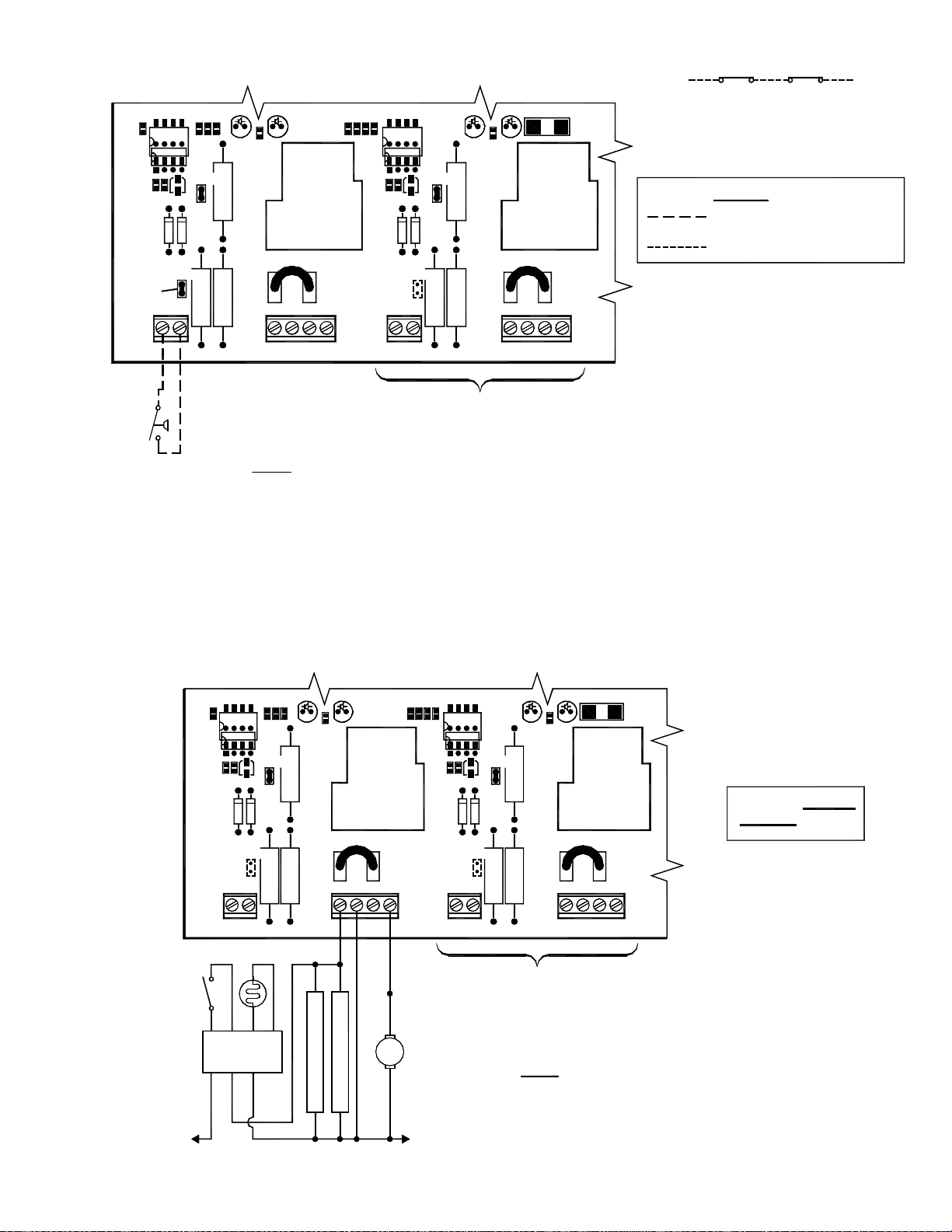
CPC-2 APPLIANCE INTERLOCK WITH 24V GAS APPLIANCES
APPLIANCE INTERLOCK PORTION OF CPC-2 CONTROLLER
HDR10
HDR11
APPL. 1 APPLIANCE 1 APPL. 2 APPLIANCE 2
J7
OF FURNACE/BOILER
INTERNAL CONTROLS
B1
MV
Int. Ign.
Aquastat
B2
MV/PV
HOT
T-stat
COM
J8
J9 J10
3 4
1
2
WIRE PER APPROPRIATE DRY CONTACT
TH
TR
COM HOT
HDR12
HDR13
1 221
APPLIANCE #2 INTERLOCK
OR 18-130 VAC DIAGRAM
NOTES:
DRY CONTACT JUMPER AT (HDR11 OR HDR13) MUST
1.
IMPORTANT:
24V GAS VALVE
BE REMOVED WHEN USING APPLIANCE INTERLOCK TERMINAL STRIP
J8 OR J10.
TERMINAL 3 & 4 CONTACTS ARE RATED FOR 1 HP @ 120 VAC.
2.
CPC-2 APPLIANCE INTERLOCK WITH 115V CONTROLLED APPLIANCES
132
LEGEND:
24 VAC
FIGURE 8819012a 1/17/01
APPLIANCE INTERLOCK
TERMINAL STRIP(S)
4
APPLIANCE INTERLOCK PORTION OF CPC-2 CONTROLLER
HDR10 HDR12
HDR13HDR11
APPL. 1 APPLIANCE 1 APPLIANCE 2APPL. 2
J8J7
1 2 1 2
BURNER MOTOR
RELAY/CONTACTOR
L1
3 4
115V/1/60
J9 J10
21 231
APPLIANCE #2 INTERLOCK
WIRE PER APPROPRIATE DRY CONTACT
BLACK
BURNER
WHITE
L2
OR 18-130 VAC DIAGRAM
MOTOR
NOTES:
1.
IMPORTANT:
DRY CONTACT JUMPER AT (HDR11 OR HDR13) MUST
BE REMOVED WHEN USING APPLIANCE INTERLOCK TERMINAL STRIP
J8 OR J10.
TERMINAL 3 & 4 CONTACTS ARE RATED FOR 1 HP @ 120 VAC.2.
4
FIGURE 8819012b 1/17/01
APPLIANCE INTERLOCK
TERMINAL STRIP(S)
LEGEND:
115 VAC
11
Page 15
CPC-2 DRY CONTACT APPLIANCE INTERLOCK
APPLIANCE INTERLOCK PORTION OF CPC-2 CONTROLLER
WIRE SPILL SWITCHES IN SERIES WITH ECO.
30 MILLIVOLT WATER HEATERS REQUIRE
950-0470 THERMOCOUPLE JUNCTION ADAPTER.
HDR10 HDR12
APPLIANCE
#1 DRY
CONTACT
JUMPER
APPL. 1 APPLIANCE 1 APPLIANCE 2APPL. 2
HDR13HDR11
J7 J8 J9 J10
1 2 21 2 31 4
SWITCH OR
DRY CONTACTS
GAS PRESSURE
NOTES:
1.
3. DO NOT USE APPLIANCE INTERLOCK TERMINAL STRIP J8 OR J10 IF USING DRY CONTACT INTERLOCK FOR THAT APPLIANCE.
31 2 4
APPLIANCE #2 INTERLOCK
WIRE PER APPROPRIATE DRY CONTACT
OR 18-130 VAC DIAGRAM
ONLY APPLIANCES INTERLOCKED INTO THE 18-130 VAC APPLIANCE POSITION (J8 OR J10) WILL RESPOND TO
WARNING:
SYSTEM FAULTS. ANY APPLIANCE WHICH ACTIVATES THE CPC-2 THROUGH THE DRY CONTACT TERMINALS MUST ADD
AUXILIARY SPILL SWITCHES. SPILL SWITCHES MUST BE WIRED INTO APPLIANCE ECO. 30 MILLIVOLT WATER HEATERS
REQUIRE 950-0470 THERMOCOUPLE JUNCTION ADAPTER ALONG WITH SPILL SWITCH(ES).
DRY CONTACT JUMPER MUST BE INSTALLED AT HDR11 OR HDR 13 FOR DRY CONTACT APPLIANCE INTERLOCK.2.
CPC-2 APPLIANCE INTERLOCK WITH OIL-FIRED EQUIPMENT
APPLIANCE INTERLOCK
TERMINAL STRIP(S)
LEGEND:
24 VDC BOARD-GENERATED POWER.
DO NOT SUPPLY POWER!
MILLIVOLT
FIGURE 8819012c 1/17/01
APPLIANCE INTERLOCK PORTION OF CPC-2 CONTROLLER
HDR10 HDR12
HDR13HDR11
APPL. 1 APPLIANCE 1 APPLIANCE 2APPL. 2
J7 J8 J9 J10
1 2 1 2 3 4 21 2 31 4
APPLIANCE #2 INTERLOCK
WIRE PER APPROPRIATE DRY CONTACT
OR 18-130 VAC DIAGRAM
THERMOSTAT
T
B
BLACK
L1 OR B1
T
O
WHITE
ORANGE
F
F
W
IGNITION TRANSFORMER
BLACKWHITE
BURNER
OPTIONAL OIL VALVE
MOTOR
L2 OR B2
NOTES:
1.
IMPORTANT: DRY CONTACT JUMPER AT (HDR11 OR HDR13) MUST
BE REMOVED WHEN USING APPLIANCE INTERLOCK TERMINAL STRIP
J8 OR J10.
TERMINAL 3 & 4 CONTACTS ARE RATED FOR 1 HP @ 120 VAC.2.
FIGURE 8819012d 1/17/01
APPLIANCE INTERLOCK
TERMINAL STRIP(S)
LEGEND:
115 VAC
12
Page 16
Page 17

HOW TO OBTAIN SERVICE ASSISTANCE
1. If you have any questions about the CPC-2 Controller or if it requires adjustment, repair or routine maintenance, we suggest that
you contact your installer, contractor or service agency.
2. If you require technical information contact Tjernlund Products, Inc. at 1-800-255-4208.
When contacting Tjernlund Products, Inc., please have the following information available:
1. Model and Lot # of the CPC-2 Controller
2. Name and address of installer and service agency
3. Date of original installation and dates any service work was performed
4. Details of the problem
LIMITED PARTS WARRANTY AND CLAIM PROCEDURE
Tjernlund Products, Inc. offers a two year warranty on the CPC-2 Controller. This warranty covers defects in material and workmanship. This warranty does not cover normal maintenance, transportation or installation charges for replacement parts or any other service calls or repairs. Products that are tampered with, damaged or defective due to malfunctioning appliances are not covered under
this warranty. This warranty DOES NOT cover the complete CPC-2 Controller if it is operative, except for the defective part.
Tjernlund Products, Inc. will issue credit to your CPC-2 provider or provide a free part to replace one that becomes defective during the
two year warranty period. All receipts should include the Lot # of the CPC-2 Controller to ensure that the defective component corresponds with the complete unit. This will help preclude possible credit refusal.
1.) Determine defective component. If unable to determine faulty component, contact your CPC-2 provider or Tjernlund Products
Technical Customer Service Department at 1-800-255-4208 for troubleshooting assistance.
2.) After the faulty component is determined, return it to your CPC-2 provider for replacement. Please include CPC-2 Lot #
component was taken from. Credit or replacement will only be issued to your CPC-2 provider after the defective part has
been returned prepaid to Tjernlund.
REPLACEMENT PARTS COVERED BY WARRANTY
CPC-2 CIRCUIT BOARD KIT 950-8800
WHAT IS NOT COVERED
Product installed contrary to our installation instructions
Product that has been altered, neglected or misused
Product that has been wired incorrectly
Product that has been damaged by a malfunctioning or mistuned burner
Any freight charges related to the return of the defective part
Any labor charges related to evaluating and replacing the defective part
TJERNLUND LIMITED TWO YEAR WARRANTY
Tjernlund Products, Inc. warrants to the original purchaser of this product that the product will be free from mechanical defects due to faulty material or workmanship for a period of (2) years from the date of original purchase or delivery to the original purchaser, whichever is earlier. Remedies under this warranty are limited to repairing or replacing, at our option, any product which shall, within the above stated warranty period, be returned to Tjernlund Products, Inc. at the address
listed below, postage prepaid. THERE ARE NO WARRANTIES WHICH EXTEND BEYOND THE DESCRIPTION ON THE FACE HEREOF, AND TJERNLUND
PRODUCTS, INC. EXPRESSLY DISCLAIMS LIABILITY FOR INCIDENTAL OR CONSEQUENTIAL DAMAGES ARISING FROM THE USE OF THIS PRODUCT.
THIS WARRANTY IS IN LIEU OF ALL OTHER EXPRESS WARRANTIES AND NO AGENT IS AUTHORIZED TO ASSUME FOR US ANY LIABILITY ADDITIONAL TO THOSE SET FORTH IN THIS LIMITED WARRANTY. IMPLIED WARRANTIES ARE LIMITED TO THE STATED DURATION OF THIS LIMITED WARRANTY. Some states do not allow limitation on how long an implied warranty lasts, so that limitation may not apply to you. In addition, some states do not allow
the exclusion or limitation of incidental or consequential damages, so that above limitation or exclusion may not apply to you. This warranty gives you specific legal
rights and you may also have other rights which may vary from State to State. Send all inquiries regarding warranty work to Tjernlund Products, Inc. 1601 9th
Street, White Bear Lake, MN 55110-6794. Phone (651) 426-2993 • (800) 255-4208 • Fax (651) 426-9547 or email us at fanmail@tjfans.com.
14
 Loading...