

Page 1
Copyright © 2017, Tjernlund Products, Inc. All rights reserved P/N 8504208
OWNER INSTRUCTIONS, DO NOT DESTROY
Recognize this symbol as an indication of important Safety Information!
THESE INSTRUCTIONS ARE INTENDED AS AN AID TO QUALIFIED, LICENSED
SERVICE PERSONNEL FOR PROPER INSTALLATION, ADJUSTMENT AND
OPERATION OF THIS PRODUCT. READ THESE INSTRUCTIONS THOROUGHLY
BEFORE ATTEMPTING INSTALLATION OR OPERATION. FAILURE TO FOLLOW
THESE INSTRUCTIONS MAY RESULT IN IMPROPER INSTALLATION, ADJUSTMENT, SERVICE OR MAINTENANCE POSSIBLY RESULTING IN FIRE, ELECTRICAL SHOCK, CARBON MONOXIDE POISONING, EXPLOSION, PERSONAL
INJURY OR PROPERTY DAMAGE.
!
WARNING
!
DO NOT DESTROY. PLEASE READ CAREFULLY AND
KEEP IN A SAFE PLACE FOR FUTURE REFERENCE.
MODEL COP2 (For RT-Series Inducers)
MODEL COP2DB (For CDB8 Dryer Duct Booster
®
)
(Includes COP Control and Transducer)
INSTALLATION INSTRUCTIONS
REV A 0417
TJERNLUND PRODUCTS, INC.
1601 Ninth Street • White Bear Lake, MN 55110-6794
PHONE (800) 255-4208 • (651) 426-2993 • FAX (651) 426-9547
Visit our web site • www.tjernlund.com
Page 2

1
TABLE OF CONTENTS
Page (s)
Description and General Information...............................................................................................................................1
Installation Restrictions and Cautions ............................................................................................................................1
Selecting the proper commercial Dryer Duct Booster duct size ......................................................................................2
COP Installation ..............................................................................................................................................................3
Sensing Sampling Tube Location & Installation ...........................................................................................................3-5
Wiring Connections between COP and RT-Series Rooftop Fan or CDB8 Dryer Booster Fan.....................................5-7
Adjusting The Pressure (Exhaust) Set Point & Balancing Individual Connections..........................................................8
Adjustment of Balancing Baffle(s) For Kitchen and Bath Fans .......................................................................................9
Operation Overview ........................................................................................................................................................9
Troubleshooting, Service and Warranty ..................................................................................................................10, 11
Tjernlund Products welcomes your comments and questions. Address all correspondence to:
Customer Service • Tjernlund Products, Inc. • 1601 Ninth Street • White Bear Lake, MN 55110-6794
Call us toll free at 800-255-4208, visit our web site @ www.tjernlund.com or email us at fanmail@tjfans.com.
DESCRIPTION
The COP Constant Operating Pressure Control includes a VFD that will modulate the speed of an approved Tjernlund Exhaust
Fan to maintain a user adjustable negative pressure set point. The set point is adjusted through dip switches mounted on the COP
circuit board. The operating range of the COP control is -0.05” W.C. to -0.53” W.C. in 0.01” W.C. increments.
Pressure is measured in a chase, duct or vent at the farthest point from the Exhaust Fan with the pressure transducer and sensing
tube kit. As exhaust volume increases within the duct/chase/vent the resulting reduction in measured pressure causes the COP
control VFD to speed the fan up to handle the additional exhaust volume and slow the fan down when the exhaust volume is
reduced to maintain a constant exhaust pressure.
GENERAL INFORMATION
Each COP is electrically factory line tested before shipment.
After opening carton, inspect thoroughly for hidden damage. If any damage is found notify freight carrier and your distributor immediately and file a concealed damage claim.
INSTALLATION RESTRICTIONS
1. Do not use the COP2 with gas or oil fired heating equipment without interlocking all burners being served with a CIC1 Interlock
Control and the required number of MAC-Series Multiple Appliance Controls. The interlock feature is not activated unless a
jumper is installed between “A” and “GND” of the COP2 operational mode terminal strip. Follow instructions and wiring diagrams included with the CIC1 Interlock Control and perform operation check to validate the interface with the COP2 Control.
2. The COP is intended for indoor installation only. Do not mount the COP on a heat source or in an environment that exceeds
104oF (40oC).
3. The maximum distance wire can be ran from the COP Control to Exhaust Fan Motor is 100 feet.
The maximum distance wire can be ran from the COP Control to Pressure Transducer is 250 feet. Transducer wiring
should be in metal conduit or utilize shielded cable.
CAUTIONS
The COP must be installed by a qualified installer (an individual properly licensed and/or trained) in accordance with all local codes
or, in their absence, in accordance with the National Electrical Code. Failure to install, maintain and/or operate the COP in accordance with manufacturer's instructions may result in conditions which can produce bodily injury and property damage.
1. Disconnect power supply from the COP when making wiring connections and servicing the COP. Failure to do so may result
in personal injury and/or equipment damage.
2. All installation restrictions and instructions in the Tjernlund Exaust Fan installation instructions must be followed when using the COP.
3. Make certain power source is adequate for the COP and Tjernlund Exhaust Fan requirements. Do not add equipment to a circuit
when the total electrical load is unknown.
Page 3
2
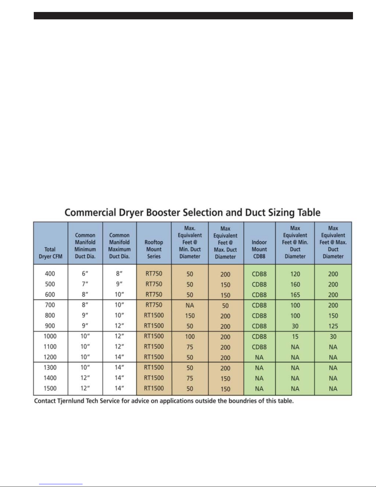
SELECTING THE PROPER COMMERCIAL DRYER DUCT BOOSTER DUCT SIZE
Dryers operate most efficiently when exhaust velocities between 1200-2200 feet-per-minute (FPM) are maintained. The number of
co-ducted dryers operating, exhaust fan model selection and the diameter and length of the common exhaust duct can dramatically affect exhaust velocity. Follow the recommendations below to maximize the efficiency of the Tjernlund exhaust system and
connected dryers.
Over sizing the exhaust manifold will reduce velocities and allow more opportunity for lint to drop out of the exhaust stream.
Undersized or excessively long exhaust manifolds will increase drying time and operating costs. COP controller set point adjustments will allow velocities to be fine tuned.
Common exhaust manifold sizing and Dryer Booster Fan selection
1. Based on the CFM total for all connected dryers find the Total Dryer CFM value in the left column of the table equal to or
greater than that CFM and determine the common manifold minimum or maximum duct diameter.
2. Trace to the right to select the Dryer Booster and determine the maximum equivalent length of common duct based upon your
choice of either the minimum or maximum duct diameter.
Example:
4 Dryers @ 225 CFM/ea.
4 x 225 = 900 Total Dryer CFM
Minimum duct diameter at 900 CFM is 9 inches
Maximum duct diameter at 900 CFM is 12 inches
Installing a common duct sized between 9” and 12” is the optimal size range for maintaining a proper velocity across all operating
conditions. Trace to the right to select the desired Dryer Booster and maximum equivalent feet of common duct based on your
duct diameter choice.
Important Common Manifold Construction Recommendations
Always install a capped length of straight pipe at least 1 pipe diameter long behind the dryer farthest from the exhaust termination
for a stable place to measure exhaust pressure. Always connect individual dryers to the common manifold using wye connectors
pointed towards the exhaust termination. Do not use straight tee connections.
Page 4

3
COP INSTALLATION
The COP is intended for indoor installation only. Do not mount the COP on a heat source or in an environment that exceeds
104oF (40oC). Examples of improper mounting surfaces include vent pipe, top of heater casing or any place where radiant or
convective heat would cause the junction box temperature to exceed temperature limits.
Using the key hole slots on the back of the COP junction box as a template, mark (4) holes on the mounting surface, drill 1/4” pilot
holes for wall anchors if necessary, and secure junction box using provided screws.
PRESS
URE SENSING TUBE LOCATION
PRESSURE SENSING TUBE LOCATION
MULTIPLE DRYERS JOINED IN A COMMON HORIZONTAL DUCT
The sensing tube should be installed in the vent cap of a tee or at the rear of a common exhaust manifold, in back of the vent connector that is farthest from the Dryer Exhaust Fan. The tee is necessary so that only static pressure is measured, (See Diagram
A). If the pressure sensing tube is installed in the side of a duct it will also measure velocity pressure, giving an incorrect signal
back to the COP Control. If mounting on the side of the duct is unavoidable, the sensing tube should be flush to the interior wall of
the duct. Avoid sampling near or in elbows. Duct connections should be sealed to prevent leakage or entrainment. Installer must
provide access for lint clean out.
BEHIND THE DRYER FURTHEST FROM INDUCER
BE LOCATED TWICE THE MANIFOLD DIAMETER
IF POSSIBLE, THE SENSING TUBE SHOULD
D
2D
DRYER FURTHEST
FROM THE INDUCER
MINIMUM
XCOP1
SENSING
TUBING TO
DIAGRAM A
Dryers Common Vented Vertically with CDB8 & COP2DB
Dryers Common Vented Through Side Wall with CDB8 & COP2DB
DRYER FURTHEST
FROM EXHAUST FAN
IF POSSIBLE, THE SENSING TUBE SHOULD
BE LOCATED ONE MAINIFOLD PIPE DIAMETER
BEHIND THE DRYER FURTHEST FROM INDUCER
SENSING
TUBING TO
TRANSDUCER
1 D
MINIMUM
Page 5

4
SENSING TUBE INSTALLATION
DIAGRAM B
MULTIPLE DRYERS, KITCHEN OR BATH FANS
EXHAUSTED INTO A COMMON VERTICAL
CHASE
The sensing tube should be installed to sample the
chase pressure at a point below the lowest duct
connection but above any point in the clean out that
may accumulate moisture or lint. If sampling pressure in the side of a chase, the sensing tube end
should be flush to the interior wall of the chase,
(See Diagram B). Duct connections should be
sealed to prevent leakage or entrainment of air.
Installer must provide access for lint clean out.
Chase Exhaust for Kitchens & Baths or Dryers with RT-Series & COP2
Dryers Common Vented Vertically with RT-Series Inducer & COP2
Page 6

PRESSURE SENSING TUBE INSTALLATION
1. Follow sensing tube location recommendations on pages 3-4.
Use a sharp drill bit to reduce burr, drill a 1/4" hole for pressure
sensing tube. Screw sensing tube bracket to duct/chase with
sampling hole centered, (See Diagram C).
2. Insert stainless steel sensing tube through 1/4" hole enough to
just penetrate interior of duct/chase and lock in place with
compression ferrule and nut, (See Diagram C).
PRESSURE TRANSDUCER MOUNTING AND TUBING CONECTION
Using the key hole slots on the back of the Pressure Transducer junction box
as a template, mark (2) holes on the mounting surface, drill 1/4” pilot holes for
wall anchors if necessary, and secure junction box using provided screws.
Using the included flexible tubing connect the sensing tube to the barbed port
on the exterior of the Pressure Transducer junction box. Excessive additional
lengths of tubing will delay the response of the VFD which can lead to control
lag, (See Diagram D).
SYSTEM TEST PROCEDURE
If using COP2 with RT-Series in conjunction with oil or gas fired heating
equipment, follow the interlock test procedure outlined within the CIC1
installation instructions.
After wiring is complete with supply power switched on and the COP
activation RUN terminals C1 & C2 closed with a switch or jumper, the
Exhaust Fan will run. The fan should operate and maintain the factory set
point of -0.10” W.C. Disconnect the sensing tube from the barbed fitting
on the Transducer electrical box. The fan should ramp to full speed.
Reconnect the tube. The fan should slow down to the original speed.
This change in fan performance can be demonstrated by viewing a draft
gauge that is teed into the tubing from the Pressure Transducer, (See
Diagram E). Draft gauge should be connected as close as possible to
COP Transducer to achieve a reading on draft gauge similar to COP
Transducer.
WIRING
The COP must be wired by a qualified installer (an individual properly licensed and/or trained) in accordance with these instructions and in accordance with all local codes or in their absence, with the current editions of NFPA 70, National Electrical Code in
the U.S. or CSA C22.1-12 Canadian Electrical Code in Canada.
All wiring from the COP to the Dryer Exhaust Fan junction box must be appropriate Class 1 wiring as follows: installed in rigid
metal conduit, intermediate metal conduit, rigid non-metallic conduit, electrical metallic tubing, Type MI Cable, Type MC Cable, or
be otherwise suitably protected from physical damage. Transducer wiring should be in metal conduit or utilize shielded cable.
COP Control supply power may be switched through a building management system, pressure switch or other 115 VAC switch.
The maximum distance VFD output power from the COP to Dryer Exhaust Fan Motor is 100 feet. Exceeding this distance can
result in undesirable COP and Exhaust Fan operation and possible damage to both the fan and the control.
The maximum distance control signal wire can be ran from the COP to Pressure Transducer is 250 feet. Exceeding this distance
can result in lower than desired signal strength. Transducer wiring should be in metal conduit or utilize shielded cable. Nonshielded signal wiring can be influenced by outside conditions resulting in undesirable operation of the COP control.
5
DIAGRAM C
1/4” STAINLESS STEEL
SENSING TUBE BEND MUST
FACE UPWARD
COMPRESSION FERRULE
COMPRESSION NUT
SAMPLING PORT CENTERED
OVER 1/4” HOLE
DIAGRAM D
TO PRESSURE SENSING TUBE IN VENT
COMMON MANIFOLD
DIAGRAM E
TO PRESSURE SENSING
TUBE IN VENT COMMON
MANIFOLD
TO DRAFT GAUGE
CONNECT HERE WHEN
USED FOR SETUP OR
IF PERMANENTLY
INSTALLED.
WARNING
!
Page 7

6
IMPORTANT
The capacitor for the RT-Series fan should remain within the junction box of the flexible whip. Do not install within fan motor compartment.
Failure to wire cooling fan as directed voids warranty.
Installer must supply overload and disconnect protection as dictated by local and national codes. Do not use a fused disconnect.
INSTALLING RT-SERIES FAN ELECTRICAL WHIP
The RT series fan is shipped with an Electrical Whip Assembly which is not connected to the fan. Follow these instructions to connect and wire the whip to the fan. Pull the wires out of the fan through the gasketed hole provided on the fan cover of the RT unit
and wire nut the fan leads to the corresponding colored wires on the free end of the whip.
Remove the (2) 8-32 nuts holding the gasket on the electrical access cover of the RT-Series fan. Carefully stuff the wire nutted
connections back into the fan and secure the cover plate and gasket to the fan housing using the nuts removed in the above step.
Firmly tighten the (2) 8-32 nuts until the gasket compresses.
RT-SERIES FAN CONNECTIONS TO COP CONTROL
Secure the junction box on the opposite end of COP whip to the power supply conduit. Wire nut the 5 leads from the COP (Red,
White/Red, Ground, Black and White) to the corresponding colors of the RT-Series Whip. Stuff Wires into 4 x 4 box on whip. Place
provided gasket on 4 x 4 weather tight box opening. Install the 4 x 4 box cover to the j-box and firmly tighten with provided screws
until the gasket compresses.
CDB-SERIES FAN CONNECTIONS TO COP CONTROL
Install metal conduit containing 5 leads, (Red, White/Red, Ground, Black and White) between the COP2DB and CDB8 Fan. Fasten
to CDB8 Leads with wire nuts and connect wires to COP2DB terminal strip as depicted in wiring diagram.
IMPORTANT: Installer must supply overload and disconnect protection. COP Control power may be switched through a building
management system, pressure switch or other 115 VAC switch
Connect 115 VAC supply voltage to L1, N and the ground terminal of the COP right side power terminal strip. Connect Cooling
Fan BLK and WHT terminals of COP right side power terminal strip to the Black and White cooling fan leads of the Exhaust Fan.
Connect Red, WHT/RED stripe & Ground of COP right side power terminal strip the corresponding colored wires of the Exhaust
Fan.
TRANSDUCER CONNECTIONS
Connect the V+, COM and 1-10 V terminal of the COP terminal strip to the corresponding terminals within the j-box of the
Transducer.
ACTIVATION CONNECTIONS
Use any type of dry contact switch to close RUN position C1 to C2 to activate COP. Alternatively, jumper position C1 to C2 for
constant operation.
REMOVING POWER FROM & RESETTING VFD DRIVE
A fault can be reset on the VFD Drive if the call to C1 & C2 RUN terminals is removed and/or the Power Switch to the VFD Board
in lower right of COP box is turned off for a minimum of 1 minute so capacitors can fully discharge. IMPORTANT: Cycling the VFD
Power Swich off/on without at least a minute delay may result in damage to the VFD.
DIAGRAM F
WARNING: This power switch is for the VFD only. 115 VAC to BLK & WHT
from COP to Exhauster cooling fan, 115 VAC to COP VFD cooling fan and
24 VAC power supply to Transducer will still be live! Disconnect main
braker that supplies 115 VAC to L1 & N on COP Control if it is necessary
to disconnect all power in the COP control, (See Diagram F).
Page 8

7
NL1
COP2 SYSTEM WIRING
POWER SUPPLY
115 VAC
GROUND
WHT
BLK
RED
WHT / RED
COOLING FAN
EXHAUSTER
MOTOR
FIGURE
GRY
GRY
VIO
YEL
REDV+
COM
1-10
P2
P1
C2
C1 RED
GRN
WHT
BLK L1
N
WHT
5
1
1
I
N
GRN
WHT
BLK
RED
BLK
U
A
S
H
T
X
E
E
R
GRNGRN
1-10
COM
V+
VIO
YEL
RED
controller
12
3
4
5
678
RED = FAULT
GREEN = OK
FRONT VIEW
TOP VIEW
LED1
LED2
RED = FAULT
GREEN = OK
ZBA
GND
3.3V
ZBA
GND
3.3V
ZBA
GND
3.3V
OPTION 1 OPTION 2 OPTION 3
OFF
ON
DIP SWITCHES
OUT = ON, IN = OFF
ZBA
GND
3.3V
OPTION 4
EXHAUSTER
THERMOSTAT
RED
= LOW VOLTAGE
= 115 VAC
G
N
L
TB6
TB5
LEGEND
PSC OR SP
VFD
ON / OFF
R
TJERNLUND
WARNING
Do not use the COP2 with gas or oil fired heating
equipment without interlocking all burners being
served with a CIC1 Interlock Control and the
required number of MAC-Series Multiple
Appliance Controllers. The interlock feature is not
activated unless a jumper is installed as shown in
OPTION 3 or 4 below.
OPTION 1:
OPTION 2:
OPTION 3:
OPTION 4:
Exhaust Only
Exhaust Only,
Exhaust with CIC1 Interlock
Exhaust with CIC1 Interlock,
No Overdraft Fault
No Overdraft Fault
115 VAC +/- 10%, 47-64 Hz, Single Phase, 8.0 Amps maximum
115 VAC +/- 10%, 0-60 Hz, Single Phase, 0.12 - 6.2 Amps
Over-Temperature and Over-Current Protected.
For use only with approved Tjernlund Products, Inc. model fans. 800.255.4208 www.tjernlund.com
IF APPLICABLE
WHT
BLK
WHT / RED
Terminals.
DO NOT supply
power to them or
damage to the
TRANSDUCER
Output:
Input:
These are Signal
8052082
9-27-16
PART
1303907
VFD will result.
MAX.
LENGTH
MAX.
LENGTH
100 FT.
250 FT.
COP SYSTEM WIRING
6-70
Page 9

8
ADJUSTING THE EXHAUST PRESSURE SET POINT
The pressure set point is adjusted by positioning dip switches 6 - 1 to match the desired setting listed on the Pressure Setpoint
Table below. The factory set point is 0.10” W.C. The dip switches are located on the Red block on the top of the COP circuit board.
A dip switch is ON when pulled OUT towards you. A dip switch is OFF when pushed IN away from you.
CAUTION: Disconnect electrical power to COP L1 & N prior to adjusting dip switch settings.
ACCELERATION SPEED SETTINGS
Dip Switches 7-8 are used to select drive response time. Slow (30 sec) = 7 ON, 8 OFF, Medium (20 sec) = 7 OFF, 8 ON,
Fast (10 sec) = 7 ON, 8 ON,
The Fast (7 ON, 8 ON) acceleration is the factory default. Acceleration adjustment is typically not required unless set points of
greater than 0.30” W.C. are selected or if the vent run is a long length.
654321
-0.05 IN IN OUT OUT OUT OUT
-0.06 IN OUT IN IN IN IN
-0.06 IN OUT IN IN IN IN
-0.07 IN OUT IN IN IN OUT
-0.08 IN OUT IN IN OUT IN
-0.09 IN OUT IN IN OUT OUT
-0.10 IN OUT IN OUT IN IN
-0.11 IN OUT IN OUT IN OUT
-0.12 IN OUT IN OUT OUT IN
-0.13 IN OUT IN OUT OUT OUT
-0.14 IN OUT OUT IN IN IN
-0.15 IN OUT OUT IN IN OUT
-0.16 IN OUT OUT IN OUT IN
-0.17 IN OUT OUT IN OUT OUT
-0.18 IN OUT OUT OUT IN IN
-0.19 IN OUT OUT OUT IN OUT
-0.20 IN OUT OUT OUT OUT IN
-0.21 IN OUT OUT OUT OUT OUT
-0.22 OUT IN IN IN IN IN
-0.23 OUT IN IN IN IN OUT
-0.24 OUT IN IN IN OUT IN
-0.25 OUT IN IN IN OUT OUT
-0.26 OUT IN IN OUT IN IN
-0.27 OUT IN IN OUT IN OUT
-0.28 OUT IN IN OUT OUT IN
-0.29 OUT IN IN OUT OUT OUT
-0.30 OUT IN OUT IN IN IN
-0.31 OUT IN OUT IN IN OUT
-0.32 OUT IN OUT IN OUT IN
-0.33 OUT IN OUT IN OUT OUT
-0.34 OUT IN OUT OUT IN IN
-0.35 OUT IN OUT OUT IN OUT
-0.36 OUT IN OUT OUT OUT IN
-0.37 OUT IN OUT OUT OUT OUT
-0.38OUTOUTININININ
-0.39 OUT OUT IN IN IN OUT
-0.40 OUT OUT IN IN OUT IN
-0.41 OUT OUT IN IN OUT OUT
-0.42 OUT OUT IN OUT IN IN
-0.43 OUT OUT IN OUT IN OUT
-0.44 OUT OUT IN OUT OUT IN
-0.45 OUT OUT IN OUT OUT OUT
-0.46 OUT OUT OUT IN IN IN
-0.47 OUT OUT OUT IN IN OUT
-0.48 OUT OUT OUT IN OUT IN
-0.49 OUT OUT OUT IN OUT OUT
-0.50 OUT OUT OUT OUT IN IN
-0.51 OUT OUT OUT OUT IN OUT
-0.52 OUT OUT OUT OUT OUT IN
-0.53 OUT OUT OUT OUT OUT OUT
Pressure Setpoint Table
Output
WC
DIP switch settings
DIP SWITCHES
OUT = ON (Towards You)
IN = OFF (Away from You)
8 7 6 5 4 3 2 1
6 1
Page 10

9
ADJUSTMENT OF BALANCING BAFFLE(S) FOR KITCHEN AND BATH FANS USING COP2 WITH RT-SERIES EXHAUSTER
IMPORTANT: Do Not use Balancing Baffles for dryer applications due to the potential for lint buildup.
1. With all balancing baffles closed and starting with connection at lowest floor drill a small sampling hole in duct connection to
the chase 1 foot behind the Balancing Baffle (opposite side of chase connection).
2. With the COP2 Control, RT-Series Fan and Bath/kitchen fans connected to the duct operating, gradually open the Balancing
Baffle until desired negative exhaust pressure is measured and lock in place. Typically a measurement of a -0.02 to -0.05" W.C.
is adequate.
3. Repeat steps 1 and 2 for each floor, moving up towards the RT-Series Fan.
4. After all are set, review all measurements on each and readjust as needed.
OPERATION OVERVIEW
With 115 VAC supplied to L1 and N and the VFD power switch in the off position the following circuits are powered. The disconnect that powers L1 and N must be switched off to remove power from these circuits:
24 Volt Transformer
Pressure Transducer
BLK and WHT terminals to the thermostat of the Exhauster motor cooling fan
Thermostat for the VFD heat sync cooling fan
When the VFD switch is turned on, the VFD is powered but still must have activation RUN terminals C1 & C2 closed for the
Exhaust Fan to operate.
With the activation circuit closed the COP controller will reference the sampling tube pressure via a 1-10 VDC signal with 2.8 VDC
= 0.00” W.C. As pressure is reduced by additional exhaust volume, winds or interior negative pressures the transducer will output
a lower voltage to the VFD, increase the frequency from the VFD, causing the Exhaust Fan to speed up until the set point pressure
is reached. Further fluctuations in measured pressure will cause the VFD to modulate the frequency to the Exhaust Fan so that the
set point exhaust pressure is maintained.
If the fan cannot maintain the setpoint pressure within ±0.02” W.C. at anytime for more than a 50 second period, the Green LED
on the middle left side of the VFD will turn Red and cause the system to fault. Reset the VFD by turning the on/off switch “Off” for
one minute to reset the fault and cycle the fan to determine if a problem exists. If the set point is low enough to allow natural ventilation to exceed the set point jumper “B” to “GND” on the green logic terminal strip to disable over draft protection. The control will
now only fault for an under draft condition.
TROUBLESHOOTING ELECTRICAL PROBLEMS
It is necessary to measure voltage during troubleshooting. Extreme caution must be exercised to prevent injury. If you are unable
to determine the defective part with the use of this guide, call your Tjernlund distributor or Tjernlund Products direct at
1-800-255-4208 for further assistance.
EXHAUST FAN MOTOR DOES NOT OPERATE
Check that the COP control has power by verifying that the top LED is Green.
If this LED is Red, turn the VFD power switch off for a minimum of 1 minute to reset the fault. A Red status indicates an over-current or circuit board over-temperature issue. In some cases an acceleration rate that is too fast can cause an over-current fault. In
most cases the Exhaust Fan should be checked to verify that the shaft rotates freely with power disrupted. Since the Exhaust Fan
may not operate if the exhaust set point is reached by natural means perform the following test:
Top LED is Green
Verify that the supply power to the COP is switched on and the activation RUN terminals C1 & C2 are closed with a switch or
jumper to start the Exhaust Fan. Disconnect the sensing tube from the barbed fitting on the Transducer electrical box. The fan
should ramp to full speed. Reconnect the tube. The fan should slow down to the original speed. This change in fan performance
can be demonstrated by viewing a draft gauge that is teed into the tubing from the pressure transducer as shown in Diagram E,
Page 5.
If removing the sensing tube does not cause the fan to speed up measure AC voltage at terminals V+ and COM of the Transducer
and look for a reading between 22 - 30 VAC. If voltage in this range is measured remove tube from the barbed connection on the
Transducer and look for between 2.7 - 2.9 VDC when measuring terminals 1-10 and COM.
Page 11

If voltage to and from the Transducer are in the ranges listed above, measure COP VFD output AC voltage at the Red and
WHT/RED stripe terminals with the Transducer tube still disconnected. Look for a reading of around 125 volts AC.
If around 125 VAC is measured check for voltage at the Red and White w/Red stripe leads in the j-box of the Exhaust Fan. If the
referenced voltage is measured check motor capacitor and verify reading of 5µF ± 5%. If the capacitor is within specs look for
around 125 VDC at the Red and White w/Red stripe leads within the motor enclosure. If this voltage range is present, the Exhaust
Fan motor is suspect and may need replacement. Remove and bench test with 115 VAC.
HOW TO OBTAIN SERVICE ASSISTANCE
1. If you have any questions about your COP or if it requires adjustment or repair, contact your installer, contractor or
service agency.
2. If you require technical information contact Tjernlund Products, Inc. at 1-800-255-4208 with the following information.
1. Model of the Exhaust Fan that COP is interlocked with as shown on the Exhaust Fan nameplate.
2. Name and address of installer and any service agency who performed work on the system.
3. Date of original installation and dates any service work was performed.
4. Details of the problem as you can best describe them.
LIMITED PARTS WARRANTY AND CLAIM PROCEDURE
Tjernlund Products, Inc. warrants the components of the COP for one year from date of installation. This warranty covers defects
in material and workmanship. This warranty does not cover normal maintenance, transportation or installation charges for replacement parts or any other service calls or repairs. This warranty DOES NOT cover the complete COP if it is operative, except for the
defective part.
Tjernlund Products, Inc. will issue credit or provide a free part to replace one that becomes defective during the one year warranty
period. Proof of date of the installation in the form of the contractor sales/installation receipt is necessary to prove the unit has
been in service for under one year. All receipts should include the date code of the COP to ensure that the defective component
corresponds with the complete unit. This will help prevent possible credit refusal.
1. Follow troubleshooting guide to determine defective component. If unable to determine faulty component, contact your
Tjernlund distributor or Tjernlund Technical Customer Service at 1-800-255-4208 for troubleshooting assistance.
2. After the faulty component is determined, return it to your Tjernlund distributor for replacement. Please include COP date code
component was taken from. The date code is located on the Electrical Box cover. If the date code is older than one year, you
will need to provide a copy of the original installation receipt to your distributor. Credit or replacement will only be issued to a
Tjernlund distributor after the part has been returned prepaid to Tjernlund and verified defective.
WHAT IS NOT COVERED
Product installed contrary to our installation instructions, altered, neglected or misused
Product that has been wired incorrectly
Any freight charges related to the return of the defective part
Any labor charges related to evaluating and replacing the defective part
REPLACEMENT PARTS
Component Part Number
24 Volt Transformer 950-2030
COP Pressure Transducer 950-9352
Heat Sync Cooling Fan T-Stat 950-8301
Heat Sync Cooling Fan 950-0020
COP2 Heater Interlock Control* CIC1
*NOTE: The CIC1 Accessory Control
is a standard UC1 Control with an
included relay. It is for use with the
COP2 and RT-Series Fans.
10
Page 12

11
TJERNLUND LIMITED ONE YEAR WARRANTY
Tjernlund Products, Inc. warrants to the original purchaser of this product that the product will be free from defects due to faulty material or workmanship for a period of (1) year from the date of original purchase or delivery to the original purchaser, whichever is earlier. Remedies under
this warranty are limited to repairing or replacing, at our option, any product which shall, within the above stated warranty period, be returned to
Tjernlund Products, Inc. at the address listed below, postage prepaid. THERE ARE NO WARRANTIES WHICH EXTEND BEYOND THE
DESCRIPTION ON THE FACE HEREOF, AND TJERNLUND PRODUCTS, INC. EXPRESSLY DISCLAIMS LIABILITY FOR INCIDENTAL OR
CONSEQUENTIAL DAMAGES ARISING FROM THE USE OF THIS PRODUCT. THIS WARRANTY IS IN LIEU OF ALL OTHER EXPRESS
WARRANTIES AND NO AGENT IS AUTHORIZED TO ASSUME FOR US ANY LIABILITY ADDITIONAL TO THOSE SET FORTH IN THIS LIMITED WARRANTY. IMPLIED WARRANTIES ARE LIMITED TO THE STATED DURATION OF THIS LIMITED WARRANTY. Some states do
not allow limitation on how long an implied warranty lasts, so that limitation may not apply to you. In addition, some states do not allow the
exclusion or limitation of incidental or consequential damages, so that above limitation or exclusion may not apply to you. This warranty gives
you specific legal rights and you may also have other rights which may vary from State to State. Send all inquiries regarding warranty work to
Tjernlund Products, Inc. 1601 9th Street, White Bear Lake, MN 55110-6794. Phone (651) 426-2993 • (800) 255-4208 • Fax (651) 426-9547 •
Email fanmail@tjfans.com.
 Loading...