

Page 1
TJERNLUND PRODUCTS, INC.
1601 Ninth Street • White Bear Lake, MN 55110-6794
PHONE (800) 255-4208 • (651) 426-2993 • FAX (651) 426-9547
Visit our web site • www.tjernlund.com
READ OWNERS INSTRUCTIONS CARE-
FULLY PRIOR TO INSTALLATION.
THESE INSTRUCTIONS MUST REMAIN
WITH EQUIPMENT. DO NOT DESTROY.
AIRESHARETMLEVEL TO LEVEL VENTILATOR
MODEL ASLL
©2009 TJERNLUND PRODUCTS, INC. ALL RIGHTS RESERVED P/N: 8504156
DESCRIPTION
The AireShare™ Level to Level Ventilators distribute air from one conditioned space to another. Virtually every home has temperature
differentials on different levels of the house. The AireShare™ moves air from one level of the house to a room on another level of the
house that is uncomfortably hot or cold. This air movement helps to destratify stagnant air in homes, improve ventilation rates and make
both rooms more comfortable.
ASLL SPECIFICATIONS & COMPONENTS
GENERAL INFORMATION
Every Tjernlund AireShare™ Level to Level Ventilator is electrically factory line tested before shipment.
After opening carton, inspect thoroughly for shipping damage. Impeller should rotate freely and all electrical wires and connections
should be secured. If any damage is found, notify freight carrier and your distributor immediately and file a concealed damage claim.
INSTALLATION RESTRICTIONS
The AireShare™ Ventilator must be installed by a qualified installer in accordance with these instructions and all local codes or in their
absence in accordance with the latest editions of the International Residential Code and International Electrical Code. Improper installation can create a hazardous condition such as fire, electric shock or personal injury. To reduce these risks significantly, use this device
only in the manner intended by the manufacturer. If you have questions about proper usage of this device, call Tjernlund Products.
Always disconnect the AireShare™ Ventilator from its power source before installation and servicing.
IMPORTANT: An in depth investigation of the floor joist/truss layout is required prior to installation. Avoid a floor/ceiling cavity that is a
path for plumbing supply lines, drains, vents or ductwork. Also confirm foundation block and upstairs walls do not obstruct installation.
SPECIFICATIONS
Blower: 75 cfm
Motor: 115 Volts ~ 60 Hz
25 Watts ~ 0.50 amps maximum
Impeller: Transtangental, cross-flow
Sound: 42 db (1.15 Sones)
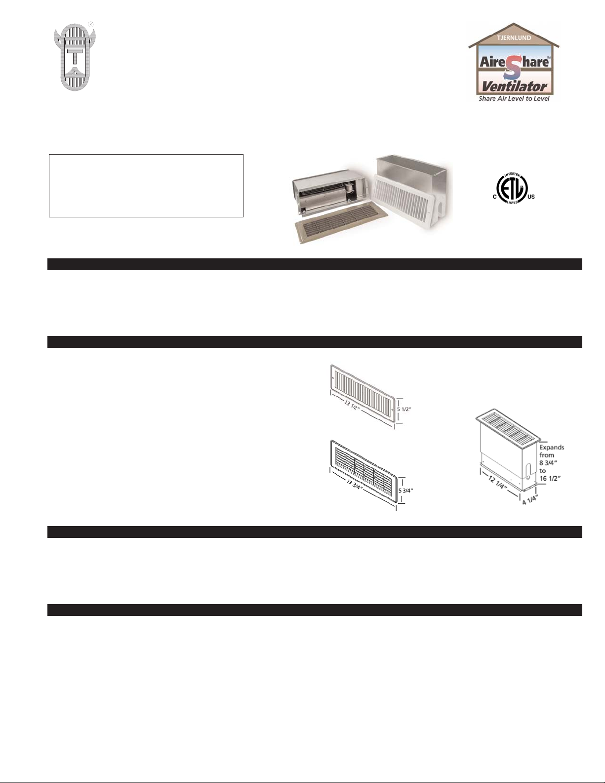
DIMENSIONS:
White Ceiling Grille: 5 1/2” x 13 1/2” (flush)
Brown Floor Grille: 5 3/4” x 13 3/4” (flush)
Blower Housing Rough-in: 4 1/16” x 12 5/16”
Outer Sleeve Rough-In: 4 5/16” x 12 5/16”
Expansion Depth* 8 3/4” to 16 1/2”
(*top of floor to bottom of ceiling)
CEILING GRILLE
FLOOR GRILLE
EXPANSION DEPTH
Page 2
• The AireShare™ may not be used to exhaust hazardous or explosive materials or vapors.
• The AireShare™ may not be used in kitchens or move moisture-laden air from sources such as bathrooms and kitchens.
• The AireShare™ may not be used to move air from from a utility room containing gas or oil fuel heating equipment.
WARNING: Disconnect power to the ASLL before servicing. To reduce the risk of fire, electrical shock and injury to persons, the
AireShare™ must be installed with the ASLL Floor grille that was provided with the ASLL.
WARNING: To reduce the risk of fire or electrical shock, do not use this fan with any solid state speed control devices.
WARNING: To reduce the risk of fire, electric shock, or injury to persons, observe the following:
a. Use this unit only in the manner intended by the manufacturer. If you have questions, contact the manufacturer.
b. Before servicing or cleaning unit, switch power off at service panel and lock the service disconnecting means to prevent power
from being switched on accidentally. When the service disconnecting means cannot be locked, securely fasten a prominent
warning device, such as a tag, to the service panel.
c. Installation work and electrical wiring must be done by qualified person(s) in accordance with all applicable codes and standards,
including fire-rated construction.
d. When cutting or drilling into floor, wall or ceiling areas, do not damage electrical wiring and other hidden utilities.
Disrupt power at circuit breaker to outlets near the joist/truss area you will be working in.
When sawing through sheetrock or floor, immediately stop if you detect the saw blade coming in contact
with any wiring or plumbing. Investigate further to determine if it is possible to safely continue to use this
joist/truss cavity. Switch to another joist/truss cavity if necessary.
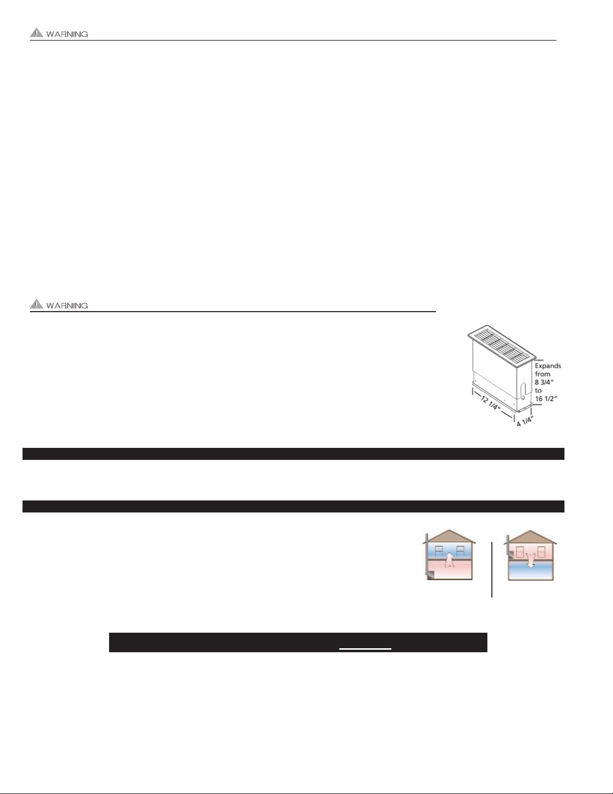
BEFORE YOU START:
Determine the joist/truss cavity mounting location. If you are wiring to an existing outlet it is best to select a
joist/truss section that contains an electrical outlet for wiring. IMPORTANT: Direction of joist/truss might
determine which direction the ASLL can be installed. Review ASLL dimensions and minimum and
maximum expansion of sleeve before installing, (See Diagram A). Use a stud finder to verify joist/truss
location and direction.
TOOLS REQUIRED
Sheetrock Saw • Phillips Screwdriver • Drill • Tape Measure • Utility Knife • Wire Stripper • Stud Finder (required if ceiling is finished)
3/8” drill bit & 1/4” drill bit 2” longer than joist/truss thickness (long bit not required if ceiling is unfinished) • Jig Saw / Reciprocating Saw
INSTALLATION
PRE-INSTALLATION INSPECTION
IMPORTANT: An in depth investigation of the floor joist/truss layout is required prior to installa-
tion. Avoid a section that is a path for plumbing supply lines, drains, vents or ductwork. Also confirm foundation block or upstairs walls do not obstruct installation. If wiring to an existing outlet
using surface wiring, it is best to select a joist/truss section that contains an electrical outlet to
wire into.
Determine if the installation is a downflow or upflow application. If ASLL will discharge air up to
the level above it is upflow. If ASLL will discharge air down to a lower level it is downflow.
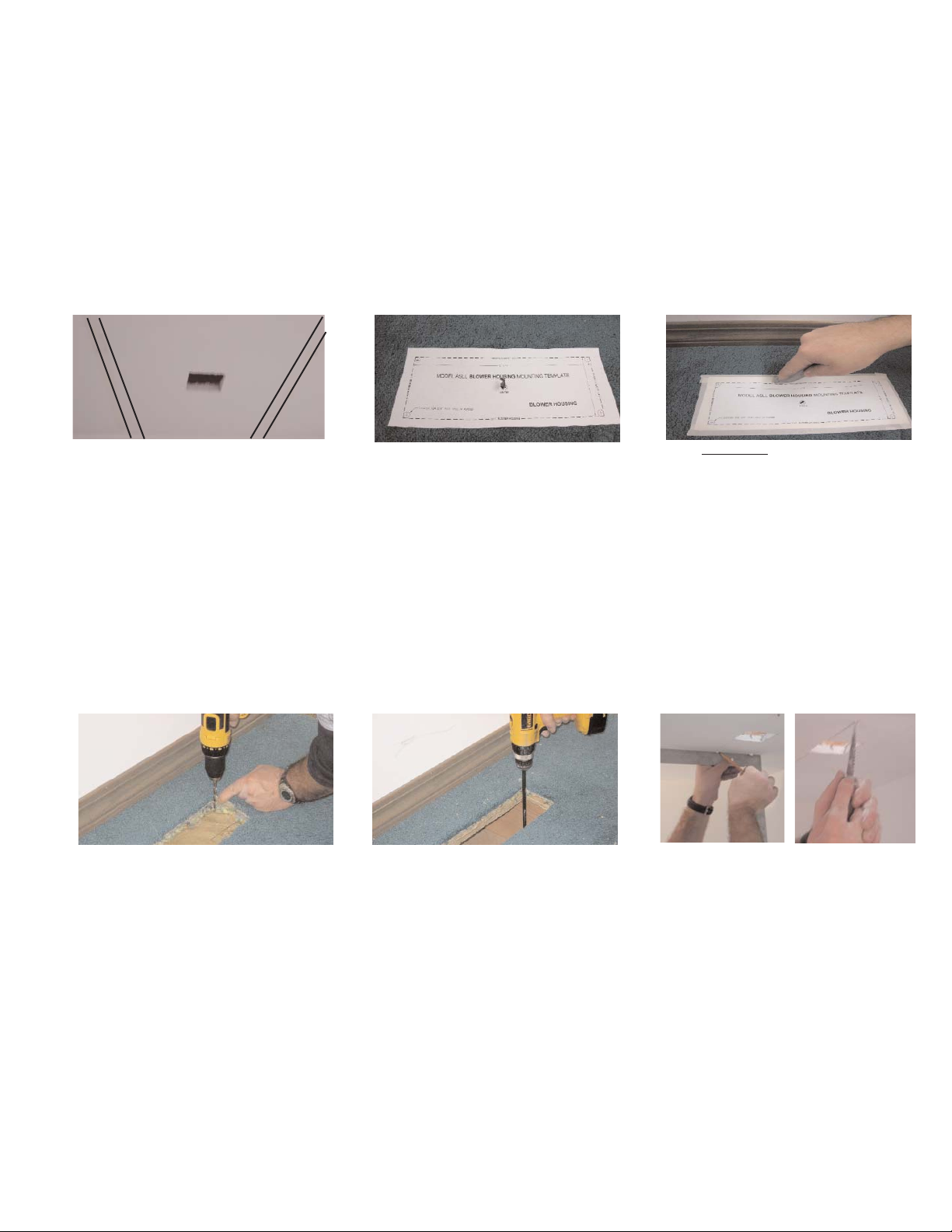
1. Proceed to step 2 if ceiling is unfinished. If ceiling is finished use a stud finder to locate the inside edges of the joist/truss ASLL will
be installed between. Apply masking tape on ceiling along joist/trusses in the desired location ASLL will be installed in. Make sure a
proper analysis as noted above has taken place before cutting hole in ceiling. In the center of the tape cut a 3” x 3” inspection hole
to review the intended installation area using a flashlight and small mirror if necessary, (See Diagram B).
NOTE: The following installation illustrations show the upper level floor with carpeting.
2. If floor above has carpeting it may be desirable to pull carpeting back if possible. If it is a good installation area, slowly drill a small
pilot hole with a 1/4” drill bit through the 3” x 3” inspection hole or center of joist/truss area up through subfloor. Drill bit might cause
carpet to unravel so be cautious. Once you go through subfloor reverse out of the hole. Use an extended screw driver or scratch awl
to push through the carpet above.
DIAGRAM A
UPFLOW
INSTALLATION
DOWNFLOW
INSTALLATION
THE FOLLOWING STEPS ARE FOR AN UPFLOW INSTALLATION
Page 3
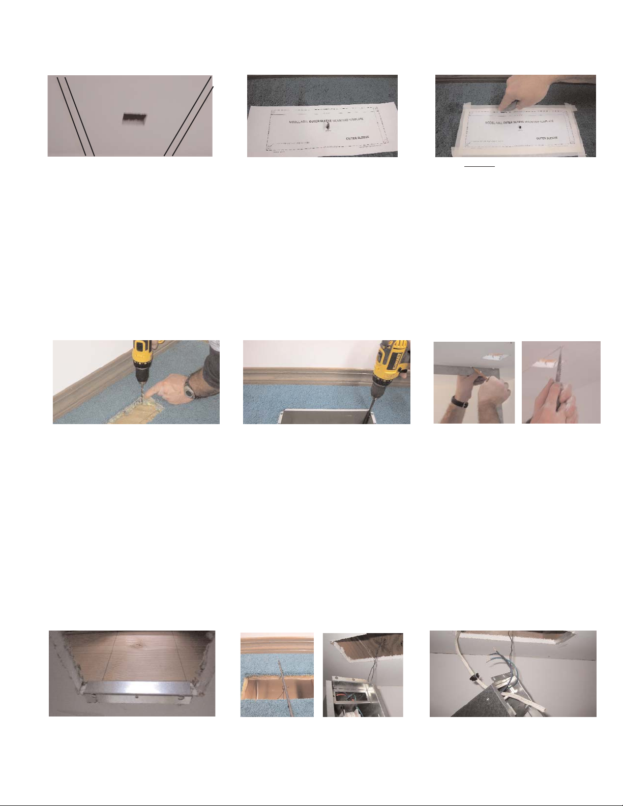
3. Place ASLL Outer Sleeve template center alignment hole over drill bit or screw driver. Align template cutout lines parallel with
baseboard and tape template to floor, (See Diagram C). Use a utility knife and cut out carpeting and pad along Outer Sleeve
template lines denoted, (See Diagram D).
4. Drill the 4 corners out on floor with a 3/8” drill bit and saw opening out using a jig saw or reciprocating saw. The final rough-in opening in
the floor for an Upflow application must measure 4 5/16” x 12 5/16” for Outer Sleeve. IMPORTANT: Rough-in openings must
not exceed dimensions provided or Outer Sleeve flange may fall through opening, (See Diagram E).
5. Proceed to step 8 if ceiling below is unfinished. Slide the Outer Sleeve through the floor. Using a 1/4” long drill bit, follow the corners of
the Outer Sleeve straight down and drill 4 holes through the ceiling material below, (See Diagram F). Connect the 4 holes on the ceiling
below with a straight edge and compare the dimensions on the ceiling to Blower Housing template dimensions which measure 4 1/16” x
12 5/16”, See Diagram G).
6. If ceiling is sheetrock use a sheetrock saw and follow the lines from step 5 and cut out ceiling opening, (See Diagram G). If ceiling is
not sheetrock, use a jig saw or reciprocating saw. IMPORTANT: Both openings should be directly centered above one another.
7. If ceiling is sheetrock or ceiling tile, slide sheetrock mounting brackets over sheet rock ends. The 2 large holes in brackets must face
down, (See Diagram H). IMPORTANT: If using ceiling tile, it must be able to support 8 pounds to support the ASLL blower. If ceiling
tile is not adequate enough to support the ASLL then the ASLL must be framed in and properly supported by ceiling track.
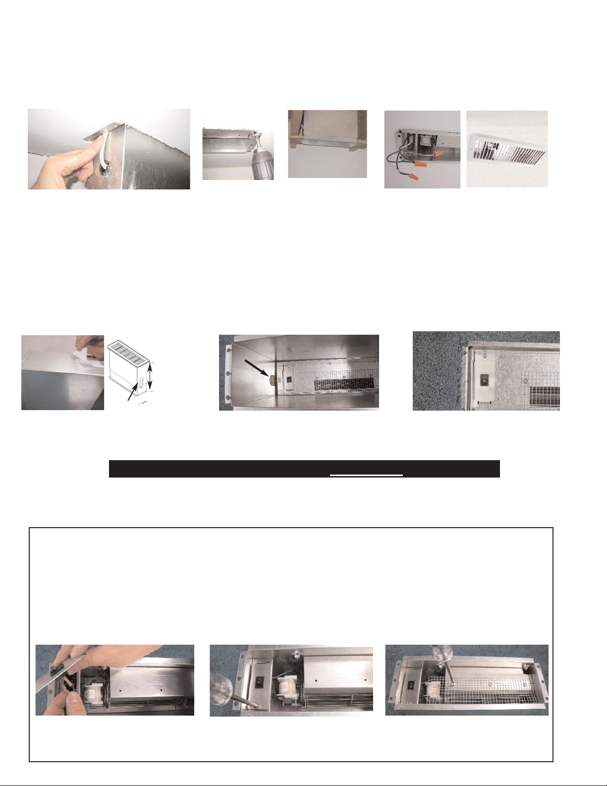
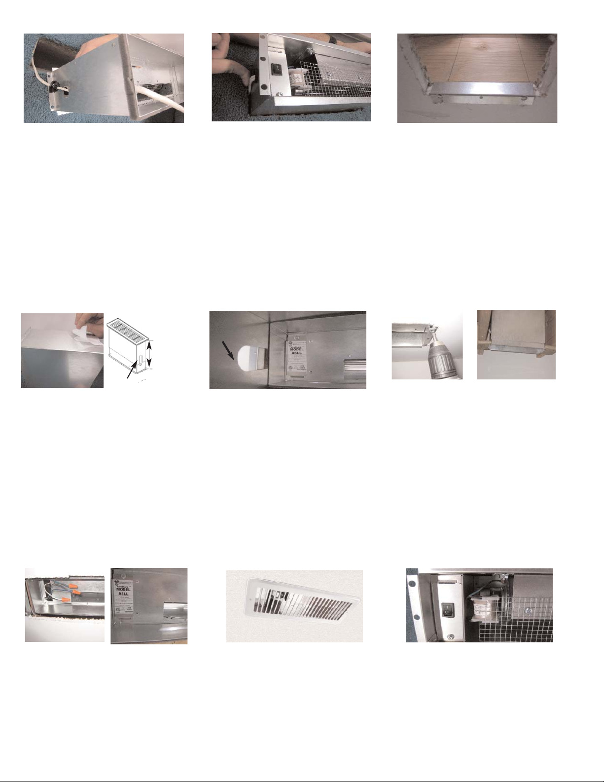
8. Use a rod with wire attached to ASLL Blower Housing mounting bracket to suspend ASLL blower from floor above while
wiring, (See Diagram I).
9. Supply electrical power through ceiling opening on the side of ASLL where power will enter unit. See “Wiring” section for wiring
specifics. Use provided strain relief bushing for standard 14-2 w/ground NM-B nonmetallic sheathed cable (Romex) and snap into
place in 7/8” knockout on ASLL electrical box with about 6-8” of wire pushed into ASLL electrical box, (See Diagram J). Push wire up
tight against ASLL Blower Housing and slide the ASLL up through the hole in the ceiling until the flange of the ASLL blower section
meets the ceiling, (See Diagram K).
DIAGRAM B DIAGRAM C DIAGRAM D
IF CEILING IS FINISHED, PLACE TAPE ALONG
JOIST/TRUSS. CUT A 3” INSPECTION HOLE TO
VERIFY IT IS A GOOD INSTALLATION LOCATION.
PLACE ASLL OUTER SLEEVE TEMPLATE CENTER ALIGNMENT HOLE OVER DRILL BIT OR
SCREW DRIVER.
FOR AN UPFLOW APPLICATION CUT OUT CARPET & ROUGH-IN OPENING USING OUTER
SLEEVE TEMPLATE (4 5/16” X 12 5/16”).
DIAGRAM E
DRILL OUT CORNERS WITH 3/8” DRILL BIT.
IMPORTANT: ROUGH-IN OPENING FOR OUTER
SLEEVE MUST NOT EXCEED 4 5/16” X 12 5/16”.
DIAGRAM F DIAGRAM G
CONNECT (4) HOLES WITH A STRAIGHT EDGE
AND MAKE SURE BLOWER HOUSING DIMENSIONS MEASURE 4 1/16” X 12 5/16”. CUT OUT
OPENING WITH SHEETROCK OR JIG SAW.
DIAGRAM I
SUPPORT ASLL BLOWER FROM ABOVE BY
USING ASLL MOUNTING FLANGE AND MECHANICS WIRE OR OTHER SUITABLE METHOD.
SNAP PROVIDED STRAIN RELIEF BUSHING INTO
ASLL ELECTRICAL BOX WITH 6-8” OF WIRE IN
ELECTRICAL BOX.
DIAGRAM J
IF CEILING BELOW IS FINISHED, DRILL (4) 1/4”
HOLES THROUGH CEILING USING EACH OF
THE 4 CORNERS OF OUTER SLEEVE AS A
GUIDE.
DIAGRAM H
INSTALL SHEETROCK BRACKETS ON BOTH
ENDS OF OPENING WITH LARGER HOLES IN
BRACKETS FACING DOWN.
Page 4
10.Using the (4) provided black screws, align holes on ASLL Blower Housing mounting bracket with holes in sheetrock mounting bracket (utilized if ceiling is sheetrock or ceiling tile). Install the (4) screws straight up. The screws must grip the sheetrock mounting
bracket small grip hole. Do not over tighten screws, (See Diagram L). If ceiling is unfinished cut (2) pieces from floor cutout
material and secure each piece to the joist/truss and install (4) screws in ASLL Blower Housing mounting bracket, (See Diagram L).
11. Wire the ASLL as illustrated in the “Wiring” section. Push the wires into the ASLL electrical box and install electrical box cover
and ceiling grille with the provided screws, (See Diagram M). Ceiling grille may be painted if desired.
12.IMPORTANT: If the combined width of the Joist/Truss thickness, ceiling and subfloor is over 13”, adhere both air flow leakage stickers
over electrical relief slot opening in Outer Sleeve to prevent air leakage into joist/truss cavity, (See Diagram N).
13.Install the Outer Sleeve in floor. CAUTION: When installing Outer Sleeve make sure electrical relief opening is on the side electrical
enters ASLL, (See Diagram O).
14.Unit can be operated by switching the on/off switch below floor grille, (See Diagram P). ASLL can also be wired into a 120 VAC wall
switch or thermostat if desired, see “Wiring” for details. Insert the floor grille.
IMPORTANT: An in depth investigation of the floor joist/truss layout is required prior to installation. Avoid a joist/truss cavity that is a
path for plumbing supply lines, drains, vents or ductwork. Also confirm foundation block and upstairs walls do not obstruct installation. If
wiring to an existing outlet, it is best to select a joist/truss section that contains an electrical outlet for wiring.
DIAGRAM P
ASLL CAN BE OPERATED BY ON/OFF
SWITCH THROUGH FLOOR GRILLE OR IT
CAN BE WIRED INTO A 120 VAC WALL
SWITCH OR THERMOSTAT.
IMPORTANT: IF ASLL OUTER SLEEVE WILL BE
EXPANDED OVER 13”, AIR FLOW LEAKAGE
STICKERS MUST BE APPLIED OVER ELECTRICAL RELIEF SLOT TO PREVENT AIR LEAKAGE.
DIAGRAM N
The following steps must be completed to convert the ASLL from an upflow to a downflow installation.
Remove (1) screw from On/Off switch coverplate. Pull On/Off cover assembly out and remove Blue & Red wires connected to
switch. Turn ASLL over and remove electrical access coverplate from opposite side. Pull Blue & Red wires through and
connect to On/Off switch terminals - Red to center, Blue to other, (See Diagram A1). Reinstall On/Off assembly with (1) screw,
(See Diagram A2). Reinstall electrical access coverplate on opposite side.
Remove (3) screws from blower guard screen, turn ASLL over and and reinstall blower guard screen flush against both outer
edges of ASLL blower housing to prevent contact with moving blower wheel, (See Diagram A3).
FEED ON/OFF SWITCH WIRES THROUGH FROM
OTHER SIDE AND PUSH ON MALE SWITCH TERMINALS - RED TO CENTER, BLUE TO OTHER.
INSTALL ON/OFF ASSEMBLY WITH (1) SCREW
REMOVED FROM OTHER SIDE. REINSTALL
ELECTRICAL ACCESS COVERPLATE ON OPPOSITE SIDE.
DIAGRAM A1 DIAGRAM A2
INSTALL BLOWER GUARD SCREEN WITH (3)
SCREWS REMOVED FROM OTHER SIDE.
DIAGRAM A3
DIAGRAM O
INSTALL OUTER SLEEVE THROUGH FLOOR.
CAUTION: ELECTRICAL RELIEF SLOT MUST BE
ON SIDE ELECTRICAL ENTERS ASLL OR DAMAGE MAY RESULT.
OUTER SLEEVE
ELECTRICAL RELIEF SLOT
THE FOLLOWING STEPS ARE FOR A DOWNFLOW INSTALLATION
APPLY
STICKERS
OVER
RELIEF
SLOT IF
EXPAND
OVER 13”
RELIEF
SLOT
DIAGRAM L
INSTALL (4) SCREWS
IN BLOWER HOUSING
MOUNTING FLANGE
INTO SHEETROCK
MOUNTING BRACKET.
FOR UNFINISHED CEILINGS, SCREW PIECES
OF WOOD CUT FROM
FLOOR OPENING TO
JOIST/TRUSS TO SUPPORT ASLL BLOWER.
INSTALL CEILING GRILLE
INTO SHEETROCK
MOUNTING BRACKET
WITH PROVIDED SCREWS.
DIAGRAM M
WIRE PER WIRING
DIAGRAM. INSTALL
ASLL ELECTRICAL
BOX COVER.
DIAGRAM K
PUSH WIRE UP TIGHT AGAINST ASLL BLOWER
HOUSING AND SLIDE UP UNTIL FLUSH WITH
CEILING.
Page 5
1. Proceed to step 2 if ceiling is unfinished. If ceiling is finished use a stud finder to locate the inside edges of the joist/truss cavity the
ASLL will be installed between. Apply masking tape on ceiling along joist/trusses in the desired location ASLL will be installed in.
Make sure a proper analysis as noted above has taken place before cutting hole in ceiling. In the center of the tape cut a 3” x 3”
inspection hole to review the intended installation area using a flashlight and small mirror if necessary, (See Diagram B1).
NOTE: The following installation illustrations show the upper level floor with carpeting.
2. If floor above has carpeting it may be desirable to pull carpeting back if possible. If it is a good installation area, slowly drill a small
pilot hole with a 1/4” drill bit through the 3” x 3” inspection hole or center of joist/truss up through subfloor. Drill bit might cause carpet to unravel so be cautious. Once you go through subfloor reverse out of the hole. Use an extended screw driver or scratch awl
to push through the carpet above.
3. Place ASLL Blower Housing template center alignment hole over drill bit or screw driver. Align template cutout lines parallel with
baseboard and tape template to floor, (See Diagram C1). Use a utility knife and cut out carpeting and pad along Blower Housing
template lines denoted, (See Diagram D1).
4. Drill the 4 corners out on floor with a 3/8” drill bit and saw opening out using a jig saw or reciprocating saw. The final rough-in opening in
the floor for a Downflow application must measure 4 1/16” x 12 5/16” for Blower Housing. IMPORTANT: Rough-in openings must
not exceed dimensions provided or Blower Housing flange may fall through opening, (See Diagram E1).
5. Proceed to step 7 if ceiling below is unfinished. Using a 1/4” long drill bit, follow the corners of the Blower Housing cutout straight down
and drill 4 holes through the ceiling material below, (See Diagram F1). Connect the 4 holes on the ceiling below with a straight edge and
compare the dimensions on the ceiling to Outer Sleeve template dimensions which measure 4 5/16” x 12 5/16”, (See Diagram G1).
6. If ceiling is sheetrock use a sheetrock saw and follow the lines from step 5 and cut out ceiling opening, (See Diagram G1). If ceiling
is not sheetrock, use a jig saw or reciprocating saw. IMPORTANT: Both openings should be directly centered above one another.
7. Supply electrical power to side of ASLL where power will enter unit. See “Wiring” section for wiring specifics. Use provided strain
relief bushing for standard 14-2 w/ground NM-B nonmetallic sheathed cable (Romex) and snap into place in 7/8” knockout on
ASLL electrical box with about 6-8” of wire pushed into ASLL electrical box, (See Diagram H1).
8. Push wire up tight against ASLL Blower Housing and insert the ASLL blower through floor opening until flange meets floor, (See
Diagram I1).
9. If ceiling is sheetrock or ceiling tile, slide sheetrock mounting brackets over sheet rock ends. The 2 large holes in brackets must
face down, (See Diagram J1).
DIAGRAM B1 DIAGRAM C1 DIAGRAM D1
IF CEILING IS FINISHED, PLACE TAPE ALONG
JOIST/TRUSS. CUT A 3” INSPECTION HOLE TO
VERIFY IT IS A GOOD INSTALLATION LOCATION.
FOR A DOWNFLOW
APPLICATION CUT OUT
CARPET & ROUGH-IN OPENING USING BLOWER HOUSING TEMPLATE (4 1/16” X 12 5/16”).
DIAGRAM E1
DRILL OUT CORNERS WITH 3/8” DRILL BIT.
IMPORTANT: ROUGH-IN OPENING FOR BLOWER
HOUSING MUST NOT EXCEED 4 1/16” X 12 5/16”.
DIAGRAM F1
IF CEILING BELOW IS FINISHED, DRILL (4) 1/4”
HOLES STRAIGHT DOWN THROUGH CEILING
USING EACH OF THE 4 CORNERS OF BLOWER
HOUSING CUT OUT AS A GUIDE.
PLACE ASLL BLOWER HOUSING TEMPLATE
CENTER ALIGNMENT HOLE OVER DRILL BIT OR
SCREW DRIVER.
DIAGRAM G1
CONNECT (4) HOLES WITH A STRAIGHT EDGE
AND MAKE SURE OUTER SLEEVE DIMENSIONS
MEASURE 4 5/16” X 12 5/16”. CUT OUT OPENING
WITH SHEETROCK OR JIG SAW.
Page 6
10.IMPORTANT: If the combined width of the Joist/Truss thickness, ceiling and subfloor require ASLL Blower sleeve to be expanded
over 13”, adhere both air flow leakage stickers over electrical relief slot opening in Outer Sleeve to prevent air leakage into joist/truss cavity,
(See Diagram K1).
11.Install the Outer Sleeve over Blower Housing. CAUTION: When installing Outer Sleeve make sure electrical relief opening is on the
side electrical enters ASLL, (See Diagram L1).
12.Using the (4) provided black screws, align holes on ASLL Outer Sleeve mounting bracket with holes in sheetrock mounting bracket (utilized if ceiling is sheetrock or ceiling tile). Install the (4) screws straight up. The screws must grip the sheetrock mounting
bracket small grip hole if utilized. Do not over tighten screws, (See Diagram M1). If ceiling is unfinished cut (2) pieces from floor
cutout material and secure each piece to the joist/truss and install (4) screws in ASLL Outer Sleeve mounting bracket, (See
Diagram M1).
13.Wire the ASLL as illustrated in the “Wiring” section. Push the wires into the ASLL electrical box and install electrical box cover,
(See Diagram N1).
14.Install ceiling grille into sheetrock mounting bracket with the provided screws, (See Diagram O1). Ceiling grille may be painted if
desired.
15.Insert the floor grille. Unit can be operated by switching the on/off switch below floor grille, (See Diagram P1). ASLL can also be
wired into a 120 VAC wall switch or thermostat if desired, see “Wiring” for details.
DIAGRAM N1
WIRE PER WIRING
DIAGRAM. INSTALL
ELECTRICAL COVER.
INSTALL ASLL ELECTRICAL BOX COVER.
DIAGRAM M1
INSTALL (4) SCREWS
IN OUTER SLEEVE
MOUNTING FLANGE
INTO SHEETROCK
MOUNTING BRACKET.
FOR UNFINISHED CEILINGS, SCREW PIECES
OF WOOD CUT FROM
FLOOR OPENING TO
JOIST/TRUSS TO SUPPORT ASLL BLOWER.
DIAGRAM L1
INSTALL OUTER SLEEVE THROUGH CEILING.
CAUTION: ELECTRICAL RELIEF SLOT MUST BE
ON SIDE ELECTRICAL ENTERS ASLL OR DAMAGE WILL RESULT.
DIAGRAM P1
ASLL CAN BE OPERATED BY ON/OFF
SWITCH THROUGH FLOOR GRILLE OR IT
CAN BE WIRED INTO A 120 VAC WALL
SWITCH OR THERMOSTAT.
DIAGRAM O1
INSTALL CEILING GRILLE INTO
SHEETROCK MOUNTING BRACKET WITH
PROVIDED SCREWS. GRILLE MAY BE
PAINTED IF DESIRED.
OUTER SLEEVE
ELECTRICAL RELIEF SLOT
IMPORTANT: IF ASLL OUTER SLEEVE WILL BE
EXPANDED OVER 13”, AIR FLOW LEAKAGE
STICKERS MUST BE APPLIED OVER ELECTRICAL RELIEF SLOT TO PREVENT AIR LEAKAGE.
DIAGRAM K1
APPLY
STICKERS
OVER
RELIEF
SLOT IF
EXPAND
OVER 13”
RELIEF
SLOT
DIAGRAM I1
PUSH WIRE UP TIGHT AGAINST ASLL BLOWER
HOUSING AND INSERT THE ASLL THROUGH
FLOOR OPENING.
DIAGRAM J1
INSTALL SHEETROCK BRACKETS ON BOTH
ENDS OF OPENING WITH LARGER HOLES IN
BRACKETS FACING DOWN.
DIAGRAM H1
SNAP PROVIDED STRAIN RELIEF BUSHING
INTO ASLL ELECTRICAL BOX WITH 6-8” OF
WIRE IN ELECTRICAL BOX.
Page 7
WIRING
WIRING
Disrupt power at circuit breaker to outlets within the joist/truss cavity you will be working.
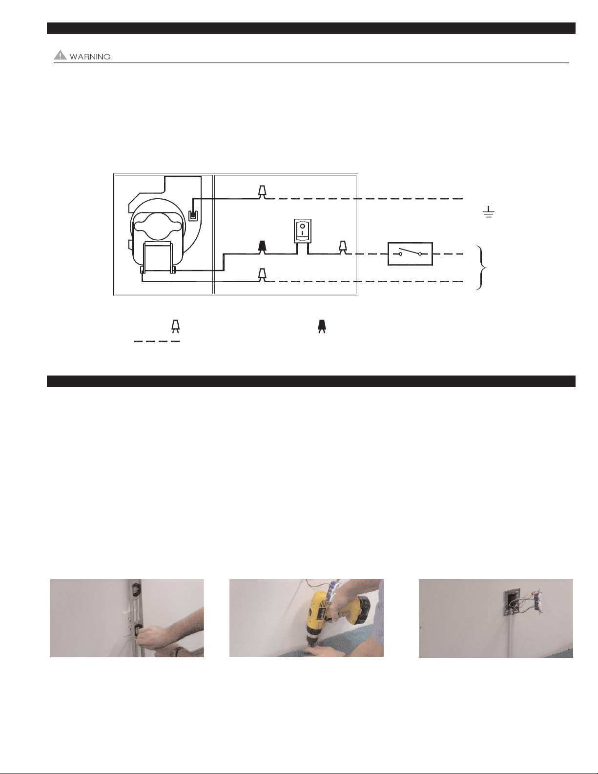
1. Wire Blower into 120 VAC power source as shown in wiring connection diagram. NOTE: Optional 120 VAC wall switch or thermostat
may be desired.
2. Attach ASLL electrical box coverplate, (See Diagram N1).
OPTIONAL SURFACE WIRING INSTALLATION
Surface wiring materials can be found at most do-it-yourself hardware and home improvement stores. If wiring to an existing outlet using
surface wiring, it is best to select a joist/truss section that contains an electrical outlet to wire into. If that is not possible, run surface
wiring track horizontal along wall and use a 90 degree track piece to route down to floor in desired location ASLL will be installed, (See
Diagram U).
WARNING: To reduce the risk of fire or electrical shock remove power from outlet at circuit braker before wiring. Use a volt meter to
assure that power is not supplied to outlet before continuing.
1. Mark a vertical level line down center of outlet. Remove or cut out baseboard for surface wiring track, (See Diagram Q).
2. Pull back carpet and Drill 1/2” hole parallel to wall through floor along edge of wall where line meets floor for standard 14-2 w/ground
NM-B nonmetallic sheathed cable (Romex), (See Diagram R).
3. Install surface box plate on existing outlet. Feed wiring down from electrical box through track to ASLL Blower. Connect Black wire
to outlet “Hot” and White wire to outlet neutral. Connect ground wire to outlet ground wires, (See Diagram S).
DIAGRAM Q DIAGRAM R DIAGRAM S
MARK A VERTICAL LEVEL LINE DOWN FROM
OUTLET.
INSTALL SURFACE WIRING BOX PLATE ON
EXISTING OUTLET AND WIRE POWER FEED IN
FOR ASLL.
DRILL 1/2” HOLE PARALLEL TO WALL THROUGH
FLOOR WHERE VERTICAL LINE FROM OUTLET
MEETS FLOOR.
L1
50/60 Hz
120 VAC
N
S1
GROUND
ELECTRICAL BOX
8050019 3/19/09
MOTOR
GREEN
WHITE
BLACK
= WIRE NUTS SUPPLIED BY OTHERS
BLOWER
= WIRING SUPPLIED BY OTHERS
= OPTIONAL 120 VAC T-STAT, WALL SWITCH, ETC.
S1
RED BLUE
= FACTORY WIRE NUT CONNECTION
AIRESHARETMMODEL ASLL WIRING CONNECTIONS
Page 8

4. Install surface wiring electrical box and coverplate. WARNING: Do not turn circuit braker back on until ASLL Blower is
completely wired and installed. Reestabish power to outlet by turning on circuit braker. See Diagram T for ASLL Surface wiring
final installation photo.
AINTENANCE
MAINTENANCE
The AireShare™ ASLL Blower wheel should inspected annually and carefully cleaned or vacuumed with a bristle brush head if necessary. The motor is permanently lubricated and requires no maintenance.
REPLACEMENT PARTS AND WARRANTY
Component Part Number Component Part Number
ASLL Floor Grille 950-3350 ASLL Blower Assembly 950-3305
ASLL Ceiling Grille 950-3351 ASLL On/Off Switch 950-3304
TJERNLUND LIMITED ONE YEAR WARRANTY
Tjernlund Products, Inc. warrants to the original purchaser of this product that the product will be free from defects due to faulty material or workmanship for a period of (1)
year from the date of original purchase or delivery to the original purchaser, whichever is earlier. Remedies under this warranty are limited to repairing or replacing, at our
option, any product which shall, within the above stated warranty period, be returned to Tjernlund Products, Inc. at the address listed below, postage prepaid. THERE ARE
NO WARRANTIES WHICH EXTEND BEYOND THE DESCRIPTION ON THE FACE HEREOF, AND TJERNLUND PRODUCTS, INC. EXPRESSLY DISCLAIMS LIABILITY
FOR INCIDENTAL OR CONSEQUENTIAL DAMAGES ARISING FROM THE USE OF THIS PRODUCT. THIS WARRANTY IS IN LIEU OF ALL OTHER EXPRESS WARRANTIES AND NO AGENT IS AUTHORIZED TO ASSUME FOR US ANY LIABILITY ADDITIONAL TO THOSE SET FORTH IN THIS LIMITED WARRANTY. IMPLIED
WARRANTIES ARE LIMITED TO THE STATED DURATION OF THIS LIMITED WARRANTY. Some states do not allow limitation on how long an implied warranty lasts,
so that limitation may not apply to you. In addition, some states do not allow the exclusion or limitation of incidental or consequential damages, so that above limitation or
exclusion may not apply to you. This warranty gives you specific legal rights and you may also have other rights which may vary from State to State. Send all inquiries
regarding warranty work to Tjernlund Products, Inc. 1601 9th Street, White Bear Lake, MN 55110-6794. Phone (651) 426-2993 • (800) 255-4208 • Fax (651) 426-9547 •
Email fanmail@tjfans.com.
DIAGRAM T DIAGRAM U
FINAL SURFACE WIRING INSTALLATION WITH
ASLL.
SURFACE WIRING CAN ALSO BE RAN HORIZONTAL IF THERE IS NO ELECTRICAL OUTLET IN
THE JOIST/TRUSS CAVITY ASLL WILL BE
INSTALLED IN.
 Loading...