

Page 1
TJERNLUND PRODUCTS, INC.
1601 Ninth Street • White Bear Lake, MN 55110-6794
PHONE (800) 255-4208 • (651) 426-2993 • FAX (651) 426-9547
Visit our web site • www.tjernlund.com
READ OWNERS INSTRUCTIONS CARE-
FULLY PRIOR TO INSTALLATION.
THESE INSTRUCTIONS MUST REMAIN
WITH EQUIPMENT. DO NOT DESTROY.
AIRESHARETMROOM-TO-ROOM TRANSFER FAN
MODEL AS2
©2014 TJERNLUND PRODUCTS, INC. ALL RIGHTS RESERVED P/N: 8504213
DESCRIPTION
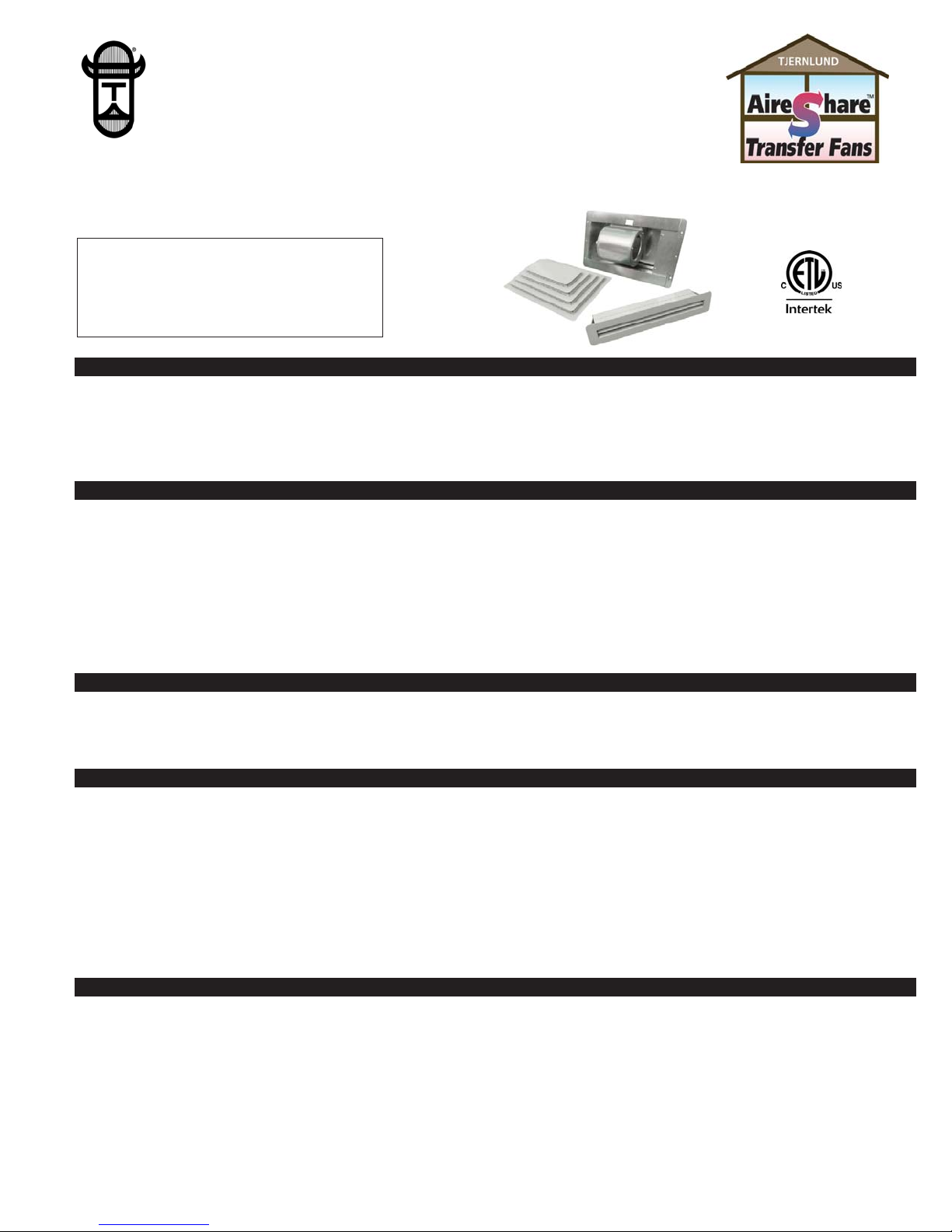
The Tjernlund AireShare™ Room-to-Room Transfer fans distribute air from one conditioned space to another. Virtually every home has
a room that is uncomfortably hot or cold from which some of that room’s air can be shared with an adjacent room, making the temperature of both rooms more comfortable. The AireShare™ transfers air through the wall cavity created between two wall studs. The
AireShare’s unique option of moving the air up or down within the wall cavity allows for optimum heat transfer between rooms. In addition, locating the Grille and Diffuser, one high the other low, prevents the transfer of light and sound between these adjacent rooms.
AS2 SPECIFICATIONS & COMPONENTS
GENERAL INFORMATION
Every Tjernlund AireShare™ Room-to-Room Transfer fan is electrically factory line tested before shipment.
After opening carton, inspect thoroughly for shipping damage. Impeller should rotate freely and all electrical wires and connections
should be secured. If any damage is found, notify freight carrier and your distributor immediately and file a concealed damage claim.
SPEED SELECTION ADVICE
Since it is impractical to calculate heating and cooling loads for the variety of geographic areas, construction methods and the temperature of transferred air we base our model selection advice on providing a minimum of 3 Air Changes/Hour (ACH) to the target room.
Door under-cuts or pressure relief transfer grilles in the target room are necessary for proper AireShare performance.
(AireShare CFM x 60) / (L x W x H of target room) = ACH NOTE: Aireshare CFM is 110 on High, 95 on Med and 80 on Low
3-4 Air Changes/hour (ACH) recommended for best temperature equalization.
4-5 Air Changes/hour (ACH) recommended for rooms with high cooling or heating loads. Examples include rooms with extensive outside walls, windows, over tuck under garages or in extreme climates. More than one AireShare transfer fan can be installed to reach
desired number of air changes for large spaces.
INSTALLATION RESTRICTIONS
The AireShare™ Transfer fan must be installed by a qualified installer in accordance with these instructions and all local codes, including fire-rated construction. In their absence, install in accordance with the latest editions of the International Residential Code and
International Electrical Code. Improper installation can create a hazardous condition such as fire, electric shock or personal injury. To
reduce these risks significantly, use this device only in the manner intended by the manufacturer. If you have questions about proper
usage of this device, call Tjernlund.
Always disconnect the AireShare™ Transfer fan from its power source before installation and servicing.
IMPORTANT: An in depth investigation of the wall layout is required prior to installation. Avoid a stud wall section that is a path for
plumbing supply lines, drains and vents. Avoid a stud wall section that is insulated or being used as a return air duct for a forced air
system. If stud walls are constructed with metal studs, order Tjernlund Model DK2 Duct Kit or seal all metal stud openings.
Blower: 3 Speed: 110 CFM, 95 CFM, 80 CFM (Wire for desired speed upon install or use optional AS2SW3 3-speed switch kit.)
Motor: 120 Volts ~ 60 Hz ~ Thermal Switch Protected (Moter Protection Thermique)
0.50 amps maximum, Watts (30 High, 21 Med,16 Low)
Impeller: Dual Inlet, Low RPM
Dimensions: Diffuser: 3” x 15 1/8” (flush) Diffuser Rough Opening: 1 1/4” High x 13 5/8” Wide
Blower Grille: 16” x 10” x 2 1/2” Blower Rough Opening: 7 1/4” High x 14 1/2” Wide
Color: Neutral White
Page 2
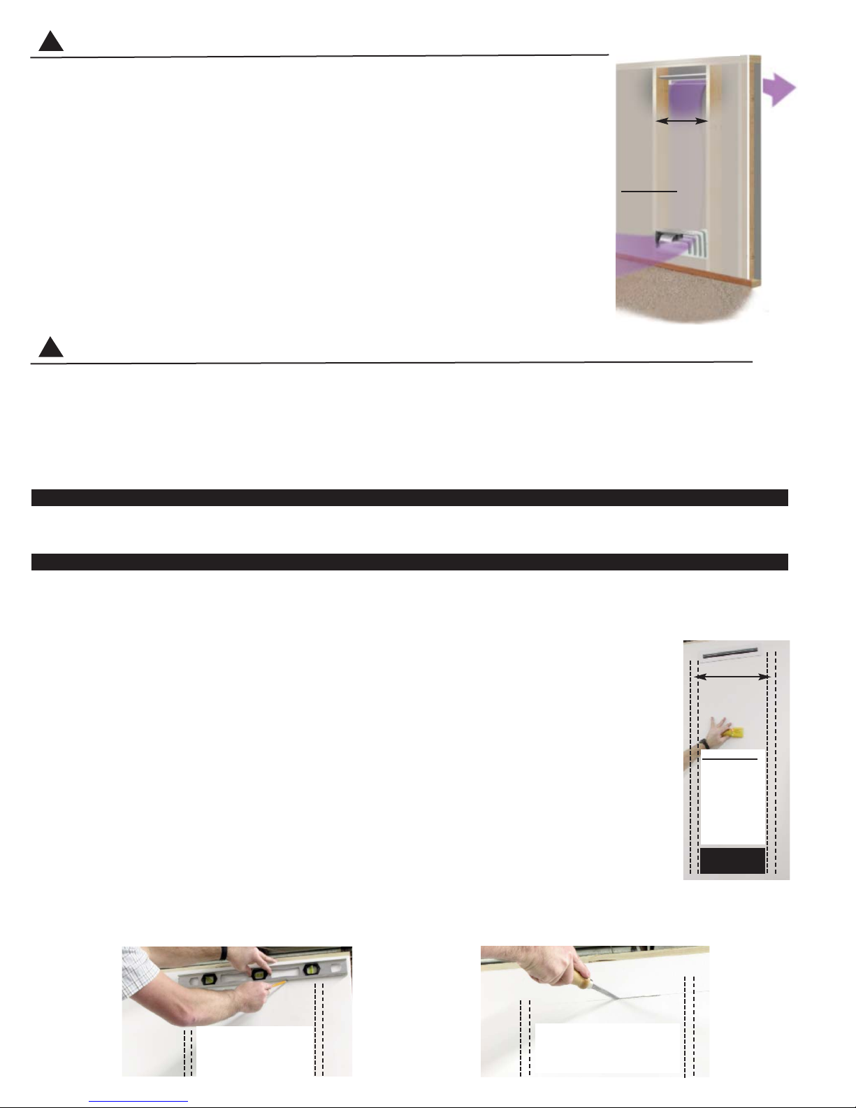
DIAGRAM C DIAGRAM D
LEVEL AND MARK A
LINE BETWEEN STUDS
WHERE DIFFUSER IS
TO BE INSTALLED.
CAREFULLY MAKE A LEVEL
HORIZONTAL CUT IN SHEETROCK BETWEEN STUDS NO
LONGER THAN 13 5/8”.
• The AireShare™ is for general ventilating use only. Do not use to exhaust hazardous or explosive
materials or vapors.
• The AireShare™ may not be installed in a ceiling.
• The AireShare™ may not be installed in an outside wall.
• The AireShare™ may not be installed in a wall rated as a “fire wall.”
• The AireShare™ may not be used to move air from one floor (story) to another floor.
• The AireShare™ may not be used to move moisture-laden air from sources such as bathrooms
and kitchens. (Ne pas installer pres d'un apparel.)
• The AireShare™ may not be used in a window. (Ne pas utilliser dans une penetre.)
WARNING: To reduce the risk of fire, electrical shock and injury to persons, the AireShare™ must
be installed with the Diffuser that was provided. Do not use this product with any Diffuser other than
the AS2 Diffuser.
WARNING: To reduce the risk of fire or electrical shock, do not use this fan with any solid state speed
control devices. (Avertissment: Ne Convient pas a Des Regulaters De Vitesse a Semi-Conducteurs.)
Disrupt power at circuit breaker to outlets and switches within the stud wall you will be working.
BEFORE YOU START:
Determine the stud wall section that you want to use to mount the Blower and Diffuser. It may be preferable to select a stud wall section
that contains an electrical outlet for wiring. IMPORTANT: Wall studs must be spaced a minimum of 16” o.c., (See Diagram A). Mark
inside edges of studs the Aireshare
TM
will be installed between and verify there is at least 14” between the inside edges. Slide a stud
finder down the wall between the studs to help verify the stud wall cavity is completely open, (See Diagram B).
TOOLS REQUIRED
Hand Sheetrock Saw Phillips & Straight Screwdrivers Level Tape Measure Utility Knife or Scissors Wire Stripper
INSTALLING DISCHARGE DIFFUSER
WARNING: Disrupt power at circuit breaker to outlets and switches within the stud wall you will be working. When sawing through
sheetrock you must stop if you detect the saw blade coming in contact with any wiring or plumbing. Investigate further to determine
if it is possible to safely continue to use this wall cavity space. Switch to another stud wall cavity if necessary.
NOTE: Typical installations will have the Diffuser high and the Blower low, but there may be instances where it
is desirable to have the Blower mounted high and the Diffuser low to take air from the ceiling level.
IMPORTANT: Install Diffuser first if mounting the Blower down low and the Diffuser high so sheetrock from the
Diffuser cut out does not fall into wall cavity and damage Blower. Install the Blower first if mounting the Blower high
and Diffuser low so sheetrock from the Blower cut out does not fall into wall cavity and damage Diffuser.
1. Determine if you would like a high or low discharge. The Diffuser may be mounted as close as 3" above the top
of Blower cut out opening or as close as 3" to the ceiling.
2. Level and mark a line between studs where you want the top of the Diffuser, (See Diagram C)
3. Using a hand sheetrock saw carefully make a horizontal cut along the line. Cut the sheetrock completely until you
come in contact with the opposite stud. NOTE: If studs are spaced greater than 16” o.c., the horizontal cut line
should not exceed 13 5/8”, (See Diagram D).
DIAGRAM A
Wall studs must be
spaced a minimum
of 16” o.c.
IMPORTANT: Wall cavity
between studs must be completely open between Blower
Intake and Diffuser
DIAGRAM B
Wall studs must
be spaced a
minimum
of 16” o.c.
BLOWER
OPENING
DIFFUSER
IMPORTANT:
Wall cavity
between studs
must be completely open
between
Blower intake
and Diffuser
WARNING
!
WARNING
!
Page 3

4. Cut out Diffuser template on dashed lines. Align the top of template with the wall cut and center it so that there is an equal space
between the right and left edges of the template and ends of the cut in the sheetrock. Mark all 4 corners of template, connect with
a straight edge and cut Diffuser opening in wall (Diffuser opening should be 1 1/4” high x 13 5/8” wide), (See Diagram E).
5. Insert Diffuser with the air scoop on the back pointing towards the Blower. Adjust tangs on the sides if necessary to secure a tight fit
into the wall opening, (See Diagram F).
BLOWER INSTALLATION
WARNING: Disrupt power at circuit breaker to outlets and switches within the stud wall you will be working. When sawing through
sheetrock you must stop if you detect the saw blade coming in contact with any wiring or plumbing. Investigate further to determine if it
is possible to safely continue to use this wall cavity space. Switch to another stud wall cavity if necessary.
NOTE: Typical installations will have the Diffuser high and the Blower low, but there may be instances where it is desirable to have
the Blower mounted high and the Diffuser low to take air from the ceiling level.
IMPORTANT: Install Diffuser first if mounting the Blower down low and the Diffuser high so sheetrock from the Diffuser cut out does not
fall into wall cavity and damage Blower. Install the Blower first if mounting the Blower high and Diffuser low so sheetrock from the
Blower cut out does not fall into wall cavity and damage Diffuser.
1. Using a stud finder mark the center of the stud on each side of the wall cavity that the AS2 Blower and Intake Grille will be installed,
(See Diagram G). These instructions assume standard 16” on center studs.
2. Position the AS2 Intake Grille at the desired height on the wall, centered between the two 16” on center studs. Level and lightly mark
the grille position through the two mounting holes. IMPORTANT: Make sure Intake Grille flanges do not interfere with baseboards &
outlets. If Intake Grille is mounted up high towards the ceiling, the top flange must be mounted 1” below the ceiling so Intake Grille
top opening clears double plate at top of stud walls, (See Diagram H).
3. Mark a level line 3 5/8” straight above and below each Intake Grille mounting hole and connect the tops and bottoms horizontally with
a Level, (See Diagram I).
4. Starting in the center of each line cut the dry wall using a hand saw until contact is made with one of the studs. Reverse the saw and
cut along the line in the opposite direction until contact is made with the opposite stud. Cut vertically along each stud to connect the
horizontal cuts and remove the dry wall (AS2 Blower opening should be 7 1/4” high x 14 1/2” wide), (See Diagram J).
6. Provide a switched 120 VAC power source with leads long enough to connect to the motor leads of the AireShare™ while it is positioned just outside Blower opening cut in sheetrock, (See Diagram K).
7. Carefully insert the Blower into the cutout. Level the top flange and mark the larger Blower flange mounting holes. Using the provided
wood screws, secure the blower to the wall studs. Wire to AS2 using provided strain relief bushing, (See Diagram L).
DIAGRAM H
POSITION INTAKE GRILLE AT DESIRED HEIGHT,
LEVEL & MARK MOUNTING HOLES ON STUDS.
DIAGRAM E
DIAGRAM F
DIAGRAM I
MARK A LEVEL LINE 3 5/8” STRAIGHT ABOVE
AND BELOW GRILLE CENTER HOLES. LEVEL
TOPS & BOTTOMS OF LINES ACROSS.
DIAGRAM G
CENTER DIFFUSER TEMPLATE ALONG SHEETROCK
CUT AND MARK 4 CORNERS. CUT OUT DIFFUSER
OPENING. (1 1/4” HIGH x 13 5/8” WIDE)
INSERT DIFFUSER INTO WALL WITH AIR SCOOP
POINTING TOWARDS BLOWER.
USE STUD FINDER TO DETERMINE
CENTER OF STUDS IN CAVITY.
DIAGRAM K
PROVIDE SWITCHED 120 VAC POWER
SOURCE LEAD FOR BLOWER.
DIAGRAM L
SECURE BLOWER TO WALL AND
CONNECT 120 VAC POWER SOURCE
TO BLOWER MOTOR LEADS.
DIAGRAM J
CAREFULLY CUT BLOWER OPENING IN
SHEETROCK ALONG HORIZONTAL LINES
AND CONNECT ENDS VERTICALLY.
Page 4

8. Secure J-box cover to Blower electrical box once wiring is
complete, (See Diagram M).
9. Attach Intake Grille to wall with provided screws, (See Diagram N).
WIRING
Disrupt power at circuit breaker to outlets and switches within the stud wall you will be working.
The AS2 blower is factory wired with a 2.5 µF capacitor wired to the brown motor lead. The blower will run at high speed when no additional capacitors are installed. Wire the included 6 μF capacitor in series with the Black (L1) motor lead for medium speed. Wire the
included 5 µF capacitor in series with the Black (L1) motor lead for low speed. In both cases leave the 2.5 µF capacitor wired to the
brown motor lead.
If wiring into a switched 120 VAC power source follow the AS2 connection diagram below. If using the optional FC24 Fan Center to
control the Aireshare by a 24 volt thermostat follow the FC24 wiring diagrams.
CAP
2.5 uF
CAP
6 uF
CAP
5 uF
8089034 10/27/14
MOTOR
AS2 BLOWER
AS2 ELECTRICAL BOX
CABLE
L1
60 Hz
120 VAC
N
GROUND
BLK
GRN
WIRE NUTS
= BY OTHERS
= SUPPLIED
BLKBRN
GRN / YEL
120 VAC
1.0 AMPS @
SWITCH =
WHT
BLK
SPEED OPTIONS
SEE AS2
BELOW
L1 = HIGH SPEEDAS2 BLACK LEAD
L1 = MED SPEED
L1 = LOW SPEED
AS2 BLACK LEAD
AS2 BLACK LEAD
IS WIRED BETWEEN THE WHITE AND BROWN LEADS OF THE MOTOR.
NOTE:
OR
OR
AS2 SPEED OPTIONS
A 2.5 uF CAPACITOR IS ALWAYS USED ON THE 120 VAC "N" LEAD, AND
AIRESHARETMMODEL AS2 WIRING CONNECTIONS
DIAGRAM N
ATTACH GRILLE TO WALL
WITH PROVIDED SCREWS.
DIAGRAM M
ATTACH J-BOX COVER TO
BLOWER J-BOX.
WARNING
!
Page 5

8089033 10/27/14
MOTOR
AS2 BLOWER
RED
YEL
BLK
WHT
XFORMER
20 VA
120 / 24
YEL
VIO
GRY
FC24
783
6
ELECTRICAL BOX (SHOWN EXPANDED)
CABLE
SPEED OPTIONS
SEE AS2
L1
60 Hz
120 VAC
N
BLK
WHT
CAP
2.5 uF
BLK
CABLE
GROUND
GRN / YEL
BRN
T-STAT
WIRING
SEE FC24
BLK
BLK
GRN
WIRE NUTS
= BY OTHERS
= SUPPLIED
L1 = HIGH SPEEDAS2 BLACK LEAD
CAP
6 uF
CAP
5 uF
L1 = MED SPEED
L1 = LOW SPEED
AS2 BLACK LEAD
AS2 BLACK LEAD
A 2.5 uF CAPACITOR IS ALWAYS USED ON THE 120 VAC "N" LEAD, AND
IS WIRED BETWEEN THE WHITE AND BROWN LEADS OF THE MOTOR.
NOTE:
OR
OR
AS2 SPEED OPTIONS
BELOW
AIRESHARETMMODEL AS2 WIRING CONNECTIONS WITH THE OPTIONAL FC24 FAN CENTER
Page 6

TJERNLUND LIMITED ONE YEAR WARRANTY
Tjernlund Products, Inc. warrants to the original purchaser of this product that the product will be free from defects due to faulty material or workmanship for a period of (1)
year from the date of original purchase or delivery to the original purchaser, whichever is earlier. Remedies under this warranty are limited to repairing or replacing, at our
option, any product which shall, within the above stated warranty period, be returned to Tjernlund Products, Inc. at the address listed below, postage prepaid. THERE ARE
NO WARRANTIES WHICH EXTEND BEYOND THE DESCRIPTION ON THE FACE HEREOF, AND TJERNLUND PRODUCTS, INC. EXPRESSLY DISCLAIMS LIABILITY
FOR INCIDENTAL OR CONSEQUENTIAL DAMAGES ARISING FROM THE USE OF THIS PRODUCT. THIS WARRANTY IS IN LIEU OF ALL OTHER EXPRESS WARRANTIES AND NO AGENT IS AUTHORIZED TO ASSUME FOR US ANY LIABILITY ADDITIONAL TO THOSE SET FORTH IN THIS LIMITED WARRANTY. IMPLIED
WARRANTIES ARE LIMITED TO THE STATED DURATION OF THIS LIMITED WARRANTY. Some states do not allow limitation on how long an implied warranty lasts,
so that limitation may not apply to you. In addition, some states do not allow the exclusion or limitation of incidental or consequential damages, so that above limitation or
exclusion may not apply to you. This warranty gives you specific legal rights and you may also have other rights which may vary from State to State. Send all inquiries
regarding warranty work to Tjernlund Products, Inc. 1601 9th Street, White Bear Lake, MN 55110-6794. Phone (651) 426-2993 • (800) 255-4208 • Fax (651) 426-9547 •
Email fanmail@tjfans.com.
RED
YEL
BLK
WHT
XFORMER
20 VA
120 / 24
YEL
VIO
GRY
BLK
8089031 9/4/14
FC24
7
8
3
6
R
WALL THERMOSTAT
NO "C" TERMINAL
24 VAC
WIRE LEGEND
24 VAC
120 VAC
BY OTHERS
RED
YEL
BLK
WHT
XFORMER
20 VA
120 / 24
YEL
VIO
GRY
BLK
FC24
7
8
3
6
G / W / Y R
WALL THERMOSTAT
WITH "C" TERMINAL
24 VAC
C
WIRE LEGEND
24 VAC
120 VAC
BY OTHERS
FC24 T-STAT WIRING
*
G / W / Y
*
120 VAC
WIRING
AS1 / AS2
SEE
120 VAC
WIRING
AS1 / AS2
SEE
(FAN ON)
(HEAT)
(COOL)
G
W
Y
= FAN RUNS CONSTANTLY.
= FAN RUNS ON TEMPERATURE FALL.
= FAN RUNS ON TEMPERATURE RISE.
*
OPTIONAL FC24 FAN CENTER T-STAT WIRING CONNECTIONS
24 VAC WALL T-STAT WITH NO “C” TERMINAL
24 VAC WALL T-STAT WITH “C” TERMINAL
MAINTENANCE & SERVICE
The AireShare™ Blower wheel should be inspected annually and carefully cleaned or vacuumed with a bristle brush head if necessary.
The motor is permanently lubricated and requires no maintenance.
IMPORTANT: Before servicing or cleaning this unit, unplug the unit or switch power off at the service panel and lock the service disconnecting means to prevent power from being switched on accidentally. When the service disconnecting means can not be locked,
securely fasten a prominent warning device, such as a tag, to the service panel.
ACCESSORY CONTROLS
AS2SW3 3-Speed Switch kit for High, Med & Low control at wall
FC24 24V Fan Center to interface any 24V Thermostat (Allows control on temperature rise & fall with 24V thermostat)
SWT Switch-It
TM
Wireless Digital Thermostat (Heat Only Applications - Activates on temperature fall)
SWS Switch-It
TM
Wireless Wall Switch
DK2 AS2 Duct Kit for installation in obstructed wall cavities, where metal studs with
wiring knock outs are used or to conform to energy codes requiring metal ducts.
REPLACEMENT PARTS AND WARRANTY
Component Part Number Component Part Number
AS2 Intake Grille 950-3320 AS2 Blower Assembly 950-3319
AS1, AS2 Diffuser 950-3302 AS2 Motor Capacitor Kit 950-3321
 Loading...