

Page 1
TJERNLUND PRODUCTS, INC.
1601 Ninth Street • White Bear Lake, MN 55110-6794
PHONE (800) 255-4208 • (651) 426-2993 • FAX (651) 426-9547
Visit our web site • www.tjernlund.com
950-8804 UNIVERSAL CONTROL LED STATUS AND FAULTS ADDENDUM (VERSION X.04)
IMPORTANT: The fault code indicators and LED sequencing have been changed with this software version of UC1 board. The
Pre-Purge settings, LED Status & Fault Indicators and Troubleshooting sections of your old instruction manual may not apply.
For Sideshot Series models SS1, SS1C & SS2 or HS-Series models HSJ,1,2,3,4,5 you can download updated instruction manuals
from our web site for your models which include the X.04 version updates. NOTE: Adhere appropriate included label over
existing label in UC1 or SideShot electrical box. Also adhere “Checking Memory for Last Fault Code” sticker on inside
of UC1 or SideShot SS1 Series electrical box. On SS2 Series adhere to underside of electrical box.
IMPORTANT: Note Dip Switch settings on existing UC1 circuit board so that
those same settings can be positioned on this replacement circuit board.
LED INDICATOR LIGHTS
LED 1 (Amber) Appliance call for heat.
LED 2 (Green) Safety circuit through P1 & P2 (Venter Fan Prover) is verified “Open” upon start-up. Indicates Venter
prover is closed during run cycle. Burner circuit is energized with contact closure from terminal 3 to 4.
LED 3 (Green) Power switched to Venter motor from L to MTR & M.
LED 4 (Red) Status / Fault indicator.
LED 5 (Red) 115 VAC power supplied to board. Also used as a status indicator.
LED STATUS INDICATORS
LED 5 (Red) Steady On 115 VAC power to UC1 circuit board
LED 4 & 5 (Red) Flashing Alternately Pre-purge operation (Pre-Purge options 0, 5, 20, 35 seconds)
LED 4 & 5 (Red) Flashing in Unison Post-Purge operation (Post-Purge options 0, 30 seconds or 1, 2, 4, 8, 16 minutes)
LED 4 Flashes Continuously* Fan Prover opened for more than 10 seconds during burner cycle.
(Venter will run for 10 minutes, attempting to make Fan Prover)
LED FAULT INDICATORS
Fault conditions are indicated by counting the number of times LED 4 flashes.
LED 4 Flashes 2 Times Fan Prover was in electrically closed position prior to venter operation.
LED 4 Flashes 3 Times* Fan Prover does not close within 60 seconds after call for heat.
LED 4 Flashes 4 Times* Fan Prover did not re-close after 10 minutes of Venter operation.
LED 4 Flashes 5 Times* Fan Prover opened for more than 10 seconds during burner cycle but closed within 10 minutes.
* Investigate cause of Fan Prover short cycling such as; Firing burner at capacities or temperatures exceeding Venter limits,
excessive vent pipe runs, elbows directly on venter discharge, high winds, plugged / kinked Fan Prover sensing tube or a
faulty Fan Prover switch. In-Forcer model’s intake screen and prefilter, if applicable, should be cleaned if necessary.
IMPORTANT: Fault codes will automatically be displayed after the given fault condition occurs. If the call for heat
interlock signal or 115 VAC power is removed, the UC1 circuit board will reset and the fault will not be automatically
displayed. The fault code will be stored in memory. Any new fault will replace any previous fault.
CHECKING MEMORY FOR LAST FAULT CODE
IMPORTANT: Prior to accessing the fault code memory, note the settings of the dip switches so that they can be returned to
their original Pre / Post-Purge positions. When power is supplied to the UC1 use caution when moving dip switches.
The last fault code can be retrieved at any time by setting all dip switches 1-8 to the up, or “on” position. The last fault code, or
lack there of, will be indicated by counting the number of times LED 4 flashes. By moving any of the dip switches back to their
original position, the fault code will be cleared. NOTE: The UC1 board must have its 115 VAC power supply present when any
of the (1-8) dip switches are moved back to their original position for the fault code to clear.
P/N: 8505017 ©2003 TJERNLUND PRODUCTS, INC. ALL RIGHTS RESERVED REV. A 05/03
Page 2
REV. B 05/03
TJERNLUND PRODUCTS, INC.
1601 Ninth Street • White Bear Lake, MN 55110-6794
PHONE (800) 255-4208 • (651) 426-2993 • FAX (651) 426-9547
Visit our web site • www.tjernlund.com
VERSION
X.04
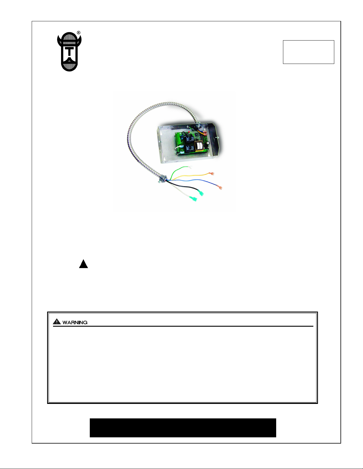
MODEL UC1
INSTALLATION INSTRUCTIONS
Recognize this symbol as an indication of important Safety Information!
!
OWNER INSTRUCTIONS, DO NOT DESTROY
THESE INSTRUCTIONS ARE INTENDED AS AN AID TO QUALIFIED, LICENSED
SERVICE PERSONNEL FOR PROPER INSTALLATION, ADJUSTMENT AND
OPERATION OF THIS PRODUCT. READ THESE INSTRUCTIONS THOROUGHLY
BEFORE ATTEMPTING INSTALLATION OR OPERATION. FAILURE TO FOLLOW
THESE INSTRUCTIONS MAY RESULT IN IMPROPER INSTALLATION, ADJUSTMENT, SERVICE OR MAINTENANCE POSSIBLY RESULTING IN FIRE, ELECTRICAL SHOCK, CARBON MONOXIDE POISONING, EXPLOSION, OR PERSONAL
INJURY OR PROPERTY DAMAGE.
DO NOT DESTROY. PLEASE READ CAREFULLY AND
KEEP IN A SAFE PLACE FOR FUTURE REFERENCE.
Copyright © 2003, Tjernlund Products, Inc. All rights reserved P/N 8504107
Page 3

Tjernlund Products welcomes your comments and questions. Address all correspondence to:
Customer Service • Tjernlund Products, Inc. • 1601 Ninth Street • White Bear Lake, MN 55110-6794
Call us toll free at 800-255-4208, visit our web site @ www.tjernlund.com or email us at fanmail@tjfans.com.
TABLE OF CONTENTS
Page (s)
Description and General Information...............................................................................................................................1
Installation Restrictions and Cautions ........................................................................................................................1, 2
UC1 Universal Control Board Features ..........................................................................................................................2
LED Status / Fault Indicators and Fault Retrieval from Memory .................................................................................2, 3
Pre / Post-Purge & Prover Status Check Settings.......................................................................................................3, 4
UC1 Installation ..............................................................................................................................................................4
Electrical Wiring
Specificatons, Warnings, Sequence of Operation & Internal Schematic .....................................................4, 5
Venter Ground, Motor and Prover Safety Circuit Connections ........................................................................6
Multiple and Milivolt Appliance interlocks .........................................................................................................6
Wiring to Gas Fired Appliance .................................................................................................................6, 7, 8
Wiring to Oil Fired Equipment ..............................................................................................................9, 10, 11
UC1 Operation and Draft Check .............................................................................................................................11, 12
Troubleshooting Electrical Problems.................................................................................................................12, 13, 14
Warranty & Replacement Parts.....................................................................................................................................14
DESCRIPTION
The UC1 is the new standard interlock control for Tjernlund's full line of Power Venters, Draft Inducers and Combustion Air
In-Forcers. It can be interlocked with virtually any burner control circuit. Features include: adjustable pre & post purge, LED status
/ diagnostic indicators, 10 second prover switch delay to avoid burner start up and wind induced short cycling. Interlocks with any
24-115 VAC burner control circuit and also includes “dry” contact actuation option. After each burner cycle the UC1 will continue
to operate in post-purge mode to allow the venter to purge the heater and vent of residual flue gases. A factory post-purge time is
set at 2 minutes and is adjustable up to 16 minutes, see “Pre / Post Purge and Prover Status Check Dip Switch Settings” on page 3.
GENERAL INFORMATION
Each UC1 is electrically factory line tested before shipment.
After opening carton, inspect thoroughly for hidden damage. If any damage is found notify freight carrier and your distributor
immediately and file a concealed damage claim.
Throughout the rest of this installation manual Venter will be synonymous with Power Venter, Draft Inducer or In-Forcer.
INSTALLATION RESTRICTIONS
1. The UC1 Prover Status Check is activated from the factory. When activated the UC1 Universal Control checks across the
P1 & P2 safety circuit Fan Prover to verify that the Fan Prover switch is “Open” upon a call for heat and not stuck “Closed”. See
“P1 & P2 Fan Prover Safety Circuit “Open” Upon Appliance Call”, page 4 for details.
2. A Venter post-purge on the UC1 has been factory set at 2 minutes. Confirm that dip switch #5 is in the up or "on" position. Oil
fired equipment requires that the post-purge be long enough to eliminate post cycle nozzle drip odor. A longer post-purge may
be necessary for longer vent runs or high heat retention, refractory lined combustion chambers. A shorter post-purge may be
desired for gas installations. If using the UC1 to control our combustion air In-Forcers a post-purge may not be desired. See “Pre /
Post Purge and Prover Status Check Dip Switch Settings”, page 3 for details.
3. The UC1 is intended for indoor installation only. Do not mount the UC1 on a heat source that exceeds 140oF (60oC).
Examples of improper mounting surfaces include vent pipe, top of heater casing or any place where radiant or convective heat
would cause the junction box temperature to exceed 140oF (60oC).
CAUTIONS
The UC1 must be installed by a qualified installer (an individual properly licensed and/or trained) in accordance with all local
codes or, in their absence, in accordance with the appropriate National Fire Protection Association #31, #54, #211 and the
National Electrical Code.
Failure to install, maintain and/or operate the UC1 in accordance with manufacturer's instructions may result in conditions
which can produce bodily injury and property damage.
1. The installer must verify that the BTU/hr. input of the appliance does not exceed the recommended input of the any Venter
being controlled by the UC1. Refer to the Venter, Inducer or In-Forcer installation instructions for capacities.
2. Disconnect power supply from the UC1 and heating equipment when making wiring connections and servicing the UC1.
Failure to do so may result in personal injury and/or equipment damage. LED #5 (RED) should be off with power removed.
1
Page 4
3.
All installation restrictions and instructions in the Venter, Inducer or In-Forcer installation instructions must be adhered to when
using the UC1.
4. Make certain power source is adequate for the UC1 and Venter requirements. Do not add equipment to a circuit when the total
electrical load is unknown.
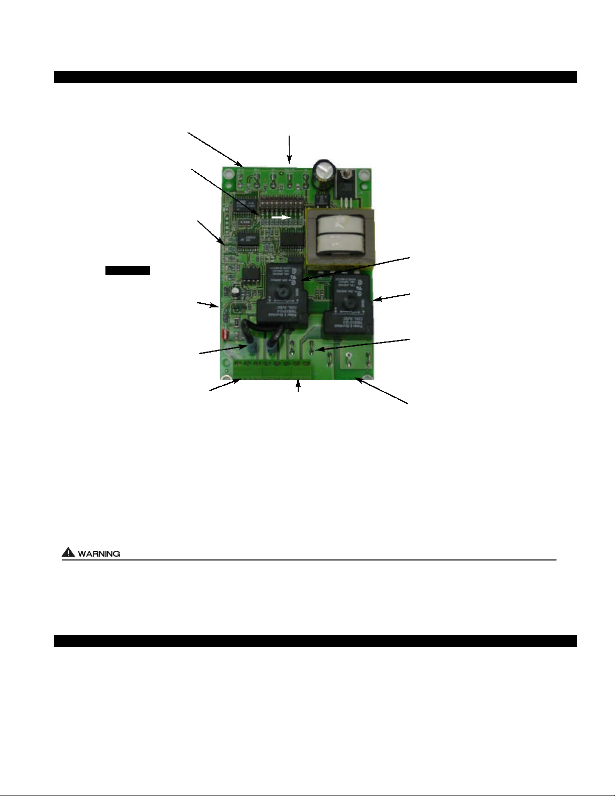
UC1 UNIVERSAL CONTROL BOARD FEATURES
P1 - P2 SAFETY CIRCUIT
TERMINALS
1 mA @ 5VDC.
SEE WARNING # 1.
DIP SWITCH SETTINGS
Pre-Purge (1-2)
Post-Purge (3-8)
Prover status check (9)
See “Pre / Post Purge &
Prover Status Check Dip
Switch Settings”.
LED STATUS LIGHTS
See “LED Status & Fault
Indicator Section” for details.
APPLIANCE CALL
VOLTAGE SELECTION
IMPORTANT
Place RED voltage jumper in
proper location based on
appliance call interlock voltage. SEE WARNING # 2.
J1- J2 CALL
JUMPER
Used when the call signal is
used as the “proven” return
signal to the appliance. See
wiring section for details.
APPLIANCE INTERLOCK
TERMINAL BLOCK (A-B, 1-4)
A - B - Dry Contact call. 3 mA @ 5VDC.
SEE WARNING # 1.
1 - 24 or 115 VAC intercepted call.
IMPORTANT: RED voltage jumper must
match intercepted call voltage.
2 - 24V common or 115V Neutral.
3 - Common terminal to appliance relay con-
tacts. IMPORTANT: J1-J2 jumper routes
call voltage at terminal 1 to 3. Remove
J1-J2 jumper if a different voltage source is
provided to terminal 3.
4 - Normally open terminal of appliance relay.
Will be energized from terminal 3 if safety
circuit is “proven”.
P1 P2 C GND F
LED 1 (AMBER)
LED 2 (GREEN)
LED 3 (GREEN)
LED 4 (RED)
LED 5 (RED)
DRY
24 V
115 V
A B 1 2 3 4 L N
C, GND, F AUXILIARY DEVICE
COMMUNICATION TERMINALS
2 mA @ 5VDC. For Tjernlund MAC1E or
MAC4E auxiliary devices. SEE WARNING # 1.
(1 9)
APPLIANCE
INTERLOCK
RELAY
J1 J2 XL XN
L / N - 115 VAC POWER
SUPPLY BLOCK
115 VAC / 50-60 Hz
Circuit protection provided by installer.
SEE WARNING # 3.
VENTER
MOTOR
RELAY
N M MTR
APPLIANCE INTERLOCK
RELAY
1 HP MAX LOAD across
terminals 3 & 4.
VENTER MOTOR RELAY
1 HP MAX LOAD from
terminals L to MTR & M.
XL / XN AUXILIARY DEVICE
POWER TERMINALS
115 VAC - Maximum of 0.15 Amps.
Only connect to Tjernlund auxiliary devices.
SEE WARNING # 1.
MTR & M / N LOAD TERMINALS
FROM VENTER MOTOR RELAY
Used to drive Venter Motor.
1 HP MAX LOAD across terminals MTR & M / N.
# 1. Power supplied by board. Do not supply power to this area or control damage may result.
# 2. Do not supply power to the appliance interlock block with the call selector in the “DRY” position.
Control damage may result if power is supplied.
# 3. Circuit protection must be provided by the installer. 16 Amps is the maximum current allowed for this device at terminal L.
A 15 Amp circuit breaker is recommended.
I
VETI
LED STATUS & FAULT INDICATORS
LED INDICATOR LIGHTS
LED #1 (Amber) Appliance call for heat.
LED #2 (Green) Safety circuit through P1 & P2 (Venter Fan Prover) is verified “Open” upon start-up. Indicates Venter prover is
closed during run cycle. Burner circuit is energized with contact closure from terminal 3 to 4.
LED #3 (Green) Power switched to Venter motor from L to MTR & M.
LED #4 (Red) Status / Fault indicator.
LED #5 (Red) 115 VAC power supplied to board. Also used as a status indicator.
2
Page 5
LED STATUS INDICATORS
LED #4 & #5 (Red) Flashing Alternately = Venter in Pre-purge. (Pre-Purge options 0, 5, 20, 35 seconds)
LED #4 & #5 (Red) Flashing in Unison = Venter in Post-Purge. (Post-Purge options 0, 30 seconds or 1, 2, 4, 8, 16 minutes)
LED #4 Flashes Continuously = Fan Prover opened for more than 10 seconds during burner cycle.
(Venter will run for 10 minutes, attempting to make Fan Prover)
LED FAULT INDICATORS
Fault conditions are indicated by counting the number of times LED #4 (Red) flashes.
LED #4 Flashes 2 Times Fan Prover was in electrically closed position prior to venter operation.
LED #4 Flashes 3 Times Fan Prover does not close within 60 seconds after call for heat.
LED #4 Flashes 4 Times Fan Prover did not re-close after 10 minutes of Venter operation.
LED #4 Flashes 5 Times Fan Prover opened for more than 10 seconds during burner cycle but closed within 10 minutes.
Investigate cause of Fan Prover short cycling such as; Firing burner at capacities or temperatures exceeding Venter limits, excessive vent pipe runs, elbows directly on venter discharge,
high winds, plugged / kinked Fan Prover sensing tube or a faulty Fan Prover switch. In-Forcer
model’s intake screen and prefilter, if applicable, should be cleaned if necessary.
IMPORTANT: Fault codes will automatically be displayed after a fault condition occurs. If the call for heat interlock signal or 115 VAC power is removed, the UC1 board will reset and the fault will be stored in memory instead of displayed.
Any new fault will replace any previous fault.
CHECKING MEMORY FOR LAST FAULT CODE
IMPORTANT: Prior to accessing the fault code memory, note the settings of the dip switches so that they can be returned to their
original Pre / Post-Purge positions. When power is supplied to the UC1 use caution when moving dip switches.
The last fault code can be retrieved at any time by setting all dip switches 1-8 to the up, or “on” position. The last fault code, or
lack there of, will be indicated by counting the number of times LED 4 flashes. By moving any of the dip switches back to their
original position, the fault code will be cleared. NOTE: The UC1 board must have its 115 VAC power supply present when any of
the (1-8) dip switches are moved back to their original position for the fault code to clear.
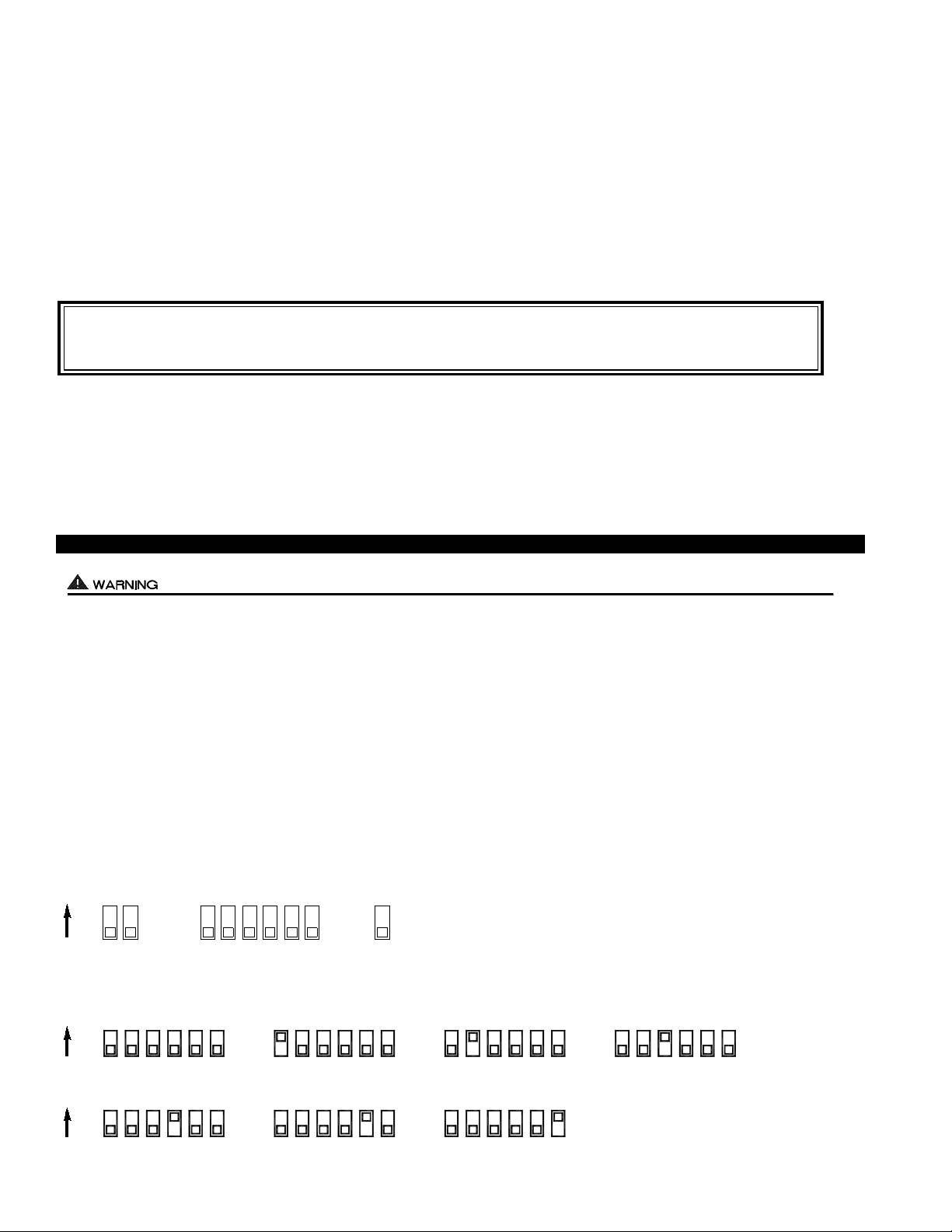
PRE / POST PURGE AND PROVER STATUS CHECK DIP SWITCH SETTINGS
Remove power to UC1 and heating equipment when installing, servicing or changing dip switch settings. Failure to do so may result in
personal injury and/or equipment damage. LED #5 (RED) should not be on if 115 VAC supply power is removed from the control.
Pre-purge
Used for a Venter with longer vent runs to get draft fully established throughout the vent system prior to burner ignition. Also beneficial for negative pressure prone environments. IMPORTANT: Nuisance equipment lockouts may occur if Venter pre-purge is running in conjunction with and is longer than any equipment timing circuit. Pre-purge settings must be shorter than burner control
lockout time unless wired prior to burner control timing circuit (i.e. aquastat / thermostat).
Post-purge
A Venter post-purge has been factory set at 2 minutes. Confirm that dip switch #5 is in the up or "on" position. Oil fired equipment
requires that the post-purge be long enough to eliminate post cycle nozzle drip odor. A longer post-purge may be necessary for
longer vent runs or high heat retention, refractory lined combustion chambers. A shorter post-purge may be desired for gas installations
or when using the UC1 to control a combustion air In-Forcer.
DIP SWITCH NUMBERING
Pre-Purge Post-Purge
1ON2 3 4 5 6 7 8 9
Prover Status
Check Activated
POST-PURGE SETTINGS (SEE “POST-PURGE” ABOVE PRIOR TO SETTING)
3
ON
ON
4
43 4865 7 3 5 6 7 8 3 4 5 6 7 8
4 Minutes 8 Minutes 16 Minutes
865 7 3 5 6 7 8 3
4
5 6 7 8 3 7546 8
4
1 Minute0 Seconds 30 Seconds 2 Minutes
3
Page 6

ON
PRE-PURGE SETTINGS
(SEE “PRE-PURGE” ON PAGE 3 PRIOR TO SETTING PRE-PURGE)
1 2 1 2 1 2 1 2
0 Seconds 5 Seconds 20 Seconds 35 Seconds
P1 & P2 FAN PROVER SAFETY CIRCUIT “OPEN” UPON APPLIANCE CALL
Prover Status
Check Activated
The Prover Status Check is activated from the factory. When activated the UC1 Universal Control
checks across P1 & P2 safety circuit (Fan Prover) to verify that the Fan Prover switch is “Open”
upon a call for heat and not stuck “Closed”. IMPORTANT: This must always be in the down
9
“Activated” position when side wall venting. When using the PS1505 Fan Prover in conjunction with a draft inducer on a vertical termination stack, “natural draft” may be sufficient to keep
Prover contacts closed prior to a call for heat by an interlocked appliance. This is the only condition where this safety feature should be deactivated. Push up or “ON” to deactivate.
UC1 INSTALLATION
Do not mount the UC1 junction box on a heat source that exceeds 140oF (60oC). Examples of improper mounting surfaces
include vent pipe, top of heater casing or any place where radiant or convective heat would cause the junction box temperature to
exceed 140oF. The UC1 is intended for indoor installation only.
Using the key hole slots on the back of the UC1 junction box as a template, mark 4 holes on the mounting surface, drill pilot holes
if necessary, and secure junction box using provided screws.
The UC1 has a 2 foot whip that contains a ground lead and the leads to power the Venter motor and connect to the Fan Prover. If
it is desirable to mount the UC1 more than 2 feet from the Fan Proving Switch an additional electrical junction box and appropriate
length of conduit will be necessary. Any added wire should be 14 gage and a pig tail should be added to each ground wire connection so that each electrical junction box is grounded. See diagram below for a typical UC1, Fan Prover and Venter installation.
TYPICAL UC1, FAN PROVER AND VENTER INSTALLATION
ALUMINUM SENSING TUBE, 4 FT. MAXIMUM LENGTH
2 FT. MAXIMUM LENGTH UNLESS ADDITIONAL
INSTALLER-SUPPLIED
BURNER INTERLOCK
CONNECTION
CONDUIT AND J-BOX ARE ADDED
INSTALLER-SUPPLIED
115 VAC CONNECTION
POWER
REQUIREMENTS
ADD VENTER MOTOR
LOAD PLUS 1/2 AMP
FOR UC1 LOAD
EXTERNAL
POWER SWITCHING
CAPACITY
EXTERNAL
CALL TRIGGER
METHODS
J1 / J2
JUMPER
SAFETY
CIRCUIT
UC1
T-BLOCK
L / N
XL / XN
UC1 CONTROL
M & MTR
(RELAY K2)
T-BLOCK
3 TO 4
(RELAY K1)
T-BLOCK
A / B
OR
24V
1 / 2
OR
115V
1 / 2
J1 / J2
P1 / P2
FAN PROVER
INSTALLER-SUPPLIED CONDUIT
AND 3 WIRE, MINIMUM 14 GAGE
VENTER
ELECTRICAL WIRING
ELECTRICAL SPECIFICATIONS
120 VAC ±10 %, 50/60 Hz
CIRCUIT PROTECTION PROVIDED BY INSTALLER
150 mA MAX @ 120 VAC, 50/60 Hz
CAN ONLY BE CONNECTED TO TJERNLUND-SPECIFIED AUXILIARY DEVICE
DURING OPERATION THE CONTROL USES 50 mA MAX @ 120 VAC
MOTOR - 1 H.P. MAX. @ 120 VAC, 50/60 Hz
GENERAL PURPOSE - 15A @ 120 VAC, 50/60 Hz
MOTOR - 1 H.P. MAX. @ 120 VAC, 50/60 Hz
GENERAL PURPOSE - 15A @ 120 VAC, 50/60 Hz
RESISTIVE - 10A @ 28 VDC PILOT DUTY - 470 VA
USER-PROVIDED CONTACT CLOSURE FROM A TO B. SIZE CONTACT CLOSURE TO HANDLE
3 mA @ 5 VDC. MOVE RED VOLTAGE JUMPER TO "DRY" LOCATION. DO NOT SUPPLY POWER.
USER-PROVIDED 24 VAC AT TERMINALS 1 & 2. 1 = CALL HOT, 2 = COMMON. CONTROL
REQUIRES 5 mA @ 24 VAC TO TRIGGER. MOVE RED VOLTAGE JUMPER TO "24V" LOCATION.
USER-PROVIDED 115 VAC AT TERMINALS 1 & 2. 1 = CALL LINE, 2 = NEUTRAL. CONTROL
REQUIRES 1 mA @ 115 VAC TO TRIGGER. MOVE RED VOLTAGE JUMPER TO "115V" LOCATION.
USED TO JUMP CALL HOT (24 VAC) OR CALL LINE (115 VAC) FROM TERMINAL 1 TO TERMINAL 3.
REMOVE J1-J2 JUMPER IF A DIFFERENT VOLTAGE SOURCE IS PROVIDED TO TERMINAL 3.
CONNECTED TO FAN PROVER.
1 mA @ 5 VDC. DO NOT SUPPLY POWER HERE.
4
Page 7

All wiring from the UC1 to the appliance must be appropriate Class 1 wiring as follows: installed in rigid metal conduit, intermediate
metal conduit, rigid non-metallic conduit, electrical metallic tubing, Type MI Cable, Type MC Cable, or be otherwise suitably protected
from physical damage.
IMPORTANT: MORE THAN ONE INTERLOCK METHOD MAY BE APPLICABLE
In many cases it is easier to interlock with the thermostat/aquastat portion of the heater control circuit vs. the ignition module /
primary control portion of the heater control circuit. Review all of the wiring diagram options prior to choosing the best method.
SEQUENCE OF OPERATION WITH UC1 UNIVERSAL CONTROL AND 24 VAC OR 115 VAC HEATER CONTROL CIRCUIT:
Control signal from thermostat, aquastat, primary control or gas valve is intercepted and routed to terminal “1” on UC1 terminal
strip. When terminal “1” is energized with either 24 VAC or 115 VAC, the Venter motor is energized. After draft is established, the
Fan Proving Switch closes within 5 to 10 seconds energizing terminal “4”, which completes the circuit allowing burner to fire.
NOTE: If a Venter pre-purge is selected, the burner will not fire until the pre-purge time is finished. The Venter will continue to run
after the burner has finished firing for the set post-purge time cycle. The UC1 is set for a 2 minute post-purge time period from the
factory. See “Pre / Post-Purge Settings” on page 3 for details.
The "1" input terminal on the UC1 can accept either a 24 VAC or 115 VAC control signal. IMPORTANT: The RED voltage
jumper must be positioned based on appliance interlock voltage 24V or 115V. If using the “DRY” contact activation method, use
terminals A & B on UC1 control and position the RED voltage jumper tab in the “DRY” position. See millivolt appliance interlock
diagram for further information. IMPORTANT: Only one interlock method (i.e. 24V, 115V or “Dry”) can be used with the UC1.
Multiple appliance interlocks require the use of our MAC-Series multiple appliance controls.
The steps listed under each diagram are intended as a supplement to the diagram. Wiring colors or designations may vary by
manufacturer. If you are unable to wire the UC1 as outlined in these instructions, call Tjernlund’s Customer Service Department
toll free at 1-800-255-4208 for assistance.
IMPORTANT: If the call for heat interlock signal or 115 VAC power is removed, the UC1 board will reset and any fault, if present,
will be stored in memory instead of displayed. See page 3, “Checking Memory for Last Fault Code”.
UC1 UNIVERSAL CONTROL WIRING SCHEMATIC
The Ground lead, Venter motor and Fan Prover leads are factory connected to the UC1 circuit board. Venter Ground, motor and
Fan Prover wiring connections are made at the free end of the 2 foot whip.
LEGEND:
DO NOT SUPPLY VOLTAGE
USER-PROVIDED
CALL SWITCH
"DRY"
LINE
115 VAC
OR
24 VAC
COMMONNEUTRAL
APPROVED
SUPPLY
115 VAC
50/60 Hz
MOTOR
1 H.P. MAX @ 115 VAC
TO "A" OR "B".
OR
HOT
115 VAC
24 VAC
5 VDC BOARD-GENERATED POWER
DO NOT SUPPLY POWER!
IMPORTANT:
RED JUMPER POSITION MUST BE THE SAME
AS APPLIANCE INTERLOCK VOLTAGE.
115V
24V
DRY
CALL
J2
J1
JUMPER
COM
INTERLOCK
RELAY
NO
COM
R
TJERNLUND
PRODUCTS,
INC.
XL
XN
N
9183006
MOTOR
MTRM
NO
RELAY
LED5 LED4 LED2LED3
RED
K1
K2
RED
LED1
GREEN
GREEN
AMBER
PRE-PURGE SETTINGS
POST-PURGE SETTINGS
OPEN PROVER OPTION
115 OR 24 VAC FROM CALL JUMPER
OR USER-PROVIDED VOLTAGE
FROM TERMINAL 3 TO 4 WITH CALL
JUMPER REMOVED
ON
(1 - 2)
(3 - 8)
(9)
2 431
CP1P2
5
97 86
FGND
PROVER
FOR TJERNLUND
MAC1E OR MAC4E
AUXILIARY
DEVICES. DO NOT
CONNECT POWER
TO P1, P2, C, GND
OR F. DOING SO
WILL DAMAGE THE
CONTROL.
D/N 1303958-1
WARNING: Disconnect power supply from the UC1 and heating equipment when making wiring connections and servicing the
Venter. Failure to do so may result in personal injury and/or equipment damage. LED #5 (RED) should be off with
power removed.
5
Page 8

RED JUMPER POSITION MUST BE THE SAME
VENTER GROUND, MOTOR AND PROVER SAFETY CIRCUIT CONNECTIONS
VENTER PROVER CONNECTIONS
Blue and Yellow leads from UC1 whip (P1 and P2) safety circuit must be connected to a Fan Prover switch. Leads are not polarity
sensitive. If using a Draft Inducer and venting only millivolt appliances, the PS1505 Fan Prover is not needed. See WHKE
instructions or consult factory.
1 UNIVERSAL
VENTER MOTOR CONNECTIONS
Connect Black and White motor leads from UC1 whip to Venter motor leads. Venter motor must not exceed 1 h.p. Make sure
venter motor is wired for proper rotation. Consult motor nameplate for rotation.
VENTER GROUND CONNECTION
Connect Green ground lead from UC1 whip to Fan Prover ground screw along with ground from Venter motor. If using a Draft
Inducer and venting only millivolt appliances where the PS1505 Fan Prover is not needed, connect ground to Venter motor ground.
MULTIPLE APPLIANCE INTERLOCKS
To interlock with one additional 24/115 VAC heater add the MAC1E. It is a stripped down auxiliary board version of the UC1 and
is powered by and communicates with the UC1 through a factory wired whip.
To interlock more than two 24/115 VAC heaters, add the MAC4E for a total of up to 5 heaters. It is powered by and communicates
with the UC1 through a factory wired whip. Consult factory for installations with more than 5 heaters.
To interlock a millivolt water heater and a 24/115 VAC furnace or boiler, add the WHKE and MAC1E.
MILLIVOLT HEATER INSTALLATIONS
Each millivolt appliance interlocked with the UC1 must have its own WHKE kit installed. The WHKE Gas Pressure Switch actuates
the Venter through the A - B Dry contacts. The Linear Limit switch disables the heater in the event of a venting malfunction.
IMPORTANT: Each millivolt appliance interlocked with the UC1 must have its own Linear Limit spill switch.
MULTIPLE MILLIVOLT HEATER INSTALLATIONS
Multiple millivolt heaters can be installed by using the A-B dry contact terminals of the UC1, MAC1E or MAC4E. Wire each WHKE
gas pressure switch in parallel across A-B terminals of UC1, MAC1E or MAC4E. Wire Linear Limit safety switch into each individual millivolt heater. For further information consult factory or WHKE instructions.
UC1 BURNER INTERLOCK WIRING DIAGRAMS
UC1 UNIVERSAL CONTROL CONNECTED WITH A 24 VAC ELECTRONIC IGNITION MODULE
AS APPLIANCE INTERLOCK VOLTAGE.
SPARK (9)
(8)
(7)
24V (6)
24V GND (5)
BNR GND (4)
PV (3)
MV / PV (2)
MV (1)
HONEYWELL IGNITION
CONTROL
OR
PI
YE
GR
YE
WH
OR
YE
PV
WH
PV
MV
OR
MV
GR
GAS VALVE
SUPPLY
115 VAC
50/60 Hz
GROUND
IMPORTANT:
CRIMP GROUND WIRE TO GROUNDING
SPADE TERMINAL IN ELECTRICAL BOX.
R
115V
UNIVERSAL CONTROLLER
J1J2
XL
XN
DRY
24V
CALL
JUMPER
LEGEND:
115 VAC
24 VAC
D/N 9183046-8
1. Remove the wire on MV at gas valve and connect it on #1 on UC1 terminal block.
2. Connect #2 on UC1 terminal block to MV/PV.
3. Connect #4 on UC1 terminal block to MV on gas valve.
4. Make sure RED voltage jumper on UC1 is on 24V.
5. Connect 115 VAC supply voltage to L & N terminals on UC1. Crimp Ground wire to grounding spade terminal in UC1.
Important: Installer must supply overload and disconnect protection.
6. If not previously completed, connect ground from UC1 whip to Venter ground. Connect Black and White leads from UC1 whip
to Venter motor leads. Connect Blue and Yellow leads from UC1 whip to Fan Prover switch. Prover Leads are not polarity sensitive.
6
Page 9

UC1 UNIVERSAL CONTROL CONNECTED WITH A SINGLE ZONE 24 VAC THERMOSTAT
RED JUMPER POSITION MUST BE THE SAME
IMPORTANT:
AS APPLIANCE INTERLOCK VOLTAGE.
THERMOSTAT
115V
24V
DRY
Y
R
R
C
Y
W
INTERNAL CONTROL
OF FURNACE
IMPORTANT:
W
GG
SUPPLY
115 VAC
50/60 Hz
GROUND
J1J2
XL
R
XN
CALL
JUMPER
UNIVERSAL CONTROLLER
LEGEND:
115 VAC
24 VAC
D/N 9183046-5
CRIMP GROUND WIRE TO GROUNDING
SPADE TERMINAL IN ELECTRICAL BOX.
1. Connect W from t-stat to #1 on terminal block of UC1.
2. Connect #2 on UC1 terminal block to C on internal control terminal strip of furnace/boiler.
3. Connect #4 on UC1 terminal block to W on internal control terminal strip of furnace/boiler.
4. Make sure RED voltage jumper on UC1 is on 24V.
5. Connect 115 VAC supply voltage to L & N terminals on UC1. Crimp Ground wire to grounding spade terminal in UC1.
Important: Installer must supply overload and disconnect protection.
6. If not previously completed, connect ground from UC1 whip to Venter ground. Connect Black and White leads from UC1 whip
to Venter motor leads. Connect Blue and Yellow leads from UC1 whip to Fan Prover switch. Prover Leads are not polarity sensitive.
NOTE: If burner safety control goes out on lockout, the Venter will continue to run as long as a call for heat is present.
UC1 UNIVERSAL CONTROL CONNECTED WITH A 24 OR 115 VAC STANDING PILOT
IMPORTANT:
RED JUMPER POSITION MUST BE THE SAME
INTERNAL CONTROLS
OF FURNACE/BOILER
B2
COM
COM
TR
24V OR 115V GAS VALVE
Aquastat
T-stat
HOT
TH
B1
HOT
SUPPLY
115 VAC
50/60 Hz
GROUND
IMPORTANT:
CRIMP GROUND WIRE TO GROUNDING
SPADE TERMINAL IN ELECTRICAL BOX.
J1J2
XL
XN
1. Remove the wire on TH or HOT of gas valve and connect it on #1 on UC1 terminal block.
2. Connect #2 on UC1 terminal block to TR or Common.
3. Connect #4 on UC1 terminal block to TH or HOT on gas valve.
4. Make sure RED voltage jumper on UC1 is on 24V or 115V depending on control voltage.
5. Connect 115 VAC supply voltage to L & N terminals on UC1. Crimp Ground wire to grounding spade terminal in UC1.
Important: Installer must supply overload and disconnect protection.
6. If not previously completed, connect ground from UC1 whip to Venter ground. Connect Black and White leads from UC1 whip
to Venter motor leads. Connect Blue and Yellow leads from UC1 whip to Fan Prover switch. Prover Leads are not polarity sensitive.
AS APPLIANCE INTERLOCK VOLTAGE.
115V
UNIVERSAL CONTROLLER
DRY
24V
CALL
JUMPER
LEGEND:
115 VAC
24 OR 115 VAC
D/N 9183046-1
7
Page 10

UC1 UNIVERSAL CONTROL AND WHKE INTERLOCK KIT
CONNECTED WITH A MILLIVOLT APPLIANCE
R
IMPORTANT:
115V
UNIVERSAL CONTROLLER
J1J2
XL
XN
RED JUMPER POSITION MUST BE THE SAME
AS APPLIANCE INTERLOCK VOLTAGE.
WHKE GAS
PRESSURE
SWITCH
SUPPLY
115 VAC
50/60 Hz
GROUND
DRY
24V
CALL
JUMPER
LINEAR LIMIT
SPILL SWITCH
950-0470 (JA1)
THERMOCOUPLE
JUNCTION ADAPTER
GAS
VALVE
LEGEND:
115 VAC
5 VDC
BOARDGENERATED
POWER.
DO NOT
SUPPLY
POWER!
MILLIVOLT
D/N 9183046-9
IMPORTANT:
CRIMP GROUND WIRE TO GROUNDING SPADE TERMINAL IN
ELECTRICAL BOX.
SAFETY CIRCUIT ACROSS P1 & P2 OF UC1 IS NOT UTILIZED
IN THIS APPLICATION. SPILL SWITCH MUST BE INTERLOCKED
WITH HEATING EQUIPMENT AS SHOWN.
30 MILLIVOLT WATER HEATERS REQUIRE USE OF THE
950-0470 THERMOCOUPLE JUNCTION ADAPTER.
ON 750 MILLIVOLT (POWER PILE) WATER HEATERS WIRE
LINEAR LIMIT SPILL SWITCH IN SERIES WITH HIGH LIMIT
(ECO) OF WATER HEATER. LINEAR LIMIT SPILL SWITCH,
950-0470 JUNCTION ADAPTER AND GAS PRESSURE
SWITCH ARE INCLUDED WITH WHKE KIT.
Each millivolt appliance interlocked with the UC1 must have its own WHKE kit installed. The WHKE Gas Pressure Switch actuates
the Venter through the A - B Dry contacts. The Linear Limit switch disables the heater in the event of a venting malfunction.
IMPORTANT: Each millivolt appliance interlocked with the UC1 must have its own Linear Limit spill switch.
1. Wire WHKE Gas Pressure Switch in series with A and B terminal on UC1. Do not supply voltage to A and B terminals.
2. Wire WHKE Linear Limit in series with thermocouple junction adapter or high limit ECO of water heater.
3. Make sure RED voltage jumper on UC1 is in the DRY position.
4. Connect 115 VAC supply voltage to L & N terminals on UC1. Crimp Ground wire to grounding spade terminal in UC1.
Important: Installer must supply overload and disconnect protection.
5. If not previously completed, connect ground from UC1 whip to Venter ground. Connect Black and White leads from UC1 whip
to Venter motor leads. Connect Blue and Yellow leads from UC1 whip to Fan Prover switch. Prover Leads are not polarity sensitive.
If using a Draft Inducer and only venting millivolt appliances the PS1505 Fan Proving Switch is not necessary, see WHKE
instructions for complete details.
UC1 UNIVERSAL CONTROL CONNECTED TO A GAS OR OIL BURNER WITH AN AQUASTAT
IMPORTANT:
R
J1J2
XL
XN
AQUASTAT
C1
L1
C2
L2
B1
B2
N
L1
LINE VOLTAGE OIL BURNER
PRIMARY CONTROL, BURNER
RELAY OR GAS VALVE
IMPORTANT:
CRIMP GROUND WIRE TO GROUNDING
SPADE TERMINAL IN ELECTRICAL BOX.
RED JUMPER POSITION MUST BE THE SAME
AS APPLIANCE INTERLOCK VOLTAGE.
SUPPLY
115 VAC
50/60 Hz
GROUND
1. Disconnect B1 from L1 of oil burner primary control, burner relay or hot of gas valve and reconnect to #1 on UC1 terminal block.
2. Connect #2 on UC1 terminal block to B2 or N.
3. Connect #4 on UC1 terminal block to the L1 on line voltage oil burner primary control, burner relay or gas valve.
4. Make sure RED voltage jumper on UC1 is on 115V.
5. Connect 115 VAC supply voltage to L & N terminals on UC1. Crimp Ground wire to grounding spade terminal in UC1.
Important: Installer must supply overload and disconnect protection.
6. If not previously completed, connect ground from UC1 whip to Venter ground. Connect Black and White leads from UC1 whip
to Venter motor leads. Connect Blue and Yellow leads from UC1 whip to Fan Prover switch. Prover Leads are not polarity sensitive.
NOTE: If burner safety control goes out on lockout, the Venter will continue to run as long as a call for heat is present.
8
LEGEND:
115 VAC
115V
UNIVERSAL CONTROLLER
DRY
24V
CALL
JUMPER
D/N 9183046-7
Page 11

UC1 UNIVERSAL CONTROL CONNECTED TO A HONEYWELL R7184 SERIES OR EQUIVALENT
PRIMARY CONTROL WITH A LINE VOLTAGE THERMOSTAT OR AQUASTAT
SUPPLY
Limit
115 VAC
60 Hz
SUPPLY
115 VAC
50/60 Hz
GROUND
LEGEND:
115 VAC
D/N 9183046-6
IMPORTANT:
RED JUMPER POSITION MUST BE THE SAME
AS APPLIANCE INTERLOCK VOLTAGE.
115V
DRY
24V
CALL
JUMPER
UNIVERSAL CONTROLLER
J1J2
XL
XN
R
R7184
L1
T
Low Voltage
Jumper
Alarm
Limit
L2
T
Oil Valve
Burner
Motor
Interrupted
Ignitor
Intermittant
A
Cad Cell
A
Line Voltage Thermostat
or Aquastat Control
OIL VALVE
BURNER MOTOR
IGNITION TRANS
IMPORTANT:
CRIMP GROUND WIRE TO GROUNDING
SPADE TERMINAL IN ELECTRICAL BOX.
1. Disconnect burner motor wire off the R7184.
2. Connect burner motor terminal of R7184 to #1 on UC1 terminal block.
3. Connect #2 on UC1 terminal block to L2 or N.
4. Connect #4 on UC1 terminal block to burner motor wire removed from R7184.
5. Make sure RED voltage jumper on UC1 is on 115V.
6. Connect 115 VAC supply voltage to L & N terminals on UC1. Crimp Ground wire to grounding spade terminal in UC1.
Important: Installer must supply overload and disconnect protection.
7. If not previously completed, connect ground from UC1 whip to Venter ground. Connect Black and White leads from UC1 whip
to Venter motor leads. Connect Blue and Yellow leads from UC1 whip to Fan Prover switch. Prover Leads are not polarity sensitive.
UC1 UNIVERSAL CONTROL CONNECTED WITH A CARLIN 40200, 42230, 48245, 50200, 60200
SERIES OR EQUIVALENT AND A LINE VOLTAGE THERMOSTAT OR AQUASTAT
SUPPLY
115 VAC
60 Hz
Red/WhiteT
Low Voltage
Jumper
T Black
F White
OrangeF
A Blue
Alarm
A Violet
1. Disconnect burner motor wire off the Orange on Carlin.
2. Connect burner motor terminal Orange of Carlin to #1 on UC1 terminal block.
3. Connect #2 on UC1 terminal block to L2 or N
4. Connect #4 on UC1 terminal block to burner motor wire removed from Orange of Carlin.
5. Make sure RED voltage jumper on UC1 is on 115V.
6. Connect 115 VAC supply voltage to L & N terminals on UC1. Crimp Ground wire to grounding spade terminal in UC1.
Important: Installer must supply overload and disconnect protection.
7. If not previously completed, connect ground from UC1 whip to Venter ground. Connect Black and White leads from UC1 whip
to Venter motor leads. Connect Blue and Yellow leads from UC1 whip to Fan Prover switch. Prover Leads are not polarity sensitive.
Line Voltage Thermostat
or Aquastat Control
10 FLA / 60 LRA
500 VA
0.3 A, AC
IMPORTANT:
CRIMP GROUND WIRE TO GROUNDING
SPADE TERMINAL IN ELECTRICAL BOX.
Limit
BURNER MOTOR
IGNITION TRANS
OIL VALVE
SUPPLY
115 VAC
50/60 Hz
GROUND
IMPORTANT:
RED JUMPER POSITION MUST BE THE SAME
AS APPLIANCE INTERLOCK VOLTAGE.
115V
DRY
24V
CALL
J2
J1
XNXL
R
JUMPER
UNIVERSAL CONTROLLER
LEGEND:
115 VAC
D/N 9183046-3
9
Page 12

UC1 UNIVERSAL CONTROL CONNECTED TO AN OIL-FIRED FURNACE WITH A
HONEYWELL T87 OR EQUIVALENT NON-POWERED THERMOSTAT
RED JUMPER POSITION MUST BE THE SAME
AS APPLIANCE INTERLOCK VOLTAGE.
IMPORTANT:
FACTORY-
WIRED
HONEYWELL T87 OR EQUIVALENT
NON-POWERED THERMOSTAT
PRIMARY CONTROL
BLACK
ORANGE
WHITE
HONEYWELL
R8184 SERIES
OR EQUIVALENT
T
B
T
O
F
W
F
IMPORTANT:
CRIMP GROUND WIRE TO GROUNDING
SPADE TERMINAL IN ELECTRICAL BOX.
SUPPLY
115 VAC
50/60 Hz
GROUND
115V
UNIVERSAL CONTROLLER
J1J2
XL
R
XN
24V
DRY
IMPORTANT:
REMOVE JUMPER TO AVOID
BACKFEEDS OR SHORT
CIRCUITS.
LEGEND:
115 VAC
LOW VAC
5 VDC BOARD-GENERATED
POWER.
DO NOT SUPPLY POWER!
D/N 9183047-1
1. IMPORTANT: Remove J1 & J2 Call Jumper on UC1 to avoid backfeeds or short circuits.
2. Connect T87 or Equivalent non-powered thermostat to A and B terminals on UC1.
3. Remove T T Jumper from R8184 or equivalent Primary Control.
4. Connect #3 on UC1 terminal block to T terminal of Primary Control.
5. Connect #4 on UC1 terminal block to remaining T terminal of Primary Control.
6. Make sure RED voltage jumper on UC1 is on DRY.
7. Connect 115 VAC supply voltage to L & N terminals on UC1. Crimp Ground wire to grounding spade terminal in UC1.
Important: Installer must supply overload and disconnect protection.
8. If not previously completed, connect ground from UC1 whip to Venter ground. Connect Black and White leads from UC1 whip
to Venter motor leads. Connect Blue and Yellow leads from UC1 whip to Fan Prover switch. Prover Leads are not polarity sensitive.
NOTE: If burner safety control goes out on lockout, the Venter will continue to run as long as a call for heat is present.
UC1 UNIVERSAL CONTROL CONNECTED TO A HONEYWELL
R8184 SERIES OR EQUIVALENT PRIMARY CONTROL
L1
RED JUMPER POSITION MUST BE THE SAME
AS APPLIANCE INTERLOCK VOLTAGE.
IGNITION TRANS
BLACK
SUPPLY
BURNER MOTOR
IMPORTANT:
CRIMP GROUND WIRE TO GROUNDING
SPADE TERMINAL IN ELECTRICAL BOX.
115 VAC
50/60 Hz
GROUND
HONEYWELL
R8184 SERIES
OR EQUIVALENT
LEGEND:
115 VAC
BLACK
ORANGE
WHITE
WHITE
WHITE
D/N 9183046-2
1. Separate the Black burner motor wire from the Orange wire of R8184 Primary Control.
NOTE: Do not separate the ignition transformer wire from the Orange.
2. Connect Orange wire of R8184 to #1 on UC1 terminal block.
3. Connect #2 on UC1 terminal block to White on R8184.
4. Connect Black of burner motor to #4 on UC1 terminal block.
5. Make sure RED voltage jumper on UC1 is on 115V.
6. Connect 115 VAC supply voltage to L & N terminals on UC1. Crimp Ground wire to grounding spade terminal in UC1.
Important: Installer must supply overload and disconnect protection.
7. If not previously completed, connect ground from UC1 whip to Venter ground. Connect Black and White leads from UC1 whip
to Venter motor leads. Connect Blue and Yellow leads from UC1 whip to Fan Prover switch. Prover Leads are not polarity sensitive.
IMPORTANT:
R
115V
J2
UNIVERSAL CONTROLLER
J1
XL
XN
DRY
24V
CALL
JUMPER
10
Page 13

UC1 UNIVERSAL CONTROL CONNECTED WITH A HONEYWELL R8184 SERIES
OR EQUIVALENT PRIMARY CONTROL AND A BURNER MOTOR POST-PURGE
BURNER
L1
BLACK
ORANGE
IGNITION
TRANS
B
O
WHITE
W
HONEYWELL R8184
SERIES OR EQUIVALENT
OIL VALVE
VENTER
MOTORMOTOR
THERMOSTAT
T
T
F
F
SUPPLY
115 VAC
50/60 Hz
GROUND
J1J2
XL
XN
N MTRM
IMPORTANT:
RED JUMPER POSITION MUST BE THE SAME
AS APPLIANCE INTERLOCK VOLTAGE.
115V
DRY
24V
CALL
JUMPER
UNIVERSAL CONTROL
IMPORTANT:
CRIMP GROUND WIRE TO GROUNDING
SPADE TERMINAL IN ELECTRICAL BOX.
LEGEND:
115 VAC
D/N 9183047-4
1. Separate the burner motor wire and ignition transformer from the Orange wire of R8184.
2. Connect the Orange of R8184 to #1 on UC1 terminal block.
3. Connect #2 on UC1 terminal block to White on R8184 or N.
4. Connect the HOT wire of oil solenoid valve to #4 on UC1 terminal block and neutral wire to White or N.
5. Connect burner motor and ignition transformer HOT wires to M terminal on UC1 and neutrals to White or N.
6. Make sure RED voltage jumper on UC1 is on 115V.
7. Connect 115 VAC supply voltage to L & N terminals on UC1. Crimp Ground wire to grounding spade terminal in UC1.
Important: Installer must supply overload and disconnect protection.
8. If not previously completed, connect ground from UC1 whip to Venter ground. Connect Black and White leads from UC1 whip
to Venter motor leads. Connect Blue and Yellow leads from UC1 whip to Fan Prover switch. Prover Leads are not polarity sensitive.
UC1 UNIVERSAL CONTROL OPERATIONAL CHECK
1. Confirm power is supplied to the Control. LED #5 (RED) should be on.
2. Activate the UC1 by initiating an appliance call for heat. LED #1 (AMBER) should be on.
3. The motor relay will close and activate the Venter motor. LED #3 (GREEN) should be on.
ON
4. If the safety circuit across P1 & P2 (Venter Prover) is closed, indicating an approved condition,
the appliance interlock relay will close making terminal #3 closed to terminal #4 & LED #2
(GREEN). Appliance burner should fire.
5. Remove power to the UC1 and any interlocked appliances. The LED #5 (RED) or any LED’s
should not be on. Test the safety circuit by removing the Blue or Yellow Lead from Fan Proving
Switch. Do not let the opened LEAD touch a ground or damage may occur to the control when
power is Reestablished. Reestablish power to the UC1 and interlocked appliances and initiate
a call for heat. After 60 seconds a Prover Start Up fault should arise with LED #4 flashing 3 times.
6. Remove appliance call for heat and power to the UC1 and any interlocked appliances. The LED
#5 (RED) or any LED’s should not be on. Reconnect Blue or Yellow Fan Prover lead to Fan
Proving Switch terminal removed from in step 5.
7. Reestablish power to UC1 and interlocked appliances and initiate a call for heat to confirm proper operation of UC1 and
appliance.
RESETTING FAULT CODE CREATED BY STEP 5 OF OPERATIONAL CHECK
IMPORTANT: Prior to accessing the fault code memory, note the settings of the dip switches so that they can be returned to their
original Pre / Post-Purge positions. When power is supplied to the UC1 use caution when moving dip switches.
The last fault code can be retrieved at any time by setting all dip switches 1-8 to the up, or “on” position. The last fault code, or
lack there of, will be indicated by counting the number of times LED 4 flashes. By moving any of the dip switches back to their
original position, the fault code will be cleared. NOTE: The UC1 board must have its 115 VAC power supply present when any of
the (1-8) dip switches are moved back to their original position for the fault code to clear.
11
Page 14

OPERATION AND DRAFT CHECK
The installer must perform Draft Check, Safety Interlock and Combustion Air Test as outlined in the Venter installation manual. If
Venter installation manual is not present use the following procedure below.
The Fan Proving Switch is designed to disable the appliance gas valve or
burner motor upon Venter failure only! It is not designed and cannot replace,
regular vent system inspection, appliance servicing and combustion testing.
1. Close all doors and windows of the building. If the appliance is installed in a
utility room or closet, close the entrance door to this room. Close fireplace
dampers.
2. Turn on clothes dryer and all exhaust fans such as range hoods, bathroom
PROPER
DRAFT
ESTABLISHED
PROPER
DRAFT
ESTABLISHED
exhausts and whole house fans to maximum speeds. Do not operate a fan
used strictly for Summer exhausting.
3. Following the appliance manufacturer’s instructions, place the appliance in
operation, set thermostat for continuous operation.
4. Verify that Venter operates first, prior to burner ignition. Watch to make sure burner lights off properly.
GAS
After allowing appliance(s) to operate for 15 minutes, follow the appliance manufacturers instructions to verify that the recommended draft is present. In general, most gas appliances will operate safely with flue outlet draft levels from -0.02 to -0.05" W.C..
If the draft is excessive, make necessary adjustments to the barometric control and/or follow the, “Venter Air Flow Damper
Adjustment” procedure outlined in Venter installation manual. As a cross check, a candle or match can be held adjacent to the
draft hood or barometric control to verify flame/smoke is being drawn into, and not rolling out of edge of the relief opening, (See
Diagram above). If exhaust gases are escaping from the relief opening of the draft hood or barometric control, the equipment
should not be operated until proper adjustments or repairs are made to provide adequate draft levels.
OIL
After allowing equipment to operate for 15 minutes, make necessary adjustments to the primary air intake and barometric draft
control to comply with the manufacturer recommended over-fire draft and CO2 requirements of the burner. In most cases, the
over-fire draft should be in a range of -.02” to -.04” W.C. If adjustments to the primary air intake and barometric draft control do not
provide the required over-fire draft, the Venter draft adjustment must be repositioned accordingly. Measure over-fire draft and CO2
after repositioning Venter draft adjustment. Follow the “Venter Air Flow Damper Adjustment” procedure outlined in Venter installation manual.
5. Next, turn on all other fuel-burning appliances within the same room so they will operate at their full input. Repeat Step 3 above,
checking the draft on each appliance.
TROUBLESHOOTING ELECTRICAL PROBLEMS
The following guide is intended to be used if a problem occurs during the use of the Venter and UC1. It may be necessary to measure voltage during troubleshooting. Extreme caution must be exercised to prevent injury. If you are unable to determine the
defective part with the use of this guide, call your Tjernlund distributor or Tjernlund Products direct at 1-800-255-4208 for further
assistance.
IMPORTANT: If the call for heat interlock signal or 115 VAC power is removed, the UC1 board will reset and any fault, if present,
will be stored in memory instead of displayed. See page 3, “Checking Memory for Last Fault Code”.
LED STATUS & FAULT INDICATORS
LED INDICATOR LIGHTS
LED #1 (Amber) Appliance call for heat.
LED #2 (Green) Safety circuit through P1 & P2 (Venter Fan Prover) is verified “Open” upon start-up. Indicates Venter prover is
closed during run cycle. Burner circuit is energized with contact closure from terminal 3 to 4.
LED #3 (Green) Power switched to Venter motor from L to MTR & M.
LED #4 (Red) Status / Fault indicator.
LED #5 (Red) 115 VAC power supplied to board. Also used as a status indicator.
LED STATUS INDICATORS
LED #4 & #5 (Red) Flashing Alternately = Venter in Pre-purge. (Pre-Purge options 0, 5, 20, 35 seconds)
LED #4 & #5 (Red) Flashing in Unison = Venter in Post-Purge. (Post-Purge options 0, 30 seconds or 1, 2, 4, 8, 16 minutes)
LED #4 Flashes Continuously = Fan Prover opened for more than 10 seconds during burner cycle.
(Venter will run for 10 minutes, attempting to make Fan Prover)
12
Page 15

LED FAULT INDICATORS
Fault conditions are indicated by counting the number of times LED #4 (Red) flashes.
LED #4 Flashes 2 Times Fan Prover was in electrically closed position prior to venter operation.
LED #4 Flashes 3 Times Fan Prover does not close within 60 seconds after call for heat.
LED #4 Flashes 4 Times Fan Prover did not re-close after 10 minutes of Venter operation.
LED #4 Flashes 5 Times Fan Prover opened for more than 10 seconds during burner cycle but closed within 10 minutes.
Investigate cause of Fan Prover short cycling such as; Firing burner at capacities or temperatures exceeding Venter limits, excessive vent pipe runs, elbows directly on venter discharge,
high winds, plugged / kinked Fan Prover sensing tube or a faulty Fan Prover switch. In-Forcer
model’s intake screen and prefilter, if applicable, should be cleaned if necessary.
IMPORTANT: Fault codes will automatically be displayed after a fault condition occurs. If the call for heat interlock signal or 115 VAC power is removed, the UC1 board will reset and the fault will be stored in memory instead of displayed.
Any new fault will replace any previous fault.
SYMPTOM 1: VENTER OPERATES CONTINUOUSLY
Verify that Venter is not in post-purge mode which could last up to 16 minutes. A factory post-purge has been set for 2 minutes.
LED #4 & #5 (Red) will flash in unison during post-purge. A Venter pre-purge could also be set for up to 35 seconds. LED #4 &
#5 (Red) will flash alternately during pre-purge. See “Pre / Post-Purge Settings” on page 3.
Verify that LED #1 (Amber) is not lit.
Yes, LED #1 (Amber) is lit: Check interlock wiring. Confirm burner control(s) are functioning properly. UC1 control is receiving
constant call for heat signal.
LED #1 (Amber) is not lit: Replace UC1 circuit board part number 950-8804.
SYMPTOM 2: VENTER MOTOR DOES NOT OPERATE
Verify that UC1 control has power, LED #5 (Red) should be lit. Verify that LED# 4 (Red) is not flashing. See “LED Status & Fault
Indicators” on page 12 if flashing. Verify RED voltage selection jumper corresponds with interlock voltage (i.e 24V, 115V or “Dry”).
No: Check circuit breaker, disconnect switches and wiring. Confirm that Venter leads are connected to N & MTR terminals.
Yes, LED #5 (Red) is lit: Verify that the interlocked burner is calling for heat, LED #1 (Amber) should be lit.
No, LED #1 (Amber) is not lit: Verify interlock wiring and that thermostat/aquastat is adjusted to call for heat. Verify that the RED
voltage selection jumper is installed so that it matches the voltage of the interlocked burner.
Yes, LED #1 (Amber) is lit: Verify Prover safety circuit fault does not exist. See, “LED Status & Fault Indicators” on page 12.
If faults exist check Prover P1 & P2 safety circuit.
If no faults exist, check for 115 VAC across terminals N and MTR.
Voltage present: Confirm Black and White leads from UC1 whip are securely fastened to Venter motor leads. If so, replace
Venter motor.
No voltage present: Replace UC1 circuit board part number 950-8804.
SYMPTOM 3: VENTER OPERATES, BUT BURNER DOES NOT
For SideShot SS1 and SS2 Series reset High Limit and see if burner fires. If High Limit was tripped, investigate the cause of high
heat. For any newly established call for heat the Venter will run for 60 seconds to try to close the fan prover circuit (P1 to P2). If
circuit can not be made within 60 seconds LED #4 (Red) will flash 3 times, indicating a prover check circuit fault on UC1 start up.
NOTE: The UC1 safety circuit and LED #4 (Red) will be reset if the call for heat interlock signal or 115 VAC power is removed. If
the fan prover makes on start up, but breaks for more than 10 seconds during the burner cycle, LED #4 will flash continuously indicating a prover circuit fault. The Venter will continue to run for 10 minutes to try to make the prover circuit as long as a call for heat
exists. If Prover does not make within 10 minutes, the UC1 will shut down and LED #4 (Red) will flash 4 times indicating a prover
circuit fault. Remove the call for heat and then reestablish to reset the UC1 prover safety circuit (P1 to P2) & LED #4 (Red).
Verify that LED #2 (Green) is lit.
Yes, LED #2 (Green) is lit: Verify that "call jumper" is connected from J1 to J2 on UC1 circuit board if using typical wiring where
supply voltage from terminal 1 is routed to terminal 3 through “call jumper” then to 4 when appliance interlock relay makes. With
call for heat established, verify that wiring is correct by measuring voltage between terminals 1 & 2 and 2 & 4 of UC1 terminal strip.
Voltage should be the same in both cases, if not rewire per appropriate diagram or confirm burner control(s) are functioning properly. NOTE: If a different voltage source is provided to terminal 3 which is switched to terminal 4 or when using the A-B dry contacts, voltage measurements may not apply. For millivolt installations make sure system Limits are reset and relight pilot.
No, LED #2 (Green) is not lit: Remove power from UC1 and push dip switch #9 up or “on” to deactivate Fan Prover status check.
Remove P1 and P2 prover leads off of Fan Prover switch and jumper together. Reestablish power and call for heat. After Venter
pre-purge, if set (up to 35 seconds), LED #2 (Green) should light.
No, LED #2 (Green) does not light: Replace UC1 circuit board, part number 950-8804.
Yes, LED #2 (Green) lights up: The fan proving switch may not be closing, wiring connections are incorrect/broken or burner con-
trol(s) are not functioning properly. With Venter running, verify that Venter performance is sufficient to close Fan Prover contacts
by checking for continuity across switch. IMPORTANT: After continuity check push dip switch #9 back down to “activate” Fan
Prover status check. Replace Fan Prover leads from P1 and P2 back on Fan Proving switch.
13
Page 16

No, continuity is not present: Confirm that burner is not firing at capacities or temperatures exceeding Venter limits. Check for
excessive vent pipe runs, elbows directly on venter discharge, high winds, plugged / kinked Fan Prover sensing tube or a faulty
Fan Prover switch. In-Forcer model’s intake screen and prefilter, if applicable, should be cleaned if necessary. If everything
checks out okay, replace fan prover.
Yes, continuity present: Recheck wiring and burner control(s).
HOW TO OBTAIN SERVICE ASSISTANCE
1. If you have any questions about your Universal Control or if it requires adjustment or repair, we suggest that you contact your
installer, contractor or service agency.
2. If you require technical information contact Tjernlund Products, Inc. at 1-800-255-4208 with the following information.
1. Model of the Venter that UC1 is interlocked with as shown on the label attached to Venter.
2. Name and address of installer and any service agency who performed work on Venter.
3. Date of original installation and dates any service work was performed.
4. Details of the problem as you can best describe them.
LIMITED PARTS WARRANTY AND CLAIM PROCEDURE
Tjernlund Products, Inc. warrants the components of the UC1 for one year from date of installation. This warranty covers defects
in material and workmanship. This warranty does not cover normal maintenance, transportation or installation charges for replacement parts or any other service calls or repairs. This warranty DOES NOT cover the complete UC1 if it is operative, except for the
defective part.
Tjernlund Products, Inc. will issue credit or provide a free part to replace one that becomes defective during the one year warranty
period. Proof of date of the installation in the form of the contractor sales/installation receipt is necessary to prove the unit has
been in service for under one year. All receipts should include the date code of the UC1 to ensure that the defective component
corresponds with the complete unit. This will help preclude possible credit refusal.
1.) Follow troubleshooting guide to determine defective component. If unable to determine faulty component, contact your
Tjernlund distributor or Tjernlund Technical Customer Service at 1-800-255-4208 for troubleshooting assistance.
2.) After the faulty component is determined, return it to your Tjernlund distributor for replacement. Please include UC1 date
code component was taken from. The date code is located on the Electrical Box coverplate. If the date code is older than 1
year, you will need to provide a copy of the original installation receipt to your distributor. Credit or replacement will only be
issued to a Tjernlund distributor after the part has been returned prepaid to Tjernlund and verified defective.
WHAT IS NOT COVERED
Product installed contrary to our installation instructions, altered, neglected or misused
Product that has been wired incorrectly
Product that has been damaged by a malfunctioning or maladjusted burner
Any freight charges related to the return of the defective part
Any labor charges related to evaluating and replacing the defective part
Tjernlund Products, Inc. warrants to the original purchaser of this product that the product will be free from defects due to faulty material or workmanship for a period of (1) year from the date of original purchase or delivery to the original purchaser, whichever is earlier. Remedies under
this warranty are limited to repairing or replacing, at our option, any product which shall, within the above stated warranty period, be returned to
Tjernlund Products, Inc. at the address listed below, postage prepaid. THERE ARE NO WARRANTIES WHICH EXTEND BEYOND THE
DESCRIPTION ON THE FACE HEREOF, AND TJERNLUND PRODUCTS, INC. EXPRESSLY DISCLAIMS LIABILITY FOR INCIDENTAL OR
CONSEQUENTIAL DAMAGES ARISING FROM THE USE OF THIS PRODUCT. THIS WARRANTY IS IN LIEU OF ALL OTHER EXPRESS
WARRANTIES AND NO AGENT IS AUTHORIZED TO ASSUME FOR US ANY LIABILITY ADDITIONAL TO THOSE SET FORTH IN THIS LIMITED WARRANTY. IMPLIED WARRANTIES ARE LIMITED TO THE STATED DURATION OF THIS LIMITED WARRANTY. Some states do
not allow limitation on how long an implied warranty lasts, so that limitation may not apply to you. In addition, some states do not allow the
exclusion or limitation of incidental or consequential damages, so that above limitation or exclusion may not apply to you. This warranty gives
you specific legal rights and you may also have other rights which may vary from State to State. Send all inquiries regarding warranty work to
Tjernlund Products, Inc. 1601 9th Street, White Bear Lake, MN 55110-6794. Phone (651) 426-2993 • (800) 255-4208 • Fax (651) 426-9547 •
Email fanmail@tjfans.com.
TJERNLUND LIMITED ONE YEAR WARRANTY
REPLACEMENT PARTS
Component Part Number
Universal Control Circuit Board 950-8804
14
 Loading...