

Page 1
TJERNLUND PRODUCTS, INC.
1601 Ninth Street • White Bear Lake, MN 55110-6794
PHONE (800) 255-4208 • (651) 426-2993 • FAX (651) 426-9547
Visit our web site • www.tjernlund.com
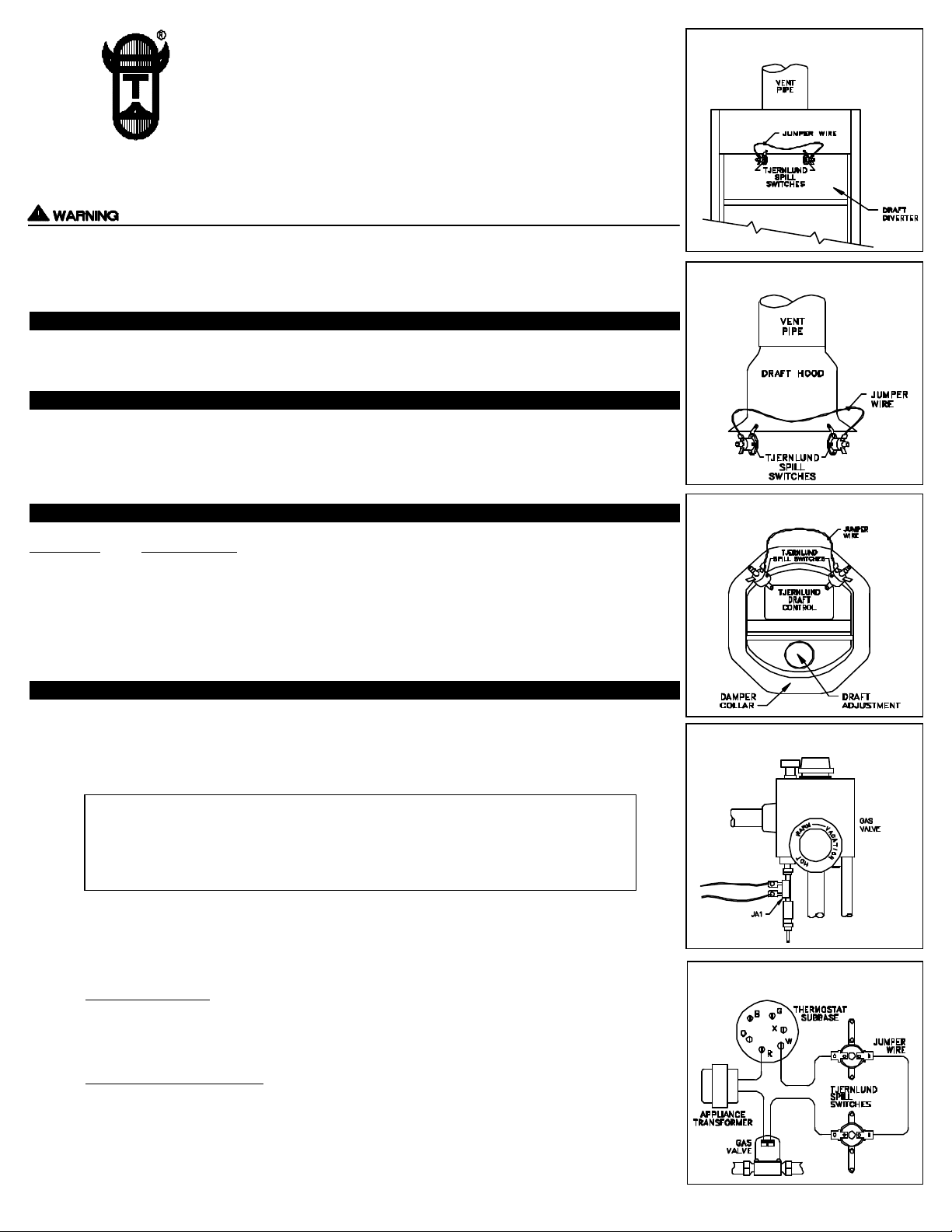
24SP200 SAFETY INTERLOCK SYSTEM(P/N 950-2420)
(For Millivolt and 24 Volt Control Systems only)
This Safety Interlock System may be used on conventional chimney or Power Vented appliances
equipped with a draft hood, draft diverter or draft control.
PURPOSE
To provide a means for appliance shut-down in the event of flue blockage or down drafts.
OPERATION
The Spill Switch circuits are “normally closed” and will not affect normal appliance operation. When concentrated spillage of combustion gases occurs from the draft hood, diverter or barometric control, the
Spill Switch circuit will open preventing burner operation.
DIAGRAM A1
DIAGRAM A2
PARTS LIST
QUANTITY DESCRIPTION
(2) Spill Switches with manual reset, 200oF set point
(1) Wire routing packet
(1) 8” jumper wire
(1) 6’ 16/2 jacketed cable
INSTALLATION
1. Shut off fuel supply to the appliance.
2. Attach Spill Switches to draft hood (A1), diverter (A2) or barometric control (A3), see respective
diagram.
IMPORTANT:
Sensing area on underside of Spillage Switch should not come in direct contact with
metal surfaces. Sensing Switches should be mounted so they will sample temperature
of gas spilling from vent or chimney, not temperature of metal surface.
3. Attach 8” jumper wire to inside terminals of draft spillage sensing switches.
DIAGRAM A3
DIAGRAM B1
Spill Switch
Cables
4. Attach leads of jacketed cable to outside terminals of spillage switches.
5a. WATER HEATERS:
Millivolt water heaters require the Tjernlund Model JA-1 (P/N 950-0470), Thermocouple
Junction Adapter (ordered separately). Connect ends of six foot cable to spade connections on
Thermocouple Adapter, (See Diagram B1).
5b. FURNACES AND BOILERS:
Splice ends of six foot cable in a series circuit between the thermostat and gas valve or burner
control, (See Diagram B2).
Using cable routing tabs from wire routing packet, attach 6’ cable to appliance maintaining a
safe distance from hot surfaces, e.g. appliance vent pipe and hot water pipes.
DIAGRAM B2
Page 2
SAFETY INTERLOCK TEST
REV. 1, 3/97
© 1997 TJERNLUND PRODUCTS, INC.
P/N 8504056
1. Turn on fuel supply to the appliance.
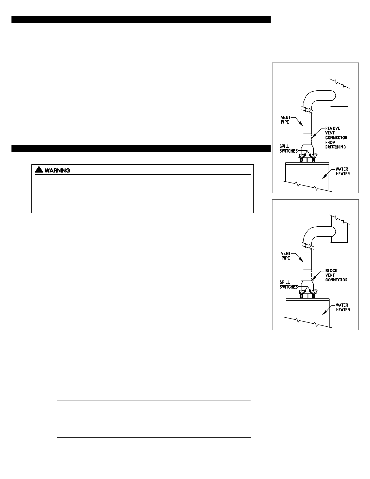
2. Remove vent connector from vent breaching at joint above Spillage Sensing Switches,
(See Diagram C1).
3. Block vent connector with sheet metal or other non-combustible material, (See Diagram C2).
4. Adjust thermostat to call for heat allowing burner to fire.
RESULT: Spillage will emit from draft hood, diverter or barometric control. In less than two min-
utes, Spillage Sensing Switches will open, preventing thermostat signal from reaching burner. If
Sensing Switches do not open, check for vent pipe leakage. Seal leaks and repeat steps 1-4.
5. Wait 2-3 Minutes...Push reset button on Spillage Sensing Switches.
6. Reconnect vent pipe to venting system. CAUTION: Metal vent pipe will be HOT!
COMBUSTION AIR TEST
The 24SP200 Flue Gas Spillage Sensing Kit is designed to alert the user to a potentially
hazardous condition. It is not designed to, and cannot replace regular chimney inspection,
appliance servicing and combustion testing. DO NOTUSE THE 24SP200 AS A SUBSTI-
TUTE FOR PROFESSIONAL APPLIANCE MAINTENANCE.
1. Close all doors and windows of the building. If appliance is installed in utility room or closet, close
the entrance door to this room. Close fireplace dampers.
DIAGRAM C1
DIAGRAM C2
2. Turn on clothes dryer. Turn on all exhaust fans, such as range hoods, bathroom exhausts and
whole house fans to maximum speeds. Do not operate a fan used strictly for summer exhausting.
3. Set thermostat for continuous operation on the appliance that the 24SP200 has been installed on.
4. Allow fans and appliance to operate for 5 minutes.
5. Tripping of the Spillage Sensing circuit during the 5 minute appliance operation indicates an
unsafe operating condition. Check appliances for venting malfunction and check for adequate
combustion air. Turn off fuel supply to appliance and DO NOT OPERATE UNTIL UNSAFE
VENTING CONDITION IS INVESTIGATED BY PROFESSIONAL CONTRACTOR OR UTILITY
SERVICE PERSONNEL.
6. Return all windows, doors and fans to their previous conditions of use.
NOTE:
For further assistance contact the Tjernlund Products, Inc. Customer Service Department
at 1-800-255-4208. 7:30 AM-4:30 PM CST.
OWNERS INSTRUCTIONS
THESE INSTRUCTIONS MUST REMAIN WITH EQUIPMENT
DO NOT DESTROY
 Loading...