

Page 1
©2004 TJERNLUND PRODUCTS, INC. ALL RIGHTS RESERVED P/N: 8505022
TJERNLUND PRODUCTS, INC.
1601 Ninth Street • White Bear Lake, MN 55110-6794
PHONE (800) 255-4208 • (651) 426-2993 • FAX (651) 426-9547
Visit our web site • www.tjernlund.com
Qty (1) gas pressure switch Qty (1) 1/8-NPT pipe plug
Qty (1) 1/8-NPT black pipe tee Qty (2) brass 1/8-NPT male x ¼" compression fitting (Only (1) included in 950-2080 kit)
Qty (2) #10 x ½" self-tapping screws Qty (1) section of ¼" outside diam. aluminum tubing (Not included in 950-2080 kit)
NEW STYLE GAS PRESSURE SWITCH INSTALLATION
The gas pressure switch is mounted on the casing of the water heater adjacent to the heater's thermostat/gas control valve. It
should be mounted close enough so that the supplied 1/4" tubing will reach from the gas pressure switch fitting to the thermostat/gas valve pressure tap port. The two provided screws are self-tapping and drilling. The screws do not require the use of a
drill and their 1/2" length assures that the inner tank will not be penetrated.
1. Mount the gas pressure switch by securing it to the heater casing with a screw in each of the two mounting holes.
IMPORTANT: Mount gas pressure switch so that diaphragm is in a VERTICAL
position, (See New Switch Diagram).
2. Install the supplied 1/8"-NPT pipe plug to the 90
o
port of the supplied 1/8-NPT black pipe tee, (See New Switch Diagram). Use
thread sealant, do not over tighten.
3. Install the 1/8-NPT black pipe tee to the gas pressure switch, (See New Switch Diagram). Use thread sealant, do not over
tighten. CAUTION: Utilize the hex nut on the gas pressure switch when attaching the black pipe tee.
4. Install the supplied Brass 1/8-NPT male x ¼" compression fitting to the 1/8-NPT black pipe tee, (See New Switch Diagram ).
Use thread sealant, do not over tighten.
5. Remove the PRESSURE TAP plug from the underside of the thermostat/gas control valve and install the supplied Brass
1/8-NPT male x ¼" compression fitting, (See New Switch Diagram). Use thread sealant, do not over tighten.
IMPORTANT: DO NOT alter the heater's PILOT GAS LINE, (See New Switch Diagram).
6. Using a tube cutter, cut the appropriate length of the supplied 1/4" tubing to reach from the gas pressure switch fitting to the
PRESSURE TAP PORT fitting of the thermostat/gas control valve. Make sure each end of the tubing is not pinched closed.
7. Use the 1/4" tubing to connect gas pressure switch fitting to the PRESSURE TAP PORT fitting on the thermostat/gas control valve.
8. Conduct a gas leakage test of all connections as outlined in the latest edition of NFPA 54, ANSI Z223.1, part 4. or local codes.
NOTE: A "gauge port" can be accessed by removing the 1/8-NPT pipe plug that is on the 1/8-NPT black pipe tee (attached to
the gas pressure switch).
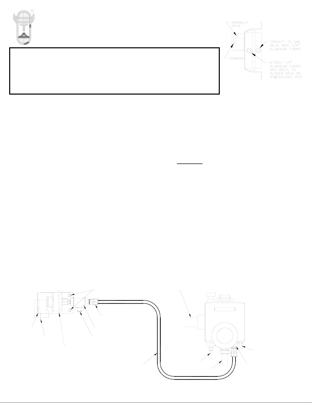
IMPORTANT: This gas pressure switch is an updated version with only one 1/4” aluminum
tubing connection to the pressure tap port of gas valve. The atmospheric vent connection
is no longer required, as on the Old-Style Switch. Disregard the “Gas Pressure Switch”
installation section of your VP-2/3, WHK-2, WHKE instruction manual if the old style switch
is referenced, (See Discontinued Old-Style Switch Diagram). If you are replacing an OldStyle gas pressure switch with the new style gas pressure switch follow the instructions
below. The new style switch is compatible with any previous Old-Style Switch installations.
Discontinued Old-Style Switch
DO NOT ALTER
GAS SUPPLY
INTO PRESSURE TAP PORT.
GAS PRESSURE SWITCH
GAS CONTROL VALVE
THERMOSTAT/
PILOT GAS LINE
FIGURE 700S107 2/13/04
INSTALL BRASS 1/8-NPT MALE
x 1/4" COMPRESSION FITTING
THERMOCOUPLE
BURNER GAS LINE
COMMON
MUST BE MOUNTED VERTICALLY.
GAS PRESSURE SWITCH DIAPHRAGM
IMPORTANT:
BRASS 1/8-NPT MALE x 1/4"
COMPRESSION FITTING
THERMOSTAT / GAS CONTROL
TO PRESSURE TAP FITTING OF
1/4" OUTSIDE DIAMETER
ALUMINUM TUBING - CONNECT
VALVE.
1/8-NPT BLACK PIPE TEE
1/8-NPT PIPE PLUG - NEW
PRESSURE TAP PORT
NORMALLY OPEN
MOUNTING HOLES
IMPORTANT:
New-Style Gas Pressure
Switch Installation
 Loading...