

Page 1
TJERNLUND PRODUCTS, INC.
1601 Ninth Street • White Bear Lake, MN 55110-6794
PHONE (651) 426-2993 • (800) 255-4208 • FAX (651) 426-9547
Visit our web site • www.tjernlund.com
(950-1040) 24VAC RELAY INSTALLATION INSTRUCTIONS
OWNERS INSTRUCTIONS
THESE INSTRUCTIONS MUST
REMAIN WITH EQUIPMENT
DO NOT DESTROY
ALWAYS FOLLOW HEATER MANU-
FACTURER’S INSTRUCTIONS FOR
PROPER OPERATION OF HEATER
AND RE-LIGHTING OF PILOT
READ INSTRUCTIONS CAREFULLY PRIOR TO INSTALLATION
1. The Tjernlund 24V Relay Part #950-1040 may be used as a replacement part or as an added accessory to Tjernlund
Draft Inducers, the MAC-3 controller & IN-FORCER combustion air intakes wired to 24V control circuits. Please refer
to section A of these instructions if installing it as a replacement part and section B if installing it as an accessory part.
2. Terminals 7 and 8 of the 24VAC Relay are rated for an input of 24VAC only! DO NOT APPLY 115VAC TO
TERMINALS 7 AND 8 OF THE RELAY.
Disconnect 115VAC power from the Power Venter before continuing. All wiring from the Power Venter to the appliance
must be appropriate class 1 wiring as follows: installed in rigid metal conduit, intermediate metal conduit, rigid non-metallic
conduit, electrical metallic tubing, Type MI Cable, Type MC Cable, or be otherwise suitably protected from physical damage.
SECTION A
1. Remove the electrical box cover plate of the Power Venter.
2. Place the replacement relay next to the defective relay located in the Power Venter electrical box.
3. One by one, remove the wires from the defective relay and connect them to the corresponding terminal on the
replacement relay.
4. Carefully drill the rivets out that are holding the defective relay to the junction box.
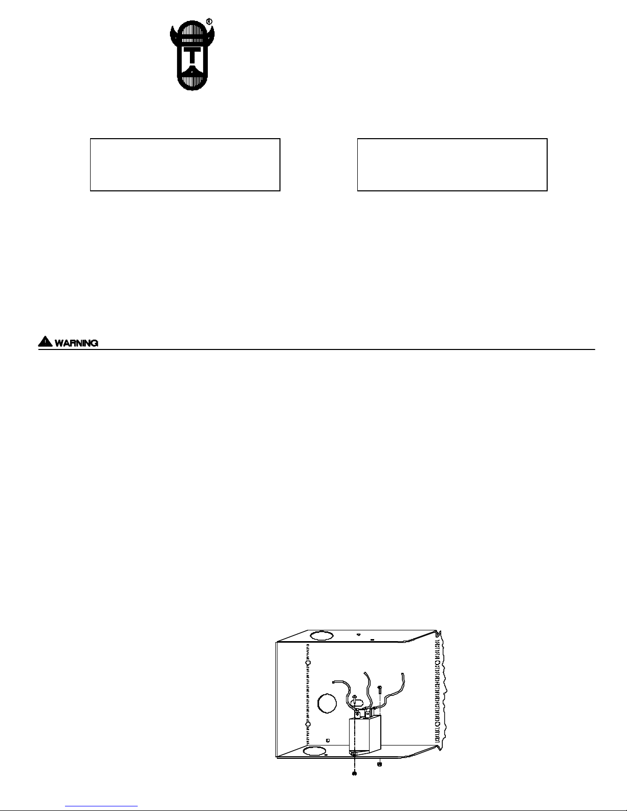
5. Install the replacement relay in the electrical box and secure it with the nuts/screws provided, (See Diagram A).
6. Reestablish power to the Power Venter and equipment. Run equipment through a couple of heating cycles to verify
proper operation.
7. If defective relay failed within the one year warranty period, you may return it along with proof of purchase to the
Tjernlund Distributor it was originally purchased from for a full refund.
SECTION B
1. Remove the electrical box cover from the Power Venter/Draft Inducer.
2. Secure the relay to the inside of the electrical box using the nut/screw provided, (See Diagram A).
3. Wire the relay according to the appropriate diagram on back of this page for your installation.
4. Run equipment through a couple of heating cycles to verify proper operation.
DIAGRAM A
P/N: 8504052 ©1997 TJERNLUND PRODUCTS, INC. ALL RIGHTS RESERVED REV. 3, 10/97
Page 2

TYPICAL 24V GAS ELECTRONIC IGNITION WIRING WITH POWER VENTER/DRAFT INDUCER
950-1040
RELAY
TYPICAL 24V GAS STANDING PILOT WIRING WITH POWER VENTER/DRAFT INDUCER
950-1040
RELAY
NOTE
IF YOUR ELECTRICAL DIAGRAM IS NOT INCLUDED, CONTACT OUR CUSTOMER SERVICE
DEPARTMENT AT 1-800-255-4208, 7:30 TO 4:30 CST FOR FURTHER ASSISTANCE.
 Loading...