

Page 1
GB
Operating manual
Betriebsanleitung ............p. 28
Mode d’emploi ................. p. 56
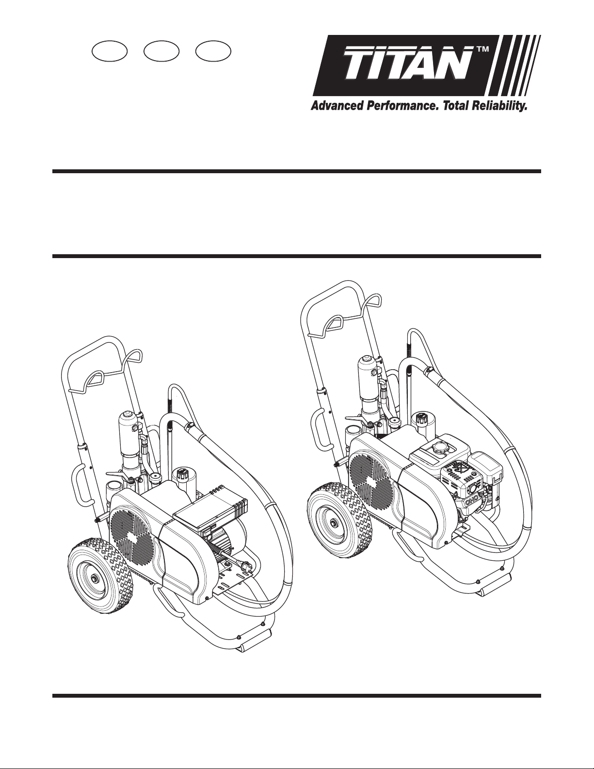
Airless high-pressure spraying unit
Airless Hochdruck-Spritzgerät
Groupe de projection à haute pression
D F
PowrTwin Plus
Model 0290012 (PT4900)
0290013 (PT6900)
0290018 (PT8900)
Model 0290032 (PT4900)
Edition 9 / 2016 0290 935L
Ausgabe
0290016 (PT12000)
Page 2
Original Operating Manual
Airless units develop extremely high spraying pressures.
Never put your ngers, hands or any other parts of the body into
the spray jet!
1
Never point the spray gun at yourself, other persons or animals.
Never use the spray gun without safety guard.
GB
Warning!
Attention: Danger of injury by injection!
2
3
Do not treat a spraying injury as a harmless cut. In case of injury
to the skin through coating materials or solvents, consult a doctor
immediately for quick and expert treatment. Inform the doctor
about the coating material or solvent used.
The operating instructions state that the following points must
always be observed before starting up:
1. Faulty units must not be used.
2. Secure Titan spray gun using the safety catch on the trigger.
3. Ensure that the unit is properly earthed.
4. Check allowable operating pressure of high-pressure hose and spray
gun.
5. Check all connections for leaks.
The instructions regarding regular cleaning and maintenance of
the unit must be strictly observed.
Before any work is done on the unit or for every break in work the
following rules must be observed:
1. Release the pressure from spray gun and hose.
2. Secure the Titan spray gun using the safety catch on the trigger.
3. Switch o unit.
Be safety conscious!
2 PowrTwin Plus
Page 3

GB
Contents
Contents
Page
1. Safety regulations for Airless spraying ...................................... 2
1.1 Explanation of symbols used .............................................................. 2
1.2 Electrical safety ......................................................................................... 3
1.3 Gasoline engine safety .......................................................................... 4
1.4 Fueling (gas engine) ............................................................................... 4
2. General view of application ............................................................. 5
2.1 Application ................................................................................................ 5
2.2 Coating materials .................................................................................... 5
3. Description of unit................................................................................ 5
3.1 Airless process .......................................................................................... 5
3.2 Functioning of the unit ......................................................................... 5
3.3 System diagram - gasoline PT units .................................................. 6
3.4 System diagram - electric PT units .................................................... 7
3.5 Technical data for PT units ................................................................... 8
3.6 Airless Spray Tip Recommendation Chart ...................................... 9
4. Operation ................................................................................................10
4.1 Setup .......................................................................................................... 10
4.2 Preparing a new sprayer ..................................................................... 11
4.3 Preparing to paint ................................................................................. 12
4.4 Painting ..................................................................................................... 13
4.5 Pressure relief procedure ...................................................................13
5. Cleanup .................................................................................................... 14
5.1 Special cleanup instructions for use with
ammable solvents ..............................................................................14
5.2 Cleaning the sprayer ............................................................................ 14
5.3 Cleaning a clogged tip ........................................................................ 14
Page
7. Troubleshooting .................................................................................25
7.1 Airless gun ...............................................................................................25
7.2 Fluid section ............................................................................................ 25
7.3 Hydraulic motors ................................................................................... 26
7.4 Spray patterns ........................................................................................27
Accessories and spare parts ........................................................................84
Spare parts list for the main assembly .................................................. 84/85
Spare parts list for the cart assembly .................................................... 86/87
Spare parts list for the hydraulic system .............................................. 88/89
Spare parts list for the hydraulic motor ............................................... 90/91
Spare parts list for the uid section • PT4900 ..................................... 92/93
Spare parts list for the uid section •
PT6900 / PT8900 / PT12000 ...................................................................... 94/95
Spare parts list for gas convertokit ........................................................ 96/97
Spare parts list for electric convertokit (230V) ................................... 98/99
Spare parts list for the high-pressure lter ..............................................100
Spare parts list for belt guard assembly ....................................................101
Spare parts list for bleed hose assembly with valve .............................102
Spare parts list for bleed valve .....................................................................103
Spare parts list fo siphon hose assembly ..................................................104
Connection diagram (230V) .......................................................................105
Accessories for PT units ...............................................................................106
Gun manifold assemblies (optional) ..........................................................108
Warranty .............................................................................................................109
6. Maintenance..........................................................................................15
6.1 Daily maintenance ................................................................................ 15
6.2 Maintaining the lter assembly........................................................15
6.3 Maintaining the hydraulic system ................................................... 17
6.4 Maintaining the uid section ............................................................ 17
6.5 Basic engine maintenance ................................................................. 17
6.6 Replacing the motor brushes (120V electric convertokit) ...... 18
6.7 Replacing the belt ................................................................................. 19
6.8 Servicing the hydraulic motor .......................................................... 20
6.9 Servicing the uid section .................................................................. 22
6.10 SAE O-ring tting installation ...........................................................24
PowrTwin Plus 1
Page 4
Safety precautions
At
i
1. Safety regulations for Airless spraying
1.1 Explanation of symbols used
This manual contains information that must be read and understood
before using the equipment. When you come to an area that has one
of the following symbols, pay particular attention and make certain
to heed the safeguard.
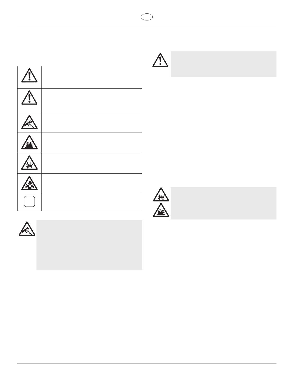
This symbol indicates a potential hazard that
may cause serious injury or loss of life. Important
safety information will follow.
This symbol indicates a potential hazard to you
or to the equipment. Important information that
tention
tells how to prevent damage to the equipment or
how to avoid causes of minor injuries will follow.
Danger of skin injection
Danger of fire from solvent and paint fumes
Danger of explosion from solvent, paint fumes
and incompatible materials
Danger of injury from inhalation of harmful
vapors
GB
• All accessories must be rated at or above the maximum
operating pressure range of the sprayer. This includes spray
tips, guns, extensions, and hose.
HAZARD
The paint hose can develop leaks from wear, kinking
and abuse. A leak can inject material into the skin.
Inspect the hose before each use.
PREVENTION:
• Avoid sharp bending or kinking of the high-pressure hose. The
smallest bending radius amounts to about 20 cm.
• Do not drive over the high-pressure hose. Protect against
sharp objects and edges.
• Replace any damaged high-pressure hose immediately.
• Never repair defective high-pressure hoses yourself!
• Electrostatic charging of spray guns and the high-pressure
hose is discharged through the high-pressure hose. For this
reason the electric resistance between the connections of the
high-pressure hose must be equal to or lower than 1M.
• For reasons of function, safety and durability use only original
Titan high-pressure hoses.
• Before each use, check all hoses for cuts, leaks, abrasion
or bulging of cover. Check for damage or movement of
couplings. Immediately replace the hose if any of these
conditions exist. Never repair a paint hose. Replace it with
another earthed high-pressure hose.
• Make sure power cord, air hose and spray hoses are routed in
such a manner to minimize slip, trip and fall hazard.
: HIGH PRESSURE HOSE
Notes give important information which should
be given special attention.
HAZARD: INJECTION INJURY
A high pressure stream produced by this equipment
can pierce the skin and underlying tissues, leading to
serious injury and possible amputation.
Do not treat a spraying injury as a harmless cut. In
case of injury to the skin through coating materials
or solvents, consult a doctor immediately for quick
and expert treatment. Inform the doctor about the
coating material or solvent used.
PREVENTION:
• NEVER aim the gun at any part of the body.
• NEVER allow any part of the body to touch the uid stream.
DO NOT allow body to touch a leak in the uid hose.
• NEVER put your hand in front of the gun. Gloves will not
provide protection against an injection injury.
• ALWAYS lock the gun trigger, shut the uid pump o and
release all pressure before servicing, cleaning the tip guard,
changing tips, or leaving unattended. Pressure will not be
released by turning o the engine. The PRIME/SPRAY valve
or pressure bleed valve must be turned to their appropriate
positions to relieve system pressure.
• ALWAYS keep tip guard in place while spraying. The tip guard
provides some protection but is mainly a warning device.
• ALWAYS remove the spray tip before ushing or cleaning the
system.
• NEVER use a spray gun without a working trigger lock and
trigger guard in place.
HAZARD: EXPLOSION OR FIRE
Flammable vapors, such as solvent and paint vapors,
in work area can ignite or explode.
PREVENTION:
• Use equipment only in well ventilated area. Keep a good
supply of fresh air moving through the area to keep the air
within the spray area free from accumulation of ammable
vapors. Keep pump assembly in well ventilated area. Do not
spray pump assembly.
• Electric models only - Do not use materials with a ashpoint
below 38º C (100º F). Flashpoint is the temperature at which a
uid can produce enough vapors to ignite.
• Gas models only - Do not ll fuel tank while engine is running
or hot; shut o engine and allow to cool. Fuel is ammable
and can ignite or explode if spilled on a hot surface.
• Eliminate all ignition sources, such as pilot lights, cigarettes,
portable electric lamps and plastic drop cloths (potential static
arc).
• Keep work area free of debris, including solvent, rags and
gasoline.
• Do not plug or unplug power cords, or turn power or light
switches on or o when ammable vapors are present.
• Ground equipment and conductive objects in work area.
Make sure the grounding cable (not equipped) is connected
from the grounding lug to a true earth ground.
• Use only grounded hoses.
• Hold spray gun rmly to the side of a grounded pail when
triggering into pail.
• If there is static sparking or if you feel a shock, stop operation
immediately.
2 PowrTwin Plus
Page 5
GB
Safety precautions
• Know the contents of the paint and solvents being sprayed.
Read all Material Safety Data Sheets (MSDS) and container
labels provided with the paints and solvents. Follow the paint
and solvent manufacturer’s safety instructions.
• Do not use a paint or solvent containing halogenated
hydrocarbons. Such as chlorine, bleach, mildewcide,
methylene chloride and trichloroethane. They are not
compatible with aluminum. Contact the coating supplier
about compatibility of material with aluminum.
• Keep a re extinguisher in work area.
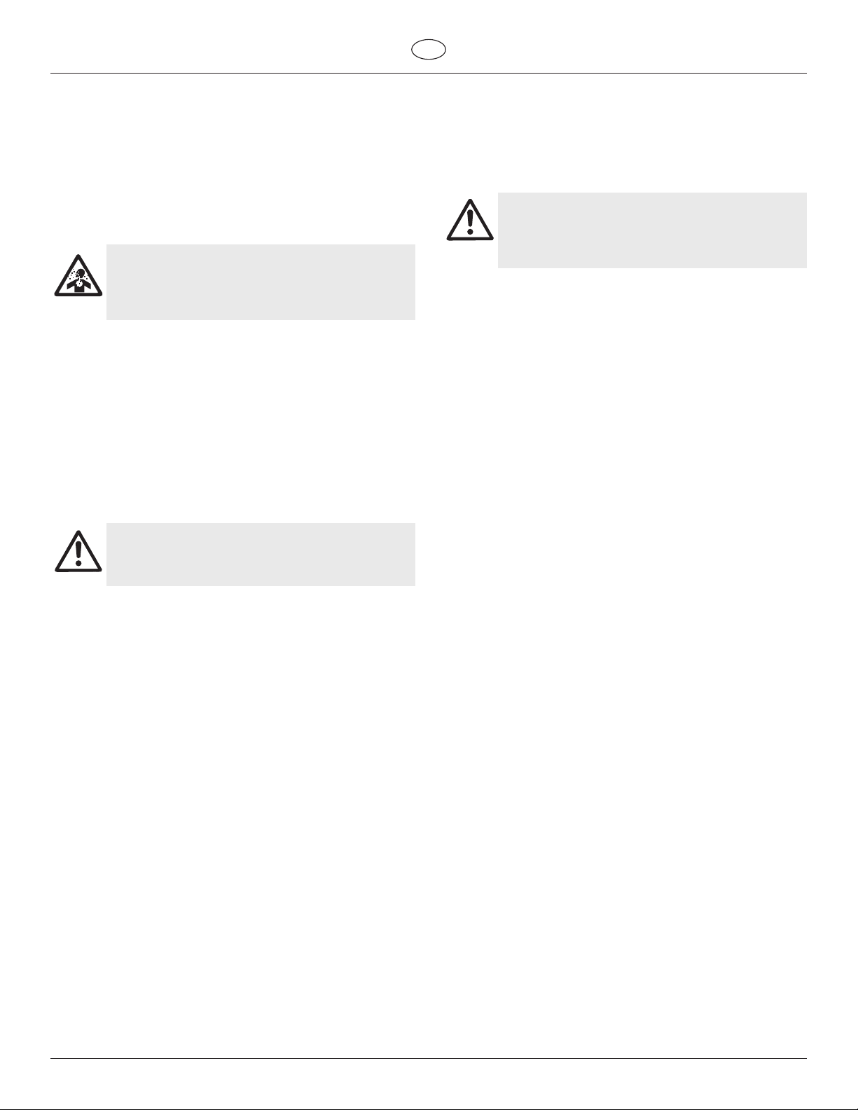
HAZARD: HAZARDOUS VAPORS
Paints, solvents, and other materials can be harmful
if inhaled or come in contact with body. Vapors can
cause severe nausea, fainting, or poisoning.
1.2 Electric Safety
Electric models must be earthed. In the event of an electrical short
circuit, earthing reduces the risk of electric shock by providing an
escape wire for the electric current. This product is equipped with
a cord having an earthing wire with an appropriate earthing plug.
Connection to the mains only through a special feed point, e.g.
through an error protection insallation with INF < 30 mA.
DANGER — Work or repairs at the electrical
equipment may only be carried out by a skilled
electrician. No liability is assumed for incorrect
installation. Switch the unit o. Before all repair
work, unplug the power plug from the outlet.
Danger of short-circuits caused by water ingressing into the electrical
equipment. Never spray down the unit with high-pressure or high-
pressure steam cleaners.
PREVENTION:
• Wear respiratory protection when spraying. Read all
instructions supplied with the mask to be sure it will provide
the necessary protection.
• All local regulations regarding protection against hazardous
vapors must be observed.
• Wear protective eyewear.
• Protective clothing, gloves and possibly skin protection cream
are necessary for the protection of the skin. Observe the
regulations of the manufacturer concerning coating materials,
solvents and cleaning agents in preparation, processing and
cleaning units.
HAZARD: GENERAL
This product can cause severe injury or property
damage.
PREVENTION:
• Follow all appropriate local, state, and national codes
governing ventilation, re prevention, and operation.
• Pulling the trigger causes a recoil force to the hand that is
holding the spray gun. The recoil force of the spray gun is
particularly powerful when the tip has been removed and
a high pressure has been set on the airless pump. When
cleaning without a spray tip, set the pressure control knob to
the lowest pressure.
• Use only manufacturer authorized parts. User assumes all
risks and liabilities when using parts that do not meet the
minimum specications and safety devices of the pump
manufacturer.
• ALWAYS follow the material manufacturer’s instructions for
safe handling of paint and solvents.
• Clean up all material and solvent spills immediately to prevent
slip hazard.
• Wear ear protection. This unit can produce noise levels above
85 dB(A).
• Never leave this equipment unattended. Keep away from
children or anyone not familiar with the operation of airless
equipment.
• Do not spray on windy days.
• The device and all related liquids (i.e. hydraulic oil) must be
disposed of in an environmentally friendly way.
Work or repairs at the electrical equipment:
These may only be carried out by a skilled electrician. No liability is
assumed for incorrect installation.
Operating Temperature
This equipment will operate correctly in its intended ambient, at a
minimum between +10°C and +40°C.
Relative Humidity
The equipment will operate correctly within an environment at 50%
RH, +40°C. Higher RH may be allowed at lower temperatures.
Measures shall be taken by the Purchaser to avoid the harmful eects
of occasional condensation.
Altitude
This equipment will operate correctly up to 2100 m above mean sea
level.
Transportation and Storage
This equipment will withstand, or has been protected against,
transportation and storage temperatures of -25°C to +55°C and for
short periods up to +70°C.
It has been packaged to prevent damage from the eects of normal
humidity, vibration and shock.
PowrTwin Plus 3
Page 6
Safety precautions
Attention
GB
1.3 Gasoline Engine Safety
1. Gas engines are designed to give safe and dependable service
if operated according to instructions. Read and understand
the engine manufacturer’s Owner’s Manual before operating
the engine. Failure to do so could result in personal injury or
equipment damage.
2. To prevent re hazards and to provide adequate ventilation,
keep the engine at least 1 meter (3 feet) away from buildings
and other equipment during operation. Do not place
ammable objects close to the engine.
3. People who are not operating the device must stay away from
the area of operation due to a possibility of burns from hot
engine components or injury from any equipment the engine
may be used to operate.
4. Know how to stop the engine quickly, and understand the
operation of all controls. Never permit anyone to operate the
engine without proper instructions.
5. Gasoline is extremely ammable and is explosive under
certain conditions.
6. Refuel in a well-ventilated area with the engine stopped. Do
not smoke or allow ames or sparks in the refueling area or
where gasoline is stored.
7. Do not overll the fuel tank. After refueling, make sure the
tank cap is closed properly and securely.
8. Be careful not to spill fuel when refueling. Fuel vapor or
spilled fuel may ignite. If any fuel is spilled, make sure the area
is dry before starting the engine.
9. Never run the engine in an enclosed or conned area. Exhaust
contains poisonous carbon monoxide gas; exposure may
cause loss of consciousness and may lead to death.
10. The muer becomes very hot during operation and remains
hot for a while after stopping the engine. Be careful not to
touch the muer while it is hot. To avoid severe burns or re
hazards, let the engine cool before transporting it or storing it
indoors.
11. Never ship/transport sprayer with gasoline in the tank.
1.4 Fueling (gas engine)
Gasoline is extremely flammable and is explosive
under certain conditions.
Do not overll the gas tank. Overlling can cause
the gas cap to become clogged with any particles
in the gasoline which can cause a vaccum. Read
Attention
Fuel Specications
• Use automotive gasoline that has a pump octane number of
i
• Unleaded fuel produces fewer engine and spark plug deposits
• Never use stale or contaminated gasoline or an oil/gasoline
the gas engine’s instruction manual for fueling
instructions.
86 or higher, or that has a research octane number of 91 or
higher. Use of a lower octane gasoline can cause persistent
“pinging” or heavy “spark knock” (a metallic rapping noise)
which, if severe, can lead to engine damage.
If “spark knock” or “pinging” occurs at a steady
engine speed under normal load, change brands of
gasoline. If spark knock or pinging persists, consult
an authorized dealer of the engine manufacturer.
Failure to do so is considered misuse, and damage
caused by misuse is not covered by the engine
manufacturer’s limited warranty.
Occasionally you may experience light spark knock
while operating under heavy loads. This is no
cause for concern, it simply means your engine is
operating eciently.
and extends the life of the exhaust system components.
mixture. Avoid getting dirt, dust, or water in the fuel tank.
DO NOT use this equipment to spray water or acid.
Do not lift by cart handle when loading or unloading.
Device is very heavy. Three-person lift is required.
Gasolines Containing Alcohol
If you decide to use a gasoline containing alcohol (gasohol), be
sure its octane rating is at least as high as that recommended by
the engine manufacturer. There are two types of “gasohol”: one
containing ethanol, and the other containing methanol. Do not use
gasohol that contains more than 10% ethanol. Do not use gasoline
containing methanol (methyl or wood alcohol) that does not also
contain co-solvents and corrosion inhibitors for methanol. Never
use gasoline containing more than 5% methanol, even if it has cosolvents and corrosion inhibitors.
Fuel system damage or engine performance
i
problems resulting from the use of fuels that contain
alcohol is not covered under the warranty. The
engine manufacturer cannot endorse the use of
fuels containing methanol since evidence of their
suitability is incomplete at this time.
Before buying gasoline from an unfamiliar station, try
to nd out if the gasoline contains alcohol. If it does,
conrm the type and percentage of alcohol used. If
you notice any undesirable operating characteristics
while using a gasoline that contains alcohol, or one
that you think contains alcohol, switch to a gasoline
that you know does not contain alcohol.
4 PowrTwin Plus
Page 7
GB
i
General view of application Description of unit
2. General view of application
2.1 Application
Priming and nal coating of large areas, sealing, impregnation,
construction sanitation, façade protection and renovation, rust
protection and building protection, roof coating, roof sealing,
concrete sanitation, as well as heavy corrosion protection.
Examples of objects to be sprayed
Large-scale construction sites, underground construction, cooling
towers, bridges, sewage treatment plants and terraces.
2.2 Coating materials
Processible coating materials
Pay attention to the Airless quality of the coating
materials to be processed.
Latex paint, dispersion paints, re protection and thick lm materials,
zinc dust and micaceous iron ore paints, Airless spray primer,
sprayable glue, anti-corrosive agents, thick coating materials and
bitumen-like coating materials.
No other materials should be used for spraying without Titan’s
approval.
Filtering
In spite of the high-pressure lter, ltering of the coating material is
to be recommended in general (except when processing airless joint
ller).
Stir coating material before commencement of work.
Make sure when stirring with motor-driven agitators
i
that no air bubbles are stirred in. Air bubbles disturb
when spraying and can, in fact, lead to interruption
of operation.
3. Description of unit
3.1 Airless process
The main area of application are thick layers of highly viscous coating
material for large areas and a high consumption of material.
A piston pump takes in the coating material by suction and conveys it
to the tip. Pressed through the tip at a pressure of up to a maximum
of 3300-3600 PSI (228-248 bar, 24.4-24.8 MPa), the coating material is
atomised. This high pressure has the eect of micro ne atomisation
of the coating material.
As no air is used in this process, it is described as an AIRLESS process.
This method of spraying has the advantages of nest atomisation,
cloudless operation and a smooth, bubble-free surface. As well as
these, the advantages of the speed of work and convenience must be
mentioned.
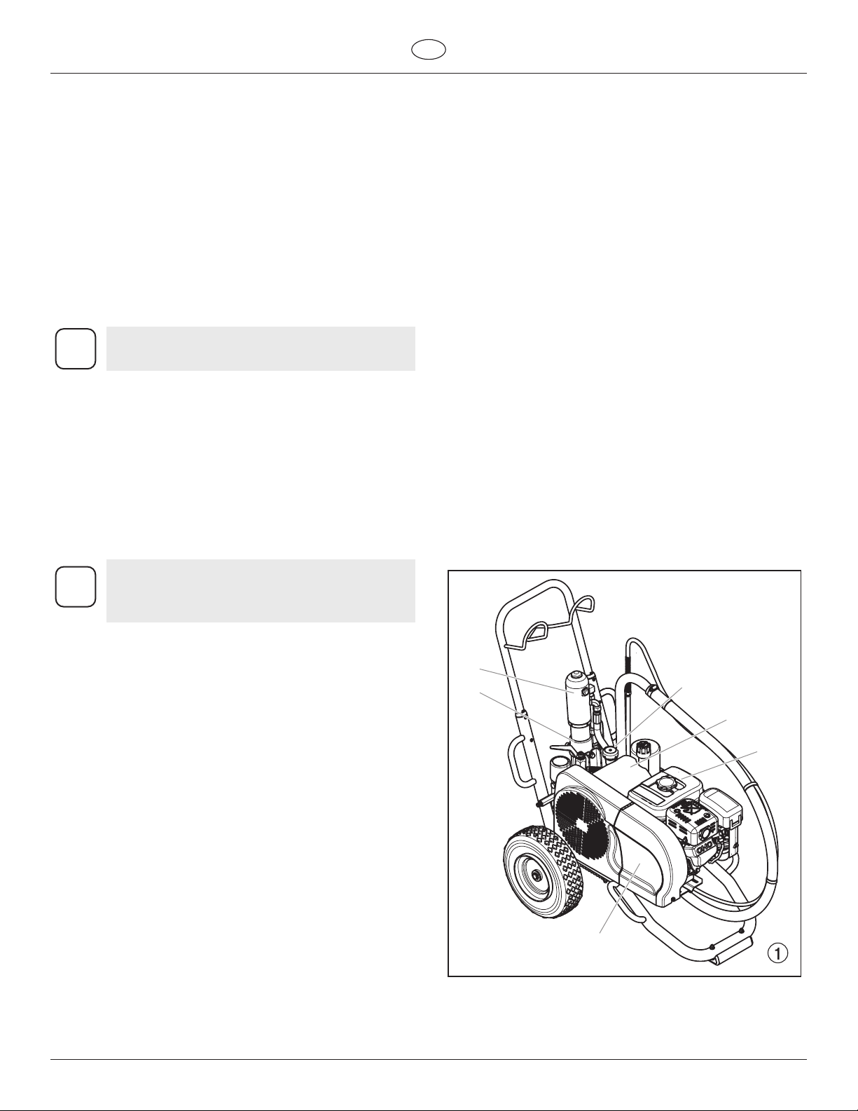
3.2 Functioning of the unit
The following section contains a brief description of the technical
construction for better understanding of the function.
TITAN PowrTwin Plus (PT) are high-pressure spraying units driven by
either a gasoline engine or electric motor.
The gasoline engine or electric motor (g. 1, item 1) drives the
hydraulic pump (3) by means of a V-belt which is under the belt cover
(2). Hydraulic oil ows to the hydraulic motor (4) and then moves the
piston up and down in the material feed pump (5).
The inlet valve is opened automatically by the upwards movement
of the piston. The outlet valve is opened when the piston moves
downward.
The coating material ows under high pressure through the highpressure hose to the spray gun. When the coating material exits from
the tip it atomises.
The pressure control valve (6) controls the volume and the operating
pressure of the coating material.
Viscosity
It is possible to work with high-viscosity coating materials with the
devices.
If highly viscous coating materials cannot be sucked up, they must be
diluted in accordance with the manufacturer’s instruction.
Two-component coating material
The appropriate processing time must be adhered to exactly. Within
this time rinse through and clean the unit meticulously with the
appropriate cleaning agents.
Coating materials with sharp-edged additional materials
These have a strong wear and tear eect on valves, high-pressure
hose, spray gun and tip. The durability of these parts can be reduced
appreciably through this.
4
5
6
3
1
2
PowrTwin Plus 5
Page 8
Description of unit
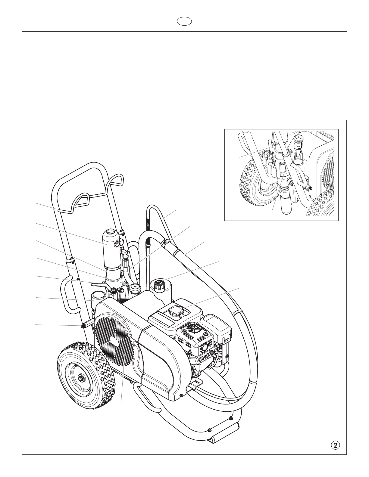
3.3 System diagram - gasoline PT units
GB
1 Extractable handle
2 Hydraulic motor
3 Oil cup for separating oil (separating oil prevents increased
wear and tear of the packings)
4 Pressure control knob
5 Relief valve handle: Turn left for circulation k
Turn right for spray p
6 High-pressure lter
1
2
7 High-pressure hose outlet
8 V-belt under the belt cover
9 Bleed hose
10 Ball valve: horizontal position – hydraulic motor switched o
vertical position – hydraulic motor switched on
11 Suction tube
12 Oil measuring stick
13 Gasoline engine
10
9
3
10
3
4
11
12
5
13
6
7
8
6 PowrTwin Plus
Page 9
GB
Description of unit
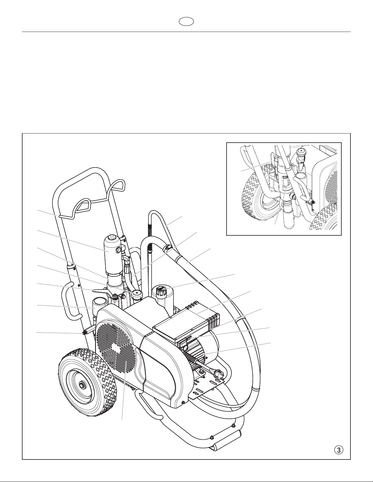
3.4 System diagram - electric PT units
1 Extractable handle
2 Hydraulic motor
3 Oil cup for separating oil (separating oil prevents increased
wear and tear of the packings)
4 Pressure control knob
5 Relief valve handle: Turn left for circulation k
Turn right for spray p
6 High-pressure lter
7 High-pressure hose outlet
8 V-belt under the belt cover
1
2
9 Bleed hose
10 Ball valve: horizontal position – hydraulic motor switched o
vertical position – hydraulic motor switched on
11 Suction tube
12 Oil measuring stick
13 Electric motor (230V)
14 ON/OFF switch
15 Control lamp that shows unit operational
16 Power Cord
10
9
10
3
3
11
4
12
5
13
6
14
15
7
16
8
PowrTwin Plus 7
Page 10

Description of unit
3.5 Technical data for PT units
GB
PT4900 Plus
(230V)
Gasoline engine, power
Subaru -------- 169cc, 5.7 Hp -------- -------- ------- Honda -------- -------- 163cc, 4.8 Hp 196cc, 5.5 Hp 270cc, 8.5 Hp
Fuel Capacity
-------- 0.95 US gal (3.6 l) 0.83 US gal (3.1 l) 0.83 US gal (3.1 l) 1.6 US gal (6.06 l)
Voltage
230 V~, 50 Hz -------- -------- -------- --------
Capacity
2.6 kW -------- -------- -------- --------
Power Cord
3 x 2.5 mm – 6 m -------- -------- -------- --------
Fuse Protection
16 A -------- -------- -------- --------
Max. operating pressure
Max. sound pressure level
80 dB (A)* 92 dB (A)* 98 dB (A)*
Max. size of tip with a spray gun
1-gun 0.031” – 0.79 mm 0.037” – 0.94 mm 0.050” – 1.27 mm 0.054” – 1.37 mm 0.059” – 1.50 mm
2-gun 0.028” – 0.71 mm 0.028” – 0.71 mm 0.033” – 0.84 mm 0.038” – 0.96 mm 0.040” – 1.01 mm
3-gun 0.022” – 0.56 mm 0.022” – 0.56 mm 0.023” – 0.58 mm 0.032” – 0.81 mm 0.034” – 0.86 mm
4-gun -------- -------- 0.019” – 0.48 mm 0.028” – 0.71 mm 0.030” – 0.76 mm
5-gun -------- -------- -------- 0.024” – 0.61 mm 0.026” – 0.66 mm
6-gun -------- -------- -------- -------- 0.024” – 0.61 mm
Max. volume ow
1.1 gal (4.2 l)/min 1.5 gal (5.7 l)/min 2.35 gal (8.9 l)/min 2.5 gal (9.5 l)/min 3.15 gal (11.9 l)/min
Weight
139 lbs. (63 kg) 132 lbs. (60 kg) 139 lbs. (63 kg) 154 lbs. (70 kg) 183 lbs. (83 kg)
Max. viscosity
Dimensions L x W x H
37.2” x 26.8” x 35” (946 x 680 x 890 mm)
Max. temperature of the coating material
Filter insert (standard equipment)
Hydraulic oil lling quantity
Max. tire pressure
Special high-pressure hose
PT4900 Plus
(gas)
22.8 MPa (228 bar, 3300 PSI) 24.8 MPa (248 bar, 3600 PSI)
50.000 mPa·s 65.000 mPa·s
DN 6 mm, 15 m (50’ x 1/4”), connection thread NPSM 1/4
PT6900 Plus PT8900 Plus PT12000 Plus
42.5” x 27” x 31” (1080
109ºF (43° C)
50 mesh, 18 in
5.9 l (1.56 gal) CoolFlo
0.2 MPa (2 bar, 30 PSI)
2
x 686 x 866 mm)
46” x 27” x 31” (1168 x 686 x
866 mm)
* Place of measurement: 1 m distance from unit and 1.60 m above reverberant oor, 120 bar (12 MPa) operating pressure.
8 PowrTwin Plus
Page 11

GB
Description of unit
3.6 Airless Spray Tip Recommendation Chart
Viscosity Filter Mesh Coating Orice Range Synergy™ (Fine Finish)
Light 100-150 Varnishes .009 - .011 .008 - .010
Lacquer Finishes (clear) .009 - .011 .008 - .010
Sanding Sealers .009 - .011 .008 - .010
Shellac (clear) .009 - .013 .008 - .012
Transparent Stain .011 - .013 .010 - .012
Water Sealers (clear) .011 - .013 .010 - .012
Medium 60-100 Solid Stains .013 - .015
Exterior House Paints .013 - .017
Interior Wall Paints .013 - .017
Interior & Exterior Primers .017 - .019
Heavy 30-60 Commercial Grade
Architectural Coatings .017 - .019
Interior Wall Paints .017 - .019
Interior Wall Primers .017 - .019
Dry Fall (quick dry) .019 - .023
One Coat, Primer-Finish Paints .019 - .023
Extra Heavy 0 Elastomerics .021 - .031
Pigmented Waterproofers .021 - .027
Block Filler .025 - .031
Orice sizes recommended on this chart are based on fan widths between 8 inches (20 cm) and 12 inches (30 cm)
PowrTwin Plus 9
Page 12
Operation
Attention
GB
4. Operation
This equipment produces a fluid stream at extremely
high pressure. Read and understand the warnings
in the Safety Precautions section at the front of this
manual before operating this equipment.
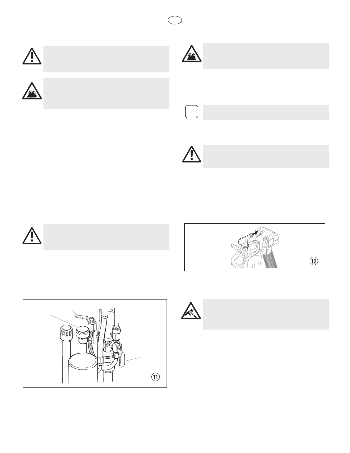
4.1 Setup
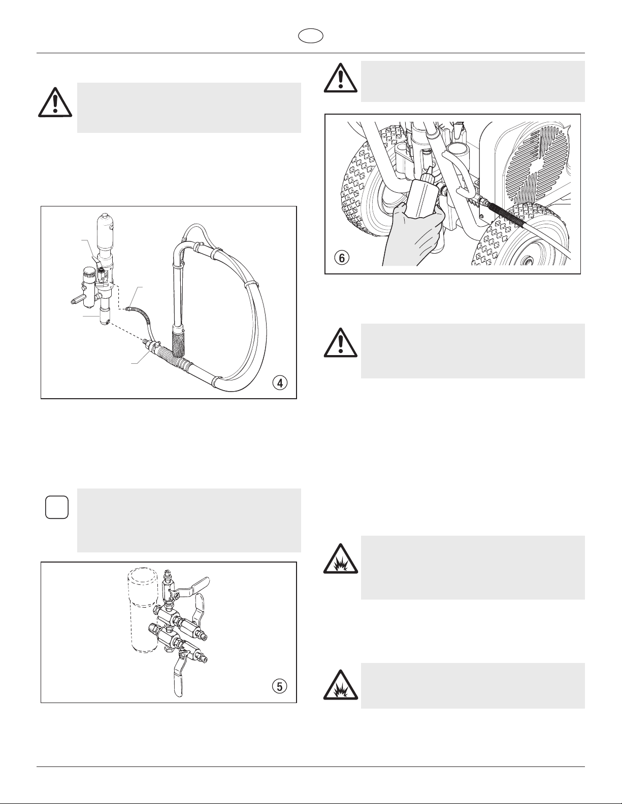
1. Make sure the siphon hose (g. 4, 1) is connected to the uid
section (2) and the bleed hose (3) is connected to the bleed
valve (4). They each have factory installed PTFE tape on the
male end of the hoses and should be wrench tight.
4
3
2
1
Piston Lube prevents increased wear and tear to the
packings.
5. Check the hydraulic uid level daily before starting the
sprayer. The hydraulic uid level should be at the “Full” mark
on the dipstick. Refer to the Maintenance section of this
manual for hydraulic system maintenance instructions.
Use of Titan’s Coolflo™ Hydraulic Fluid (P/N 430-361)
is mandatory in the hydraulic system. Do not use
any other hydraulic fluid. Use of any other hydraulic
Attention
fluid may seriously damage the hydraulic system
and will void the warranty.
2. Attach a minimum of 15m of nylon airless spray hose to the
sprayer. Do not use PTFE tape or thread sealant on the spray
hose connection.
3. Attach an airless spray gun to the spray hose. Do not attach
the tip to the spray gun yet. Remove the tip if it is already
attached.
a. To use two guns, remove the plug from the second gun outlet
4. Fill the oil cup 1/2 full with Piston Lube (P/N 314-480). This
on the lter assembly. Connect a hose and gun to the outlet.
For multiple gun operation, connect a multiple gun
i
manifold to the single gun outlet. Connect a hose
and gun to each outlet. Make sure the second gun
outlet remains plugged. See “Technical Data”,
Section 3.5 to determine number of guns and
maximum spray tip sizes.
extends packing life.
6. For gas models, check the engine oil level daily before starting
the sprayer. The gasoline engine oil level is determined by
the engine manufacturer. Refer to the engine manufacturer’s
service manual supplied with this sprayer.
7. For electric models, use a 20 amp service outlet. Always
locate the electric model within 10 to 15 feet of the service
outlet. Use a short electric cable and a long paint hose. Any
extension cord will create some voltage drop. If an extension
cord is necessary, use only a grounded 3-wire #12 extension
cord.
8. Make sure the sprayer is earthed. All sprayers are equipped
with a earthing lug. An earthing cable (not supplied) should
be used to connect the sprayer to a true earth ground.
Check your local electrical regulations for detailed earthing
instructions.
Proper earthing is important. This applies to both
gas and electric powered models. The passage of
some materials through the nylon uid hose will
build up a static electric charge, which if discharged,
could ignite solvent vapors present and create an
explosion.
9. Strain all paints with a nylon strainer to ensure trouble free
operation and freedom from frequent cleaning of the inlet
screen and gun lter.
10. Make sure the spray area is well ventilated to prevent
hazardous operation with volatile solvents or exhaust fumes.
If lacquer or other flammable materials are to be
sprayed, ALWAYS locate the sprayer outside the
immediate spraying area. Failure to do so may cause
an explosion.
11. Locate the sprayer outside the immediate spraying area to
avoid clogged air intake of the engine or electric motor with
overspray.
10 PowrTwin Plus
Page 13
GB
Operation
4.2 Preparing a New Sprayer
If this unit is new, it is shipped with test uid in the uid section to
prevent corrosion during shipment and storage. This uid must be
thoroughly cleaned out of the system with mineral spirits before you
begin spraying.
Always keep the trigger lock on the spray gun in the
locked position while preparing the system.
Attention
1. Place the siphon tube into a container of mineral spirits.
2. Place the bleed hose into a metal waste container.
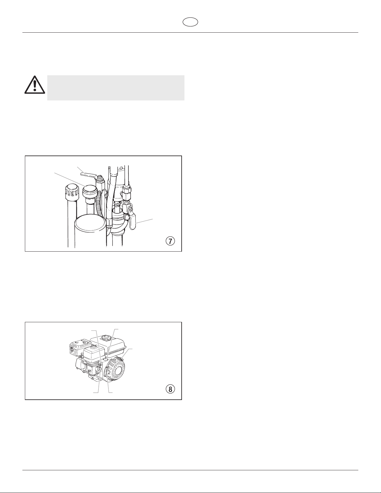
3. Turn the pressure control knob fully counterclockwise to its
lowest pressure setting (g 7, 1).
4. Open the hydraulic shut-o valve (2) located on the hydraulic
pressure hose. The handle should be in line with the hose.
5. Open the bleed valve (3) by turning it fully counterclockwise.
9. Turn o the sprayer.
a. To turn o the gas engine,
• set the pressure to minimum by turning the pressure control
knob fully counterclockwise,
• move the throttle lever to the slow position, and
• turn the engine switch to the OFF position.
b. To turn o the electric motor,
• set the pressure to minimum by turning the pressure control
knob fully counterclockwise,
• move the ON/OFF switch to the OFF position.
3
1
2
6. Start the engine or turn on the electric motor.
a. To start the gas engine (g. 8),
• move the fuel valve lever (2) to the open position,
• move the throttle lever (3) to its middle point,
• move the choke lever (4) to the closed position for a cold
• turn the engine switch (1) to the ON position, and
• pull the starter rope (5) briskly until the engine starts.
b. To start the electric motor, move the ON/OFF switch to the ON
engine or to the open position for a warm engine,
position.
4
3
1
2
5
7. Turn the pressure control knob (g. 7, 1) clockwise
approximately 1/3 of the way down to increase pressure until
the sprayer cycles evenly and solvent ows freely from the
bleed hose.
8. Allow the sprayer to run for 15–30 seconds to ush the test
uid out through the bleed hose and into the waste container.
PowrTwin Plus 11
Page 14
i
Operation
GB
4.3 Preparing to Paint
Before painting, it is important to make sure that the uid in the
system is compatible with the paint that is going to be used.
Incompatible uids and paint may cause the valves
i
Attention
1. Place the siphon tube into a container of the appropriate
i
2. Place the bleed hose into a metal waste container.
3. Turn the pressure control knob fully counterclockwise to its
4. Open the hydraulic shut-o valve (2) located on the hydraulic
5. Open the bleed valve (3) by turning it fully counterclockwise.
6. Start the engine or turn on the electric motor.
a. To start the gas engine (g. 8),
• move the fuel valve lever (2) to the open position,
• move the throttle lever (3) to its middle point,
• move the choke lever (4) to the closed position for a cold
• turn the engine switch (1) to the ON position, and
• pull the starter rope (5) briskly until the engine starts.
b. To start the electric motor, move the ON/OFF switch to the ON
7. Turn the pressure control knob (1) clockwise approximately
8. Allow the sprayer to run for 15–30 seconds to ush the test
9. Turn o the sprayer.
a. To turn o the gas engine,
• set the pressure to minimum by turning the pressure control
• move the throttle lever to the slow position, and
• turn the engine switch to the OFF position.
b. To turn o the electric motor,
• set the pressure to minimum by turning the pressure control
• move the ON/OFF switch to the OFF position.
to become stuck closed, which would require
disassembly and cleaning of the sprayer’s uid
section.
Always keep the trigger lock on the spray gun in the
locked position while preparing the system.
solvent for the material being sprayed.
If you are spraying a water-based latex, ush with
warm, clean water. If you are using any other
material, check with the material manufacturer for a
compatible solvent.
lowest pressure setting (g 7, 1).
pressure hose. The handle should be in line with the hose.
engine or to the open position for a warm engine,
position.
1/3 of the way down to increase pressure until the sprayer
cycles evenly and solvent ows freely from the bleed hose.
uid out through the bleed hose and into the waste container.
knob fully counterclockwise,
knob fully counterclockwise,
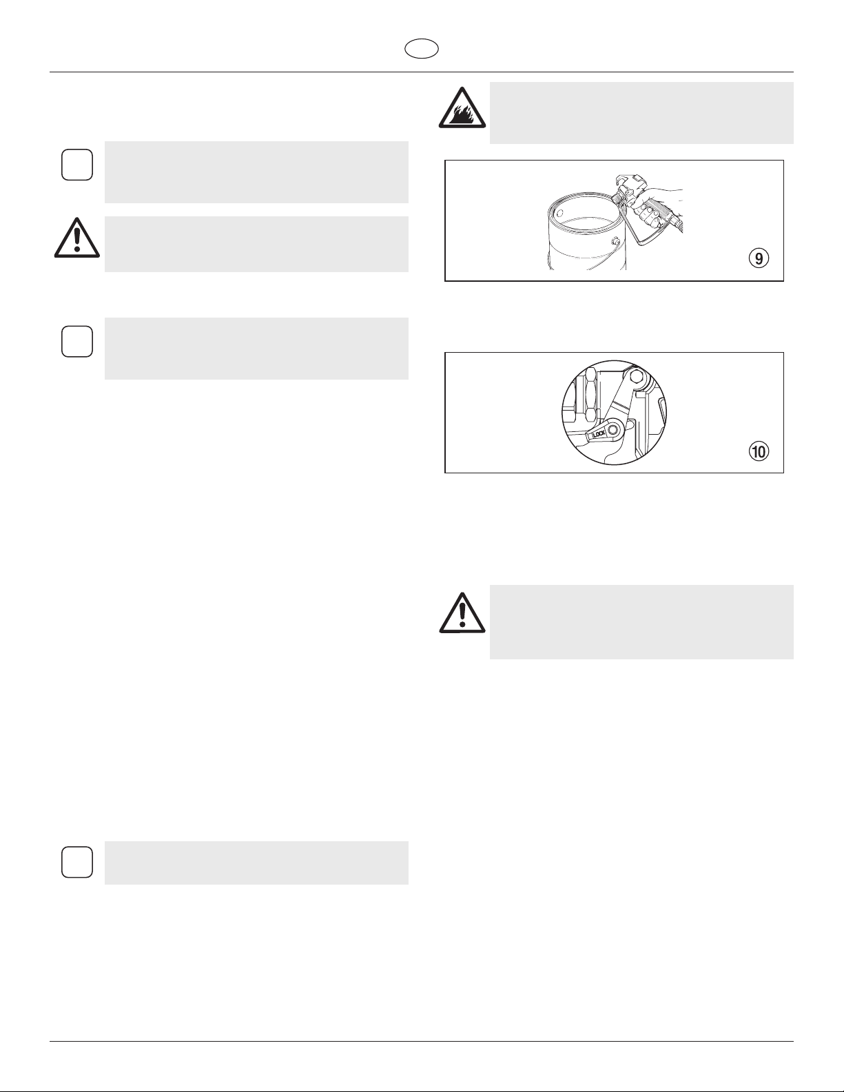
Earth the gun by holding it against the edge of the
metal container while flushing. Failure to do so may
lead to a static electric discharge, which may cause
a fire.
14. Trigger the gun into the metal waste container until the old
solvent is gone and fresh solvent is coming out of the gun.
15. Lock the gun by turning the gun trigger lock to the locked
position (g 10).
16. Set down the gun and increase the pressure by turning the
pressure control knob slowly clockwise to its highest setting.
17. Check the entire system for leaks. If leaks occur, turn the
sprayer o and follow the “Pressure Relief Procedure” in this
manual before tightening any ttings or hoses.
18. Follow the “Pressure Relief Procedure” (section 4.5) in this
manual before changing from solvent to paint.
Be sure to follow the Pressure Relief Procedure when
shutting the unit down for any purpose, including
servicing or adjusting any part of the spray system,
changing or cleaning spray tips, or preparing for
cleanup.
Make sure that the spray gun does not have a tip or
tip guard installed.
10. Close the bleed valve by turning it fully clockwise.
11. Start the engine or turn on the electric motor.
12. Turn the pressure control knob clockwise approximately 1/3
of the way down to increase pressure.
13. Unlock the gun by turning the gun trigger lock to the
unlocked position.
12 PowrTwin Plus
Page 15
GB
Operation
4.4 Painting
1. Place the siphon hose into a container of paint.
2. Place the bleed hose into a metal waste container.
3. Turn the pressure control knob fully counterclockwise to its
lowest pressure setting (g 7, 1).
4. Open the hydraulic shut-o valve (2) located on the hydraulic
pressure hose. The handle should be in line with the hose.
5. Open the bleed valve (3) by turning it fully counterclockwise.
6. Start the engine or turn on the electric motor.
a. To start the gas engine (g. 8),
• move the fuel valve lever (2) to the open position,
• move the throttle lever (3) to its middle point,
• move the choke lever (4) to the closed position for a cold
engine or to the open position for a warm engine,
• turn the engine switch (1) to the ON position, and
• pull the starter rope (5) briskly until the engine starts.
b. To start the electric motor, move the ON/OFF switch to the ON
position.
7. Turn the pressure control knob (1) clockwise approximately
1/3 of the way down to increase pressure until the sprayer
cycles evenly and solvent ows freely from the bleed hose.
8. Turn o the sprayer.
a. To turn o the gas engine,
• set the pressure to minimum by turning the pressure control
knob fully counterclockwise,
• move the throttle lever to the slow position, and
• turn the engine switch to the OFF position.
b. To turn o the electric motor,
• set the pressure to minimum by turning the pressure control
knob fully counterclockwise,
• move the ON/OFF switch to the OFF position.
9. Remove the bleed hose from the waste container and place it
into the container of paint.
10. Close the bleed valve by turning it fully clockwise.
11. Start the engine or turn on the electric motor.
12. Turn the pressure control knob clockwise approximately 1/3
of the way down to increase pressure.
13. Unlock the gun by turning the gun trigger lock to the
unlocked position.
Earth the gun by holding it against the edge of the
metal container while flushing. Failure to do so may
lead to a static electric discharge, which may cause
a fire.
19. Increase the pressure by turning the pressure control knob
slowly clockwise and test the spray pattern on a piece of
cardboard. Adjust the pressure control knob until the spray
from the gun is completely atomized.
Turning the pressure up higher than needed to
i
atomize the paint will cause premature tip wear and
additional overspray.
4.5 Pressure Relief Procedure
Be sure to follow the Pressure Relief Procedure when
shutting the unit down for any purpose, including
servicing or adjusting any part of the spray system,
changing or cleaning spray nozzles, or preparing for
cleanup.
1. Lock the spray gun by turning the gun trigger lock to the
locked position.
2. Turn o the sprayer.
a. To turn o the gas engine,
• set the pressure to minimum by turning the pressure control
• move the throttle lever to the slow position, and
• turn the engine switch to the OFF position.
b. To turn o the electric motor,
• set the pressure to minimum by turning the pressure control
• move the ON/OFF switch to the OFF position.
3. Close the hydraulic shut-o valve on the hydraulic pressure
4. Unlock the gun by turning the gun trigger lock to the
5. Hold the metal part of the gun rmly to the side of a metal
6. Trigger the gun to remove any pressure that may still be in the
7. Lock the gun by turning the gun trigger lock to the locked
8. Place the bleed hose into the metal waste container.
9. Open the bleed valve by turning it fully counterclockwise.
knob fully counterclockwise,
knob fully counterclockwise,
hose.
unlocked position.
waste container to earth the gun and avoid a build up of static
electricity.
hose.
position.
14. Trigger the gun into the metal waste container until all air and
solvent is ushed from the spray hose and paint is owing
freely from the gun.
15. Lock the gun by turning the gun trigger lock to the locked
position (g 10).
16. Turn o the sprayer.
17. Attach tip guard and tip to the gun as instructed by the tip
guard or tip manuals.
POSSIBLE INJECTION HAZARD. Do not spray
without the tip guard in place. Never trigger the
gun unless the tip is in either the spray or the unclog
position. Always engage the gun trigger lock before
removing, replacing or cleaning tip.
18. Start the engine or turn on the electric motor.
PowrTwin Plus 13
Page 16
Cleanup
i
5. Cleanup
GB
12. Start the engine or turn on the electric motor.
The sprayer, hose, and gun should be cleaned
thoroughly after daily use. Failure to do so permits
material to build up, seriously aecting the
Attention
performance of the unit.
Always spray at minimum pressure with the gun
nozzle tip removed when using mineral spirits or
any other solvent to clean the sprayer, hose, or
gun. Static electricity buildup may result in a re or
explosion in the presence of ammable vapors.
5.1 Special cleanup instructions for use with
ammable solvents
• Always ush spray gun preferably outside and at least one hose
• If collecting ushed solvents in a one gallon metal container,
• Area must be free of ammable vapors.
• Follow all cleanup instructions.
length from spray pump.
place it into an empty ve gallon container, then ush solvents.
5.2 Cleaning the sprayer
1. Follow the “Pressure Relief Procedure” found in the Operation
section of this manual, section 4.5.
2. Remove the gun tip and tip guard and clean with a brush
using the appropriate solvent.
3. Place the siphon tube into a container of the appropriate
solvent.
Earth the gun by holding it against the edge of the
metal container while flushing. Failure to do so may
lead to a static electric discharge, which may cause
a fire.
13. Trigger the gun into the metal waste container until the paint
is ushed out of the hose and solvent is coming out of the
gun.
14. Continue to trigger the spray gun into the waste container
until the solvent coming out of the gun is clean.
For long-term or cold weather storage, pump
mineral sprits through the entire system.
15. Follow the “Pressure Relief Procedure” found in the Operation
section of this manual.
16. Store the sprayer in a clean, dry area.
Do not store the sprayer under pressure.
Attention
5.3 Cleaning a Clogged Tip
1. Follow the “Pressure Relief Procedure” in the Operation
section of this manual.
2. If the tip clogs, rotate the tip handle 180° until the arrow on
the handle is facing the opposite of the spray direction and
the handle clicks in the reverse position.
Use only compatible solvents when cleaning
out oil based enamels, lacquers, coal tar, and
epoxies. Check with the uid manufacturer for the
Attention
4. Place the bleed hose into a metal waste container.
5. Set the pressure to minimum by turning the pressure control
6. Open the hydraulic shut-o valve located on the hydraulic
7. Open the bleed valve (3) by rotating the bleed valve handle
recommended solvent.
knob (1) fully counterclockwise.
pressure hose (2). The handle should be in line with the hose.
fully counterclockwise.
3
1
3. Trigger the gun once so that the pressure can blow the clog
out. NEVER use the tip in the reverse position for more than
ONE trigger pull at a time. This procedure can be repeated
until the tip is free of clogging.
The flow from the spray tip is at very high pressure.
Contact with any body part may be dangerous. Do
not place finger on gun outlet. Do not point the gun
at any person. Never operate the spray gun without
the proper tip guard.
2
8. Start the engine or turn on the electric motor.
9. Allow the solvent to circulate through the sprayer and
ush the paint out of the bleed hose into the metal waste
container.
10. Turn o the sprayer.
11. Close the bleed valve by rotating the bleed valve handle fully
clockwise.
14 PowrTwin Plus
Page 17
GB
i
i
i
Maintenance
6. Maintenance
Before proceeding, follow the Pressure Relief
Procedure outlined previously in this manual.
Additionally, follow all other warnings to reduce the
risk of an injection injury, injury from moving parts
or electric shock. Always unplug the sprayer before
servicing!
6.1 Daily Maintenance
Two daily procedures are required for routine operator maintenance
on this sprayer:
A. Lubricating the upper packings.
B. Cleaning the lter screen
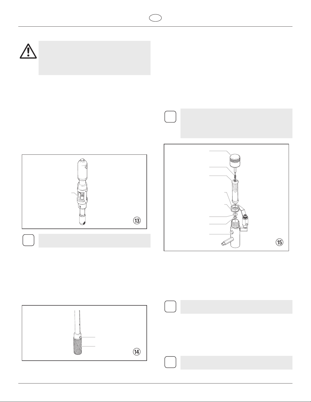
A) Lubricating the Upper Packings
1. Clean out the paint that has seeped past the upper packings
into the packing oil reservoir (g. 13, item 1) above the uid
section.
2. Fill the packing oil reservoir 1/2 full with Piston Lube (P/N 314-
480) supplied by the factory. This will extend packing life.
6.2 Maintaining the Filter Assembly
Clean the lter regularly. Dirty or clogged lters can greatly reduce
ltering ability and cause a number of system problems including
poor spray patterns, clogged spray tips, etc.
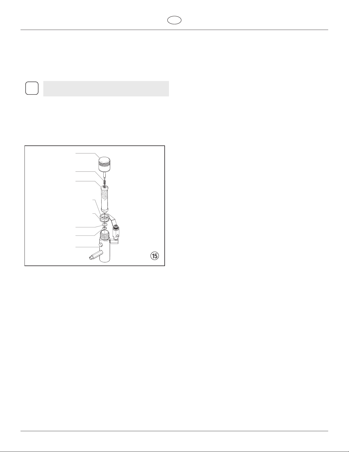
Cleaning (Fig. 15)
To clean the lter, perform the following procedure.
1. Follow the “Pressure Relief Procedure” found in the Operation
section of this manual.
2. Remove the lter cap assembly (1) and spring (2).
3. Pull the lter element with ball straight (3) out of the lter
body (4).
4. Clean inside the lter body, lter element with ball, and lter
cap assembly using the appropriate solvent.
Use care in handling parts as dirt, debris, scratches,
i
or nicks may prevent o-rings or gaskets from sealing.
This lter element lters from the inside out. Be sure
to clean the lter element thoroughly on the inside.
Soak in solvent to loosen hardened paint or replace.
1
1
Do not over-ll the reservoir so that it overows and
drips into the paint.
B) Cleaning the Filter Screen
1. The lter screen will clog and must be cleaned at least once a
day.
2. Loosen the hex nut (g. 14, item 1) that secures the lter
screen to the siphon tube.
3. Remove the lter screen (2) from the bottom of the siphon
tube.
4. Clean thoroughly with the appropriate solvent.
2
3
7
8
5
6
4
Inspection (Fig. 15)
Inspect all parts of the lter assembly before reassembly.
1. Inspect the ball inside the lter element. If the ball has
pressure cuts or scratches, replace the lter element.
a. If the ball is cut, remove the PTFE o-ring (5) using an o-ring pick
and remove the carbide seat (6).
b. Check the seat for nicks or grooves. If the seat is damaged,
replace.
Removal of the PTFE o-ring will damage the o-ring
and require replacement.
1
2
PowrTwin Plus 15
2. Remove the spring (2) from the spring guide on the lter cap.
a. Measure the length of the spring uncompressed. If it measures
less than 3/4” from end to end, replace.
b. Push the spring back onto the spring guide until it “snaps” back
into position.
3. Inspect the two PTFE gaskets (7,8) and the PTFE o-ring (5) for
deformity, nicks, or cuts. Replace, if needed.
The PTFE gaskets, PTFE o-ring, and spring are
packaged in Filter Service Kit P/N 930-050.
Page 18
Maintenance
i
Reassembly (Fig. 15)
After cleaning and inspecting all parts, reassemble the lter.
1. Place the carbide seat (6) into the lter body (4). Make sure
the beveled side of the seat is facing up.
2. Place the PTFE o-ring (5) into the groove on the outer
diameter of the carbide seat (6).
3. Place the lter element with ball (3) into the lter body (4).
The top and bottom of the lter element with ball
are identical.
4. Push the spring (2) back onto the spring guide of the lter cap
(1) until it “snaps” back into position, if not already done.
5. Place the thin PTFE gasket (8) onto the step at the top of the
lter body (4).
6. Place the thick PTFE gasket (7) onto the top of the thin gasket
(8).
7. Tighten the lter cap assembly (1) onto the lter body (4).
1
2
3
GB
7
8
5
6
4
16 PowrTwin Plus
Page 19
GB
Maintenance
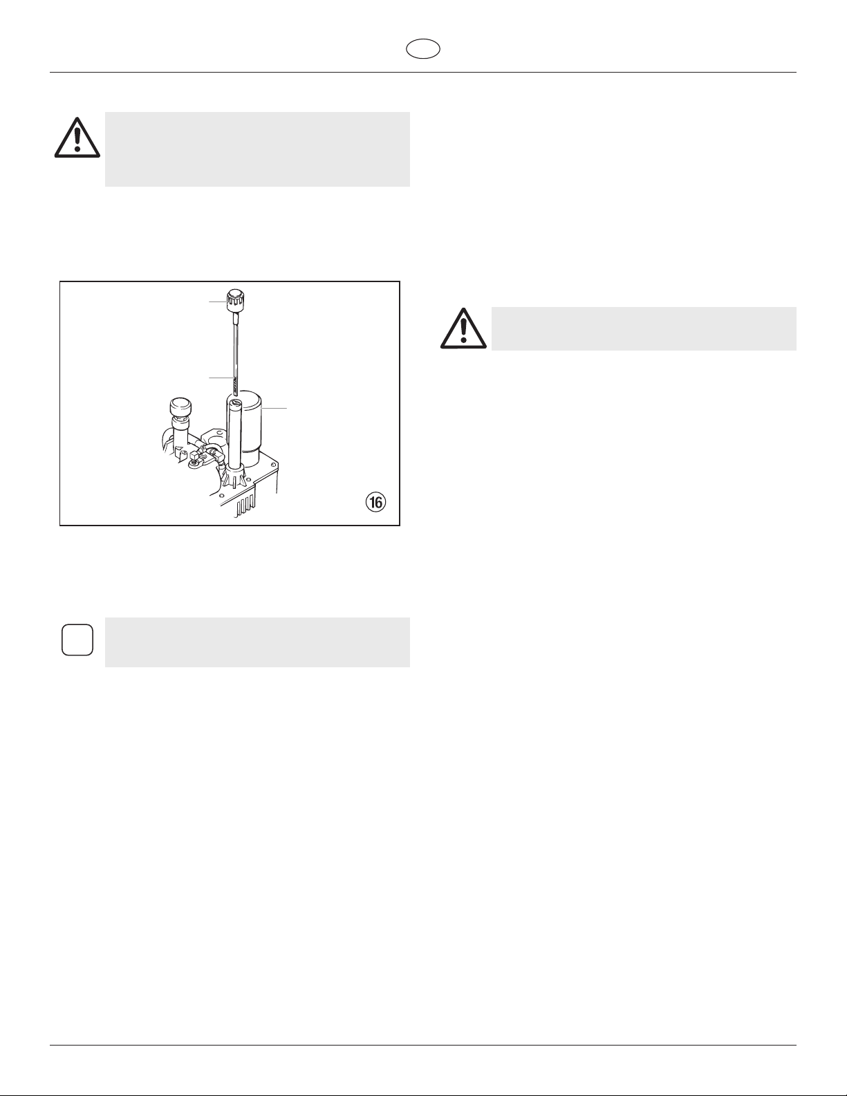
6.3 Maintaining the Hydraulic System
Use of Titan’s Coolflo™ Hydraulic Fluid is mandatory
in the PowrTwin Plus hydraulic system. Do not use
any other hydraulic fluid. Use of any other hydraulic
Attention
1. Check the hydraulic uid daily. It should be at the “Full”
fluid may seriously damage the hydraulic system
and will void the warranty.
mark (g. 16, item 1) on the dipstick (2). If it is low, add only
Titan Coolo™ Hydraulic Fluid (P/N 430-361). Never add
or change hydraulic uid except in a clean, dust-free area.
Contamination of the hydraulic uid will shorten hydraulic
pump life and may void warranty.
2
1
3
2. Change the hydraulic uid every twelve months. Drain the
old uid from the tank and ll with 6.25 quarts of hydraulic
uid. Start the sprayer at just enough pressure to operate the
uid section. Run the sprayer at this low pressure for at least
5 minutes. This removes air from the system. Check the uid
level after this procedure. Do not over-ll.
When replacing the hydraulic filter (3) during a
i
3. The hydraulic system has an external, replaceable hydraulic
4. The hydraulic pump should not be serviced in the eld. If
6.4 Maintaining the Fluid Section
If the sprayer is going to be out of service for an extended period of
time, it is recommended that following cleanup, a kerosene and oil
mixture be introduced as a preservative. Packings may tend to dry
out from lack of use. This is particularly true of the upper packing
set for which upper packing lubricant Piston Lube (P/N 314-480) is
recommended in normal usage.
If the sprayer has been out of service for an extended period of time,
it may be necessary to prime the pump with solvent. It is extremely
important that the threads on the siphon hose coupling are properly
sealed. Any air leakage will produce erratic operation of the sprayer
and may damage the system. The up and the down strokes should
be approximately equal in time (one should not be faster than the
other). A fast up or down stroke may indicate air in the system or
malfunctioning valve or seats (see the Troubleshooting section).
fluid change, it may be necessary to add up to one
additional quart of hydraulic fluid.
lter. Change the lter every twelve months.
service on the hydraulic pump is required, it must be returned
to Titan.
6.5 Basic Engine Maintenance (gas engine)
• For detailed engine maintenance and technical specications
refer to the separate gasoline engine manual.
• All service to the engine should be performed by a dealer
authorized by the engine manufacturer.
• Use a premium quality motor oil. 10W30 is recommended for
general all temperature use. Other viscosities may be required
in other climates.
• Use only a (NGK) BR-6HS (PT4900), or (NGK) BP6ES / BPR6E
spark plug (PT6900/PT8900/PT12000). Gap the plug to 0.028
to 0.031 In. (0.7 to 0.8 mm) Always use a spark plug wrench.
Daily
1. Check engine oil level, and ll as necessary.
2. Check gasoline level, and ll as necessary.
Always follow the fueling procedure outlined earlier
in this manual.
First 20 Hours
1. Change engine oil.
Every 100 Hours
1. Change engine oil.
2. Clean the sediment cup.
3. Clean and re-gap the spark plug.
4. Clean the spark arrestor.
Weekly
1. Remove the air lter cover and clean the element. In very
dusty environments, check the lter daily. Replace the
element as needed. Replacement elements can be purchased
from your local engine manufacturer dealer.
Engine Operation and Service
1. Clean and oil air lter pad on gasoline engine every 25 hours
or once weekly. Do not permit the air intake screen around
the y wheel of the gas engine to load up with paint or
trash. Clean it regularly. The service life and eciency of
the gas engine model depends upon keeping the gasoline
engine running properly. Change the oil in the engine
every 100 hours. Failure to observe this may result in engine
overheating. Consult the engine manufacturer’s service
manual provided.
2. To conserve fuel, service life, and eciency of the sprayer,
always operate the gasoline engine at the lowest RPM at
which it runs smoothly without laboring and delivers the
amount required for the particular painting operation.
Higher RPM does not produce higher working pressure. The
gasoline engine is connected to the hydraulic pump by a
pulley combination designed to produce full paint delivery at
maximum RPM.
3. The warranty on gasoline engines or electric motors is limited
to the original manufacturer.
PowrTwin Plus 17
Page 20
Maintenance
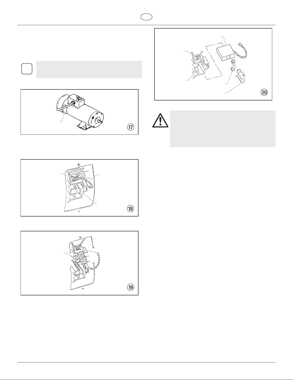
6.6 Replacing the Motor Brushes (optional 120V
electric motor)
The 120V electric Convertokit is available for separate purchase.
Perform this procedure using Motor Brush Kit P/N 978-050. The kit
consists of two brushes, two springs, and two clips.
Brushes should be replaced when they are worn to
i
1. Remove both inspection covers (1) on the motor.
less than 1/2 inch. Check and replace both brushes
at the same time.
1
2. Push in the spring clip (2) to unhook it, then pull it out.
3. Loosen the terminal screw (3). Pull the brush lead (4) away,
but leave the motor lead in place. Remove the brush and
spring.
GB
8
7
7. Reinstall both inspection covers.
If electric motor overloads and stops running,
IMMEDIATELY turn the motor off and follow
the Pressure Relief Procedure in the Cleanup
section of this manual. Wait until the motor cools
(approximately 30 minutes). Then push in the
bubble top, manual reset button, turn the motor on
and pressurize the system.
6
9
2
3
4
2
4. Inspect the commutator (5) for burning, excessive pitting or
gouging. A black color on the commutator is normal.
5
5. Install the new brush (6) so its lead slides in the long slot of the
brush holder (7). Push the terminal under the terminal screw
washer (8). Ensure the motor lead is still connected at the
screw. Tighten the screw.
6. Place the spring (9) on the brush (6) as shown above. Push
in and hook the spring clip (2). Repeat this procedure for the
other side.
18 PowrTwin Plus
Page 21
GB
Attention
Maintenance
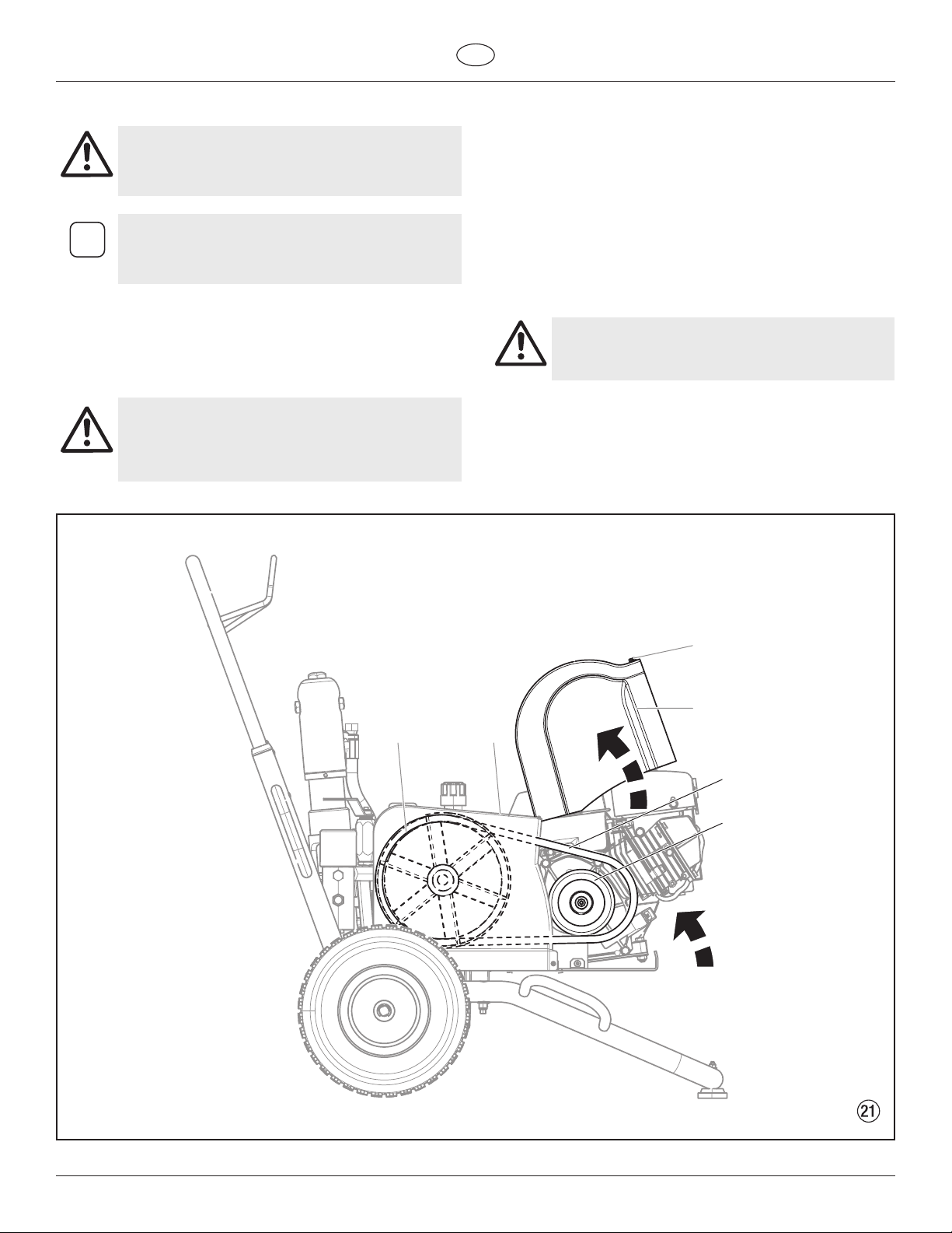
6.7 Replacing the Belt (Fig. 21)
Before replacing the belt on your unit, make sure
you have performed the “Pressure Relief Procedure”
as illustrated in the Operation section of this manual.
DO NOT attempt this repair while the unit is running.
The graphics below show a unit with a gas engine.
All instructions given in this section will apply to
i
both gas engine models and electric motor models
except where noted.
1. Loosen the bolt (1) on the front of the belt guard. Lift open
the front end of the belt guard (2) so that the front end of the
belt (3) is exposed.
2. Gently lift the front end of the gas engine / electric motor.
This will loosen the tension on the belt and make it easier to
remove.
PINCH HAZARD. Make sure your fingers remain clear
of the gas engine / electric motor mounting plate.
BURN HAZARD. Make sure the gas engine has had
time to sufficiently cool before touching it.
3. While the gas engine / electric motor is lifted up, remove the
belt from the front (4) and rear (5) pulleys.
4. Install the new belt:
a. Insert the belt into the xed section of the belt guard (6). Loop
the belt over the rear pulley (5) until the belt engages the
pulley groove.
b. Gently lift the front end of the gas engine / electric motor.
c. With the front end of the gas engine / electric motor lifted, loop
the other end of the belt around the front pulley (4).
d. Gently set the the gas engine / electric motor down. The
weight of the gas engine / electric motor will create tension in
the belt and prevent it from coming o.
Make sure the belt is not pinched or twisted in any
way once you have set the gas engine / electric
motor back into place.
e. Close the belt guard (2) and tighten the belt guard bolt (1).
5 6
1
2
3
4
PowrTwin Plus 19
Page 22
Maintenance
GB
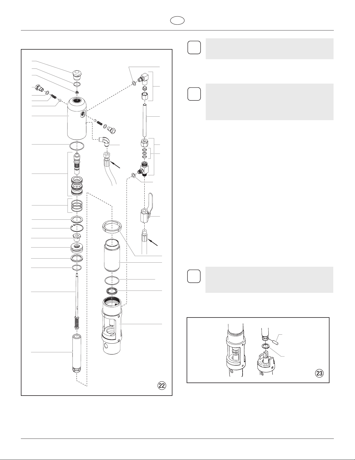
6.8 Servicing the Hydraulic Motor (Fig. 22)
1
2
3
4
5
6
7
8
9
10
11
12
13
14
15
16
17
18
20
(A)
21
9
(B)
21
22
23
24
25
26
28
29
30
Refer to the ”SAE O-Ring Fitting Installation”
i
Perform this procedure using the necessary parts from Motor Service
Kit — Minor (P/N 235-050). If the hydraulic motor is operable, start
the machine and jog the piston rod (19) into its top position.
i
procedure at the end of this section for installation
instructions for item 22.
Servicing of the hydraulic motor should be carried
out in a clean, dust free area only. Any dust or
metallic particles left in the motor or entering it on
reassembly may damage the critical parts and aect
its service life and warranty. All parts should be
inspected for absolute cleanliness.
Disassembling the Hydraulic Motor
1. Disconnect the pressure hose assembly (B) from the elbow
(34 and 35 in Hydraulic System parts list) on the back of the
hydraulic pump.
2. Remove the two mounting screws and two lock washers (17
and 16, in Cart Assembly parts list) that attach the motor/
pump assembly to the cart.
3. Place the motor/pump assembly in a vise, holding it securely
by the motor/pump block (31).
4. Remove cylinder head plug (1).
5. Loosen lock ring (28) with a spanner wrench and unthread
tube retaining nut on tee (24). Loosen tube retaining nut on
elbow (22). Slide the nut down. Push motor tube (23) into tee
(24) far enough to clear elbow (22). Slowly unthread cylinder
head (8) and Iift it just high enough above the cylinder (29) to
reach the valve rod assembly (18) with vise grip pliers.
6. The piston rod (19) should be near the top of its stroke for
disassembly. It may be necessary to use a wood or nylon driver
to push the piston rod up to its top position.
7. Grip the valve rod securely with vise grip pliers and then
remove the FlexLoc nut (3) from the top of the valve rod
assembly (18). Be careful that spool (10) does not fall. The
cylinder head (8) can now be lifted o. Unthread the cylinder
(29) from the motor/pump block (31).
An extra lock ring (28) can be used to jam the two
i
8. To remove the connecting pin (Fig. 23, 1), slide the retaining
lock rings together on the cylinder and a pipe
wrench can be used to unthread the cylinder (29)
from the motor/pump block.
ring (2) down with a small screwdriver, and then push the
connecting pin out.
31
1
19
9. Remove the piston rod assembly from the motor/pump block
(31).
10. Remove rod seal (30), being extremely careful not to scratch
the seal groove in the motor/pump block (31).
11. Place the piston retainer screw (14) on the piston rod assembly
in a vise. Slide a long bar through the hole at the base of the
piston rod for leverage, and unthread the piston rod from the
piston retainer screw.
12. Remove piston (19) and lift out valve rod assembly (18).
20 PowrTwin Plus
2
Page 23
GB
Attention
Maintenance
13. Remove piston seal (16) and o-ring (17).
14. Remove trip retainers (4), trip springs (6), and balls (7) from
cylinder head (8). Remove o-rings (5) from trip retainers.
15. Remove retaining ring (13) and sleeve retainer (12). Gently tap
spool/sleeve set (10) out of cylinder head (8) using a wood or
nylon rod.
16. Inspect piston rod (19) and cylinder (29) for wear, scratches,
and dents. Replace if damaged.
17. Inspect spool valve (10) for wear. Replace if necessary. spool
valve should move smoothly and freely with no force by
holding in a vertical position. If it does not, it can cause the
motor to stall.
Reassembling the Hydraulic Motor
1. Separate spool/sleeve set (10). Place o-rings (11) onto sleeve.
Lubricate o-rings with hydraulic oil. Gently push the sleeve
into cylinder head (8) with the atter side of the sleeve facing
out. Use a nylon rod to tap sleeve down until it reaches its full
depth. Do not use any other type of tool that might damage
or leave particles or residue on the sleeve. Install the spool
through the top of the cylinder head, down into the sleeve.
Do not use Piston Lube pump packing lubricant. It is
a solvent and will severely damage seals and O-Rings
of the hydraulic motor.
2. Install o-rings (5) on trip retainers (4). Install trip retainer balls
(7) followed by springs (6) which, when installed, will hold
spool/sleeve set (10) in proper place for assembly.
3. Install sleeve retainer (12) followed by retainer ring (13) into
cylinder head (8), which will hold valve sleeve in place. Install
o-ring (9) in the o-ring groove of the cylinder head.
4. Replace rod seal (30) in motor/pump block (31). Be sure the
open portion of the seal is facing upward (V). This seal requires
no special tool.
5. Place piston rod (19) in vise. Inspect valve rod assembly (18)
for any damage. Make sure the lock nut at the bottom of the
valve rod assembly is secure. DO NOT remove. Then, place into
piston rod as illustrated. Install o-ring (17), lubricating it well
and replacing piston (15) onto piston rod (19). Put one drop of
blue Loctite on the piston retainer screw (14). Tighten piston
retainer screw until piston is locked into place. Check valve rod
assembly for normal spring action at this time.
6. Install piston seal (16) with lips facing downward. Carefully
install o-ring (17). Expand the ring and stretch it suciently for
installation.
7. With motor/pump block (31) still in vise, install rod seal (30)
by pushing it towards its groove with a properly sized blunt
rod. Then complete installation with the ngers. No tool is
necessary. Do not twist the seal.
8. Pre-lubricate the piston and valve rod assembly with Coolo™
hydraulic uid (P/N 430-361). Install piston rod (19) into
motor/pump block (31) with a gently pushing and rotating
motion to work the piston rod in through the rod seal (30).
rod pass through the top of the spool/sleeve set (10). The
valve rod threads must be clean and free of oil. Place one drop
of blue Loctite on threads of ex lock nut (3) and thread nut
onto valve rod to full tight position (do not over-tighten) while
holding valve rod below with vise grip pliers.
13. Thread cylinder head (8) down onto the cylinder (29) and
then back o just enough to reassemble hydraulic ttings and
motor tube (23). Tighten lock ring with spanner wrench to
hold cylinder head in position.
14. The tee assembly (24) and the elbow (22) use an o-ring (25) to
seal on the outer diameter (O.D.) of the motor tube (23). The
O.D. of the motor tube should be free of scratches or sharp
edges. The lock nuts on these ttings rst should be hand
tightened, then wrench tightened another half turn.
15. Install o-ring (2) onto cylinder head plug (1). Tighten.
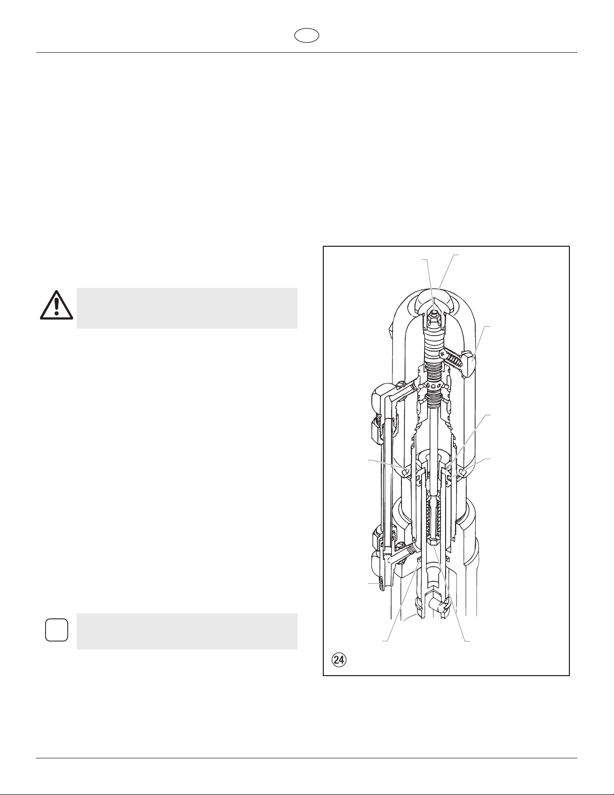
Hydraulic Motor Cut-Away
Torque ex locknut to
40 in./lbs. (4.5 Nm).
Use blue Loctite.
Use blue
Loctite on
lock ring.
Use
hydraulic
sealant.
Torque head plug to
15 ft./lbs. (22 Nm).
Do not over-tighten
o-ring seal.
Torque trip
retainers to
8 ft./lbs. (10.8 Nm).
Do not over-tighten
o-ring seal.
Torque piston
retainers to
40 ft./lbs. (55 Nm).
Use red Loctite.
Seal lip must
face down.
Inspect the bottom of piston rod (19) for nicks or
sharp areas that could damage the piston seal during
i
installation through the motor/pump block (31).
9. Replace the connecting rod pin and retainer ring.
10. Install o-ring (9) on cylinder wall. Lubricate ring and inner wall.
With the piston rod held rmly, the cylinder should be gently
driven over the piston seal with a rubber mallet. Tightly thread
the cylinder into motor/pump block (31).
11. Raise piston rod (19) to top position and thread lock ring (28)
all the way up on upper threads of cylinder (29).
12. Pull valve rod assembly (18) up as far as it will travel and grasp
it with vise grip pliers. Then install cylinder head (8), already
assembled, over valve rod until the top threads of the valve
PowrTwin Plus 21
Seal lip must
face up.
Valve rod assembly
is factory set and
permanently Loctited.
Do not disassemble.
Page 24
GB
Maintenance
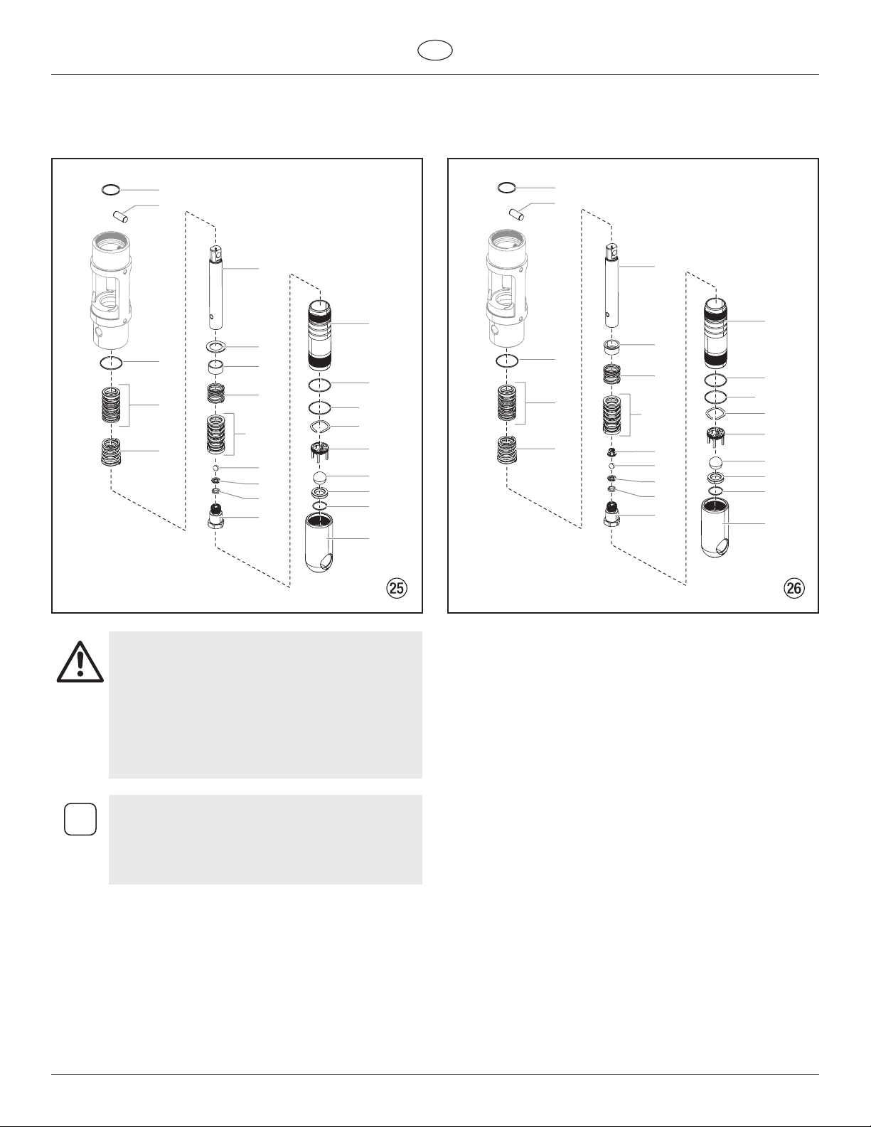
6.9 Servicing the Fluid Section
PT4900 Plus PT6900 Plus / PT8900 Plus / PT12000 Plus
1
2
6
14
7
3
4
5
8
9
4
10
11
12
13
15
3
21
16
17
18
19
20
1
2
6
14
7
3
8
4
5
4
9
10
11
12
13
15
3
16
17
18
19
20
21
Attention
i
Use of non-Titan service parts may void warranty.
Ask for original parts made by Titan for best services.
This pump should receive a routine servicing after
approximately 1,000 hours of use. Earlier servicing
is required if there is excessive leakage from the top
packing or if pump strokes become faster on one
stroke or the other. The use of Titan Piston Lube
(P/N 314-480) is recommended as an upper packing
lubricant. Do not substitute oil, water, or solvent for
an upper packing lubricant.
Numbers in parentheses refer to the item numbers
in the fluid section illustrations. If there are two
numbers, the first number represents the item
number for the PT4900 Plus and the second number
represents the item number for the PT6900 Plus /
PT8900 Plus / PT12000 Plus.
Disassembling the Fluid Section
1. Remove the siphon hose assembly. Unthread the foot valve
housing (20,21) and the pump cylinder (14) with a strap
wrench.
2. Slide the retainer ring (1) up with a small screwdriver, then
push the connecting pin (2) out.
3. Pull the displacement rod (6) through the lower cavity of the
motor/pump block.
4. Remove the PTFE o-ring (3), upper packing spring (5), and
upper packing set (4) from the motor/pump block.
5. Hold the displacement rod (6) in a vise by the ats at the top
of the displacement rod and remove the outlet valve housing
(13) with a wrench while holding the displacement rod
horizontal with wooden support, if necessary. Remove the
seal washer (12), outlet valve seat (11), outlet valve ball (10),
outlet valve cage (9, PT6900/PT8900/PT12000) lower packing
set (4), lower packing spring (9,8), sleeve (8, PT4900 only), and
spring retainer (7).
6. Using a 1/2” extension bar attached to a 1/2” drive ratchet,
insert the end of the extension bar into the square opening
of the foot valve cage (16,17) inside the foot valve housing
(20,21). Unscrew and remove the foot valve cage along with
the wave washer (21,16) from the foot valve housing.
7. Remove the PTFE o-ring (3), foot valve ball (17,18), foot
valve seat (18,19), and seat o-ring (19,20) from the foot valve
housing (20,21).
8. Remove the o-ring (15) from the pump cylinder (14)
22 PowrTwin Plus
Page 25
GB
i
i
Maintenance
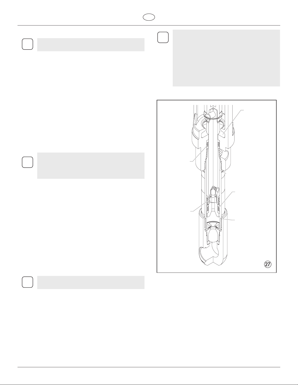
Reassembling the Fluid Section
Use PTFE tape on all threaded pipe connections.
1. Place a new seat o-ring (19,20) into the groove in the bottom
of the foot valve housing (20,21).
2. Inspect the foot valve seat (18,19) for wear. If one side is worn,
ip the seat to the unused side. If both sides are worn, install a
new seat. Place the new or ipped seat (worn side down) into
the bore at the bottom of the foot valve housing (20,21).
3. Place a new foot valve ball (17,18) onto the foot valve seat
(18,19). Using a 1/2” extension bar attached to a 1/2” drive
ratchet, insert the end of the extension bar into the square
opening of the foot valve cage (16,17) and screw the foot
valve cage into the foot valve housing (20,21). Torque the
cage to 240 in./lbs. (20 ft./lbs.).
4. Place the wave washer (21, 16) on top of the foot valve cage
(16,17).
5. Insert a new PTFE o-ring (3) into the groove of the foot valve
housing (20,21). Lubricate the o-ring using oil or grease.
6. After soaking the leather packings in oil (preferably linseed
oil), reassemble the lower packing set (4). Place the set onto
the outlet valve housing (13) with the peak of the “V” packings
pointing down toward the hex on the outlet valve housing.
All leather packings must be soaked in CoolFlo
hydraulic oil for 15–20 minutes before installation.
i
Soaking the packings too long will cause the
packings to swell and create diculty during
reassembly.
It is not necessary to over-tighten the foot valve
i
housing. O-ring seals perform sealing function
without excessive tightening. Full thread
engagement is sufficient. The foot valve housing
may be rotated backward up to 1/2 turn from full
engagement for convenient hose position.
For siphon hose attachment, it is critically important
that the threads of the siphon hose fit snugly into
the foot valve housing with the hose assembly
couplings PTFE taped and sealed to prevent air
leakage.
Fluid Section Cut-Away
Peaks of upper
packings must
face up.
Oil cup area
for piston lube
packing
lubricant.
7. Inspect the outlet valve seat (11) for wear. If one side is worn,
ip the seat to the unused side. If both sides are worn, use
a new seat. Insert the outlet valve cage (9, PT6900/PT8900/
PT12000) outlet valve ball (10), new or ipped seat (worn
side away from ball), and a new seal washer (12) into the
displacement rod (6).
8. Clean the threads on the outlet valve housing (13) and coat
the threads with blue Loctite #242. Make sure the Loctite is
only on the threads.
9. Place the lower packing spring (9,8) onto the outlet valve
housing (13) followed by the sleeve (8, PT4900 only) and
spring retainer (7).
10. Screw the displacement rod (6) and the outlet valve housing
(13) together. Tighten in a vise to 600 in./lbs. (50 ft./lbs.).
11. Insert the PTFE o-ring (3) into the upper grove of the motor/
pump block.
12. Insert the upper packing set (4) into the motor/pump block
with the peak of the “V” packings pointing up toward the
motor.
The packings must be soaked in CoolFlo hydraulic oil
before installation.
13. Place the upper packing spring (5) into the motor/pump block
with the small tapered end facing up toward the motor/pump
block.
14. Insert the displacement rod (6) up through the upper packings
in the motor/pump block.
15. Align the holes in the displacement rod (6) and the hydraulic
piston rod and insert the connecting pin (2). Replace the
retaining ring (1) over the connecting pin.
16. Thread the short threads of the pump cylinder (14) into the
motor/pump block and tighten with a strap wrench.
17. Place the o-ring (15) onto the top grove of the pump cylinder
(14).
18. Thread the foot valve housing (20,21) onto the pump cylinder
(14), tighten with a strap wrench and then back o to align the
siphon hose.
Torque outlet
valve housing
to 50 ft./lbs.
(68 Nm).
Use blue
Loctite.
Peaks of lower
packings must
face down.
Lubricate O-ring.
PowrTwin Plus 23
Page 26
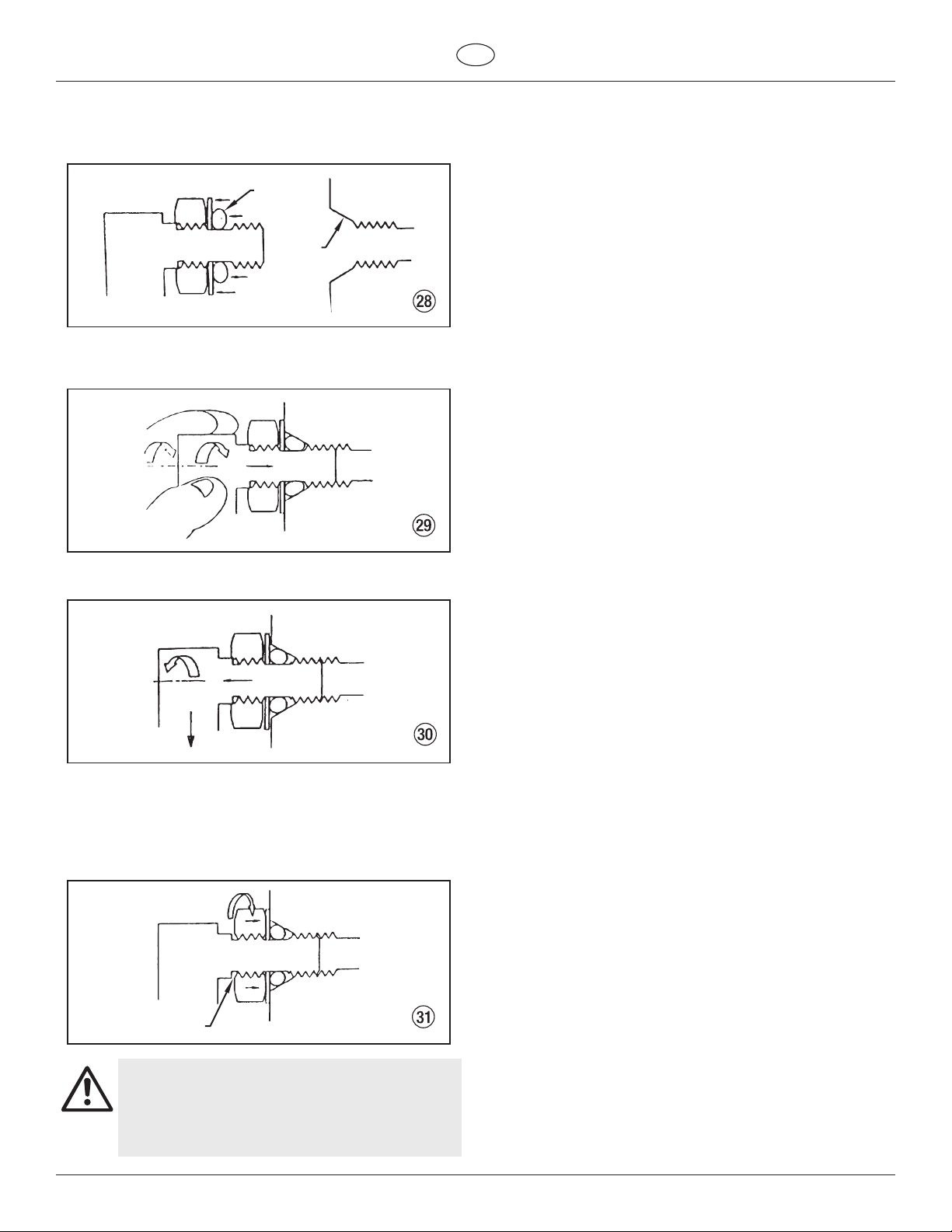
Maintenance
6.10 SAE O-Ring Fitting Installation
1. Pull washer and o-ring back as far as possible.
2. Lubricate o-ring (1) and entrance port (2).
1
2
3. Screw tting in until washer pushes o-ring into entrance and
sits at against port. (Do not tighten! - only do this step hand
tight to compress o-ring into port!)
GB
4. Back tting out no more than one complete turn to align as
required.
5. Torque nut wrench tight holding backup on tting (3). This
should expose a recess gap (4) behind the nut which can act
as an indicator that the tting is assembled correctly. (This is a
feature for a specic version of this tting only - which screws
into the cylinder head. Other ttings, as the ones which attach
to the hydraulic pump, assemble the same but may not have
the indicator.)
3
4
Avoid screwing in the fitting too far. This can cause
the washer to bend, which will cause the O-ring to
Attention
24 PowrTwin Plus
extrude.
Avoid leaving the fitting out too far. This can lead to
the O-ring being cut on the threads of the fitting.
Page 27

GB
Troubleshooting
7. Troubleshooting
7.1 Airless Gun
Problem
A. Spitting gun
B. Gun will not shut o
C. Gun does not spray
7.2 Fluid Section
Problem
A. Pump delivers on upstroke only
or goes up slowly and down fast
(commonly called downstroke
dive)
B. Pump delivers on down stroke
only or goes up fast and down
slowly
C. Pump moves up and down fast,
delivering material
D. Pump moves up and down
slowly when spray gun is shut
o
E. Not enough uid pressure at
gun
F. Pump chatters on up or down
stroke
Cause
1. Air in system
2. Dirty gun
3. Needle assembly out of adjustment
4. Broken or chipped seat
1. Worn or broken needle & seat
2. Needle assembly out of adjustment
3. Dirty gun
1. No paint
2. Plugged lter or tip
3. Broken needle in gun
Cause
1. Lower foot valve ball is not seating due to
trash or wear
2. Material too viscous to siphon.
3. Air leaking in on siphon side or damaged
siphon hose. Siphon may be too small for
heavy material.
1. Upper ball is not seating due to trash or wear
2. Lower packing set is worn
1. Material container is empty or material is too
thick to ow through siphon hose
2. Bottom ball stuck to foot valve seat
3. Siphon hose is kinked or loose
1. Loose connections. Bleed valve is open
partially or bleed valve is worn. Lower
packing seat is worn.
2. Upper and/or lower ball not seating
1. Spray tip is worn
2. Outlet lter or gun lter is clogged
3. Low voltage and/or inadequate amperage
4. Hose size or length is too small or too long
1. Solvent has caused upper packing to swell
Solution
1. Inspect connections for air leaks.
2. Disassemble and clean.
3. Inspect and adjust.
4. Inspect and replace.
1. Replace.
2. Adjust.
3. Clean.
1. Check uid supply.
2. Clean.
3. Replace.
Solution
1. Remove foot valve assembly. Clean and inspect. Test
foot valve by lling with water; if ball fails to seal the
seat, replace ball.
2. Thin material — contact manufacturer for proper
thinning procedures.
3. Tighten all connections between pump and paint
container. If damaged, replace. Switch to larger diameter
siphon set.
1. Check upper seat and ball with water. If ball fails to seal,
replace seat.
2. Replace packing set if worn.
1. Rell with new material. If too thick, remove siphon
hose, immerse uid section in material, and start pump
to prime. Add thinner to material. Change to bigger
siphon set. Open bleed valve to remove air and restart
pump.
2. Remove foot valve. Clean ball and seat.
3. Straighten.
1. Check all connections between pump and gun. Tighten
as necessary. If material is owing from bleed hose, close
bleed valve or replace, if necessary. Should none of the
above be evident, replace lower packing.
2. Reseat balls by cleaning.
1. Replace.
2. Clean or replace lter.
3. Check electrical service. Correct as required.
4. Increase hose size to minimize pressure drop through
hose and/or reduce hose length.
1. Replace packing.
PowrTwin Plus 25
Page 28

Troubleshooting
7.3 Hydraulic Motors
GB
Problem
A. Oil motor stalls at bottom (no
unusual heat problems)
B. Oil motor stalls at top (no
unusual heat problems)
C. Low pressure (okay on down
stroke, sluggish on up.stroke —
high heat)
Note: Engine labors on upstroke, idles
back at stall on the down stroke.
D. Low pressure (both strokes -
high heat)
Note: Engine labors at stall on both
strokes.
Cause
1. Fluid pump piston seat unthreaded
2. Valve sticking or oil motor trip rod shifter
assembly separated
1. Valve sticking
2. Broken spring retainer (valve rod assembly)
3. Broken spring or valve rod
4. Air in hydraulic motor
5. Air in uid pump
1. Blown piston seal
2. Cracked piston
1. Blown center o-rings on spool valve
2. Bad hydraulic pump
Solution
1. If connecting rod is okay, remove cylinder head plug
and pop valve down. Replace plug and start machine.
If machine cycles up and stops at bottom again, then
problem is piston seat on uid pump. Check piston seat.
Repair or replace as necessary. If piston seat is okay and
problem does not change, check oil motor.
2. Remove valve and check for scratches and rough
movement when sliding it up and down. Replace valve
and spool in this condition. Check trip rod for possible
separation.and spool in this condition. Check trip rod for
possible separation.
1. Remove valve and check for scratches and rough
movement when sliding it up and down. Replace valve
and spool in this condition.
2. Replace valve rod assembly.
3. Replace valve rod assembly.
4. Reset valve. Purge Air, generally accomplished by low
pressure cycling of motor/pump assembly for 5–10
minutes. Check for causes of air introduction:
• Loose ttings in tank.
• Loose ttings on hydraulic pump.
• Loose hose connections.
• Low oil in reservoir.
5. Stall at top can occur randomly when uid pump picks
up air. Reset valve. Avoid air in the uid pump.
1. Before dismantling oil motor, start machine. With pump
cycling under pressure, touch the hydraulic cylinder and
the head to see if cylinder or head gets hotter. This will
help determine if piston seal is blown or piston nut is
broken. If heat is on the head, check the o-rings on spool
valve.
2. Dismantle oil motor and check piston seals cylinder bore
and piston nut. Pay special attention to piston nut. It can
be cracked and not show externally.
1. Before dismantling oil motor, start machine. With pump
cycling under pressure, touch the head to see if the head
becomes hotter. This will help determine if center o-ring
is blown on spool valve. If hot, remove and replace
o-ring.
2. Replace hydraulic pump.
26 PowrTwin Plus
Page 29
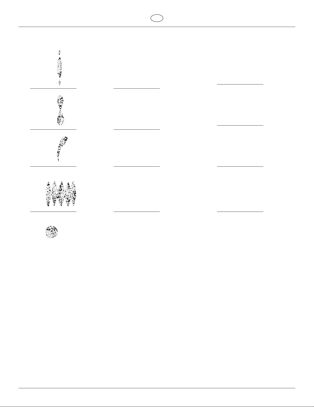
GB
Troubleshooting
7.4 Spray Patterns
Problem
A. Tails
B. Hour glass
C. Distorted
D. Pattern expanding and
contracting (surge)
Cause
1. Inadequate uid delivery
1. Inadequate uid delivery
1. Plugged or worn nozzle tip
1. Suction leak
2. Pulsating uid delivery
Solution
1. Fluid not atomizing correctly:
Increase uid pressure. Change to smaller tip orice size.
Reduce uid viscosity. Reduce hose length. Clean gun
and lter(s). Reduce number of guns using pump.
1. Same as above.
1. Clean or replace nozzle tip.
1. Inspect for suction hose leak.
2. Change to a smaller tip orice size. Install pulsation
dampener in system or drain existing one. Reduce
number of guns using pump. Remove restrictions in
system; clean tip screen if lter is used.
E. Round pattern
1. Worn tip
2. Fluid too heavy for tip
1. Replace tip.
2. Increase pressure. Thin material. Change nozzle tip.
PowrTwin Plus 27
Page 30
Übersetzung der Originalbetriebsanleitung
Warnung!
Achtung: Verletzungsgefahr durch Injektion!
Airless-Geräte entwickeln extrem hohe Spritzdrücke.
Niemals Finger, Hände oder andere Körperteile mit dem
Spritzstrahl in Berührung bringen!
1
Nie die Spritzpistole auf sich, Personen und Tiere richten.
Nie die Spritzpistole ohne Spritzstrahl-Berührungsschutz
benutzen.
Behandeln Sie eine Spritzverletzung nicht als harmlose Schnittver-
letzung. Bei einer Hautverletzung durch Beschichtungssto
oder Lösemittel sofort einen Arzt aufsuchen zur schnellen,
fachkundigen Behandlung. Informieren Sie den Arzt über den
verwendeten Beschichtungssto oder das Lösemittel.
D
2
3
Vor jeder Inbetriebnahme sind gemäß Betriebsanleitung folgende
Punkte zu beachten:
1. Fehlerhafte Geräte dürfen nicht benutzt werden.
2. Titan-Spritzpistole sichern mit Sicherungshebel am Abzugsbügel.
3. Erdung sicherstellen.
4. Zulässigen Betriebsdruck von Hochdruckschlauch und Spritzpistole
überprüfen.
5. Alle Verbindungsteile auf Dichtheit prüfen.
Anweisungen zur regelmäßigen Reinigung und Wartung des
Gerätes sind streng einzuhalten.
Vor allen Arbeiten am Gerät und bei jeder Arbeitspause folgende
Regeln beachten:
1. Spritzpistole und Hochdruckschlauch druckentlasten.
2. Titan-Spritzpistole sichern mit Sicherungshebel am Abzugsbüge.
3. Gerät ausschalten.
Achte auf Sicherheit!
28 PowrTwin Plus
Page 31

D
Inhalt
Inhalt
Seite
1. Sicherheitsvorschriften für das Airless-Spritzen .................30
1.1 Erklärung der verwendeten Symbole ............................................ 30
1.2 Elektrische Sicherheit ........................................................................... 31
1.3 Benzinmotoren-Betriebssicherheit ................................................. 32
1.4 Betanken (Benzinmotor) ..................................................................... 32
2. Anwendungsübersicht ..................................................................... 33
2.1 Einsatzgebiete ........................................................................................ 33
2.2 Beschichtungsstoe ............................................................................. 33
3. Gerätebeschreibung .........................................................................33
3.1 Airless-Verfahren ................................................................................... 33
3.2 Funktion des Gerätes ........................................................................... 33
3.3 Erklärungsbild PT-Geräte mit Benzinmotor ................................ 34
3.4 Erklärungsbild PT-Geräte mit Elektromotor ................................ 35
3.5 Technische Daten PT-Geräte ............................................................. 36
3.6 Empfehlungstabelle für Airless Spritzdüse ................................. 37
4. Bedienung .............................................................................................. 38
4.1 Einrichtung .............................................................................................. 38
4.2 Vorbereitung eines neuen Spritzgeräts ........................................ 39
4.3 Vorbereitung der Farbe.......................................................................40
4.4 Farbgebung ............................................................................................. 41
4.5 Vorgehensweise bei Druckentlastung ..........................................41
5. Reinigung ...............................................................................................42
5.1 Besondere Reinigungshinweise bei Verwendung
entflammbarer Lösungsmittel ..........................................................42
5.2 Reinigung des Spritzgeräts ................................................................ 42
5.3 Eine verstopfte Düse reinigen .......................................................... 42
Seite
7. Fehlerbehebung .................................................................................. 53
7.1 Airless-Spritzpistole .............................................................................. 53
7.2 Flüssigkeitsbereich ............................................................................... 53
7.3 Hydraulikmotor ...................................................................................... 54
7.4 Spritzmuster ............................................................................................ 55
Zubehör und Ersatzteile ................................................................................ 84
Ersatzteilliste Hauptbaugruppe .............................................................. 84/85
Ersatzteilliste Wagen ................................................................................... 86/87
Ersatzteilliste Hydrauliksystem ................................................................ 88/89
Ersatzteilliste Hydraulikmotor ................................................................. 90/91
Ersatzteilliste Flüssigkeitsbereich • PT4900 ......................................... 92/93
Ersatzteilliste Flüssigkeitsbereich •
PT6900 / PT8900 / PT12000 ...................................................................... 94/95
Ersatzteilliste Convertokit, Benzinmotor ............................................. 96/97
Ersatzteilliste Convertokit, Elektromotor (230V) ............................... 98/99
Ersatzteilliste Hochdrucklter .......................................................................100
Ersatzteilliste Keilriemenbaugruppe ..........................................................101
Ersatzteilliste Ablassschlauchbaugruppe mit Ventil ............................102
Ersatzteilliste Ablassschlauchbaugruppe .................................................103
Ersatzteilliste Syphonschlauchbaugruppe ..............................................104
Schaltplan (230V) ............................................................................................105
Zubehör für PT-Geräte .................................................................................106
Pistolenmehrfachanschluss (Optional) .....................................................108
Garantie ...............................................................................................................109
6. Unterhalt ................................................................................................. 43
6.1 Tägliche Wartung .................................................................................. 43
6.2 Unterhalt des Filteraufbaus ............................................................... 43
6.3 Unterhalt des hydraulischen Systems ...........................................45
6.4 Unterhalt des Flüssigkeitsbereichs ................................................. 45
6.5 Einfacher Unterhalt des Motors (Benzinmotor) ......................... 45
6.6 Auswechseln der Motorbürsten
(optional 120 V elektrischer Motor) ................................................ 46
6.7 Auswechseln des Riemens ................................................................. 47
6.8 Wartung des Hydraulikmotors ......................................................... 48
6.9 Unterhalt des Flüssigkeitsbereiches ............................................... 50
6.10 Montageanleitung zum SAE O-Ring ..............................................52
PowrTwin Plus 29
Page 32

Sicherheitsvorschriften
i
1. Sicherheitsvorschriften für das AirlessSpritzen
1.1 Erklärung der verwendeten Symbole
Diese Bedienanleitung enthält Informationen, die der Benutzer vor
Verwendung des Geräts gründlich durcharbeiten muss. In Bereichen,
die mit den folgenden Symbolen gekennzeichnet sind, besonders
vorsichtig arbeiten und alle Sicherheitshinweise beachten.
Dieses Symbol verweist auf eine potenzielle
Gefahr, die zum Tode oder zu schweren
Verletzungen führen kann. Hier finden Sie
wichtige Sicherheitsinformationen.
Dieses Symbol weist auf eine potenzielle Gefahr
für Sie bzw. das Gerät hin. Unter diesem Symbol
finden Sie wichtige Informationen, wie Sie
Achtung
Schäden an dem Gerät und Verletzungsgefahr
vermeiden.
Injektionsgefahr
D
das Druckentlastungsventil müssen in ihren Sollpositionen
stehen, um den Systemdruck zu entspannen.
• STETS den Düsenschutz aufsetzen, wenn Spritzarbeiten
durchgeführt werden. Der Düsenschutz stellt einen gewissen
Schutz dar, ist aber vor allem als Warnvorrichtung gedacht.
• STETS die Spritzdüse entfernen, bevor das System gereinigt
oder gespült wird.
• NIEMALS eine Spritzpistole ohne funktionsfähige
Auslöserverriegelung und ohne Auslöserbügel verwenden.
• Das gesamte Zubehör muss mindestens für den maximalen
Betriebsdruckbereich des Spritzgeräts zugelassen sein. Dazu
gehören Spritzdüsen, Spritzpistolen, Verlängerungen und
Schlauch.
GEFAHR: Hochdruckschlauch
Durch Verschleiß, Knicken und nicht
zweckentsprechende Verwendung können sich
Leckstellen im Farbschlauch bilden. Durch eine
Leckstelle kann Flüssigkeit in die Haut injiziert
werden. Vor Verwendung den Schlauch gründlich
prüfen.
Brandgefahr durch Lösemittel und Farbdämpfe
Explosionsgefahr durch Lösemittel, Farbdämpfe
und ungeeignete Materialien
Verletzungsgefahr durch das Einatmen von
schädlichen Dämpfen
Hinweise enthalten wichtige Informationen, die
beachtet werden sollten.
GEFAHR: Verletzung durch Flüssigkeiten
unter Druck
Eine unter hohem Druck stehende Flüssigkeit,
wie sie von diesem Gerät erzeugt wird, kann die
Haut durchdringen und in das darunter liegende
Bindegewebe eindringen und so zu schweren
Verletzungen und selbst zur Amputation führen.
Behandeln Sie eine Spritzverletzung nicht
als harmlose Schnittver-letzung. Bei einer
Hautverletzung durch Beschichtungssto oder
Lösemittel sofort einen Arzt aufsuchen zur schnellen,
fachkundigen Behandlung. Informieren Sie den
Arzt über den verwendeten Beschichtungssto oder
das Lösemittel.
VORSICHTSMASSNAHMEN:
• Scharfes Biegen oder Knicken des Hochdruckschlauches
vermeiden, kleinster Biegeradius etwa 20 cm.
• Hochdruckschlauch nicht überfahren, sowie vor scharfen
Gegenständen und Kanten schützen.
• Beschädigten Hochdruckschlauch sofort ersetzen.
• Niemals defekten Hochdruckschlauch selbst reparieren!
• Elektrostatische Auadung von Spritzpistole und
Hochdruckschlauch wird über den Hochdruckschlauch
abgeleitet. Deshalb muss der elektrische Widerstand zwischen
den Anschlüssen des Hochdruckschlauchs gleich oder kleiner
ein Megaohm betragen.
• Aus Gründen der Funktion, Sicherheit und Lebensdauer, nur
Titan-Original-Ersatzhochdruckschläuche verwenden.
• Vor jedem Einsatz alle Schläuche auf Einschnitte, Leckstellen,
Scheuerstellen oder gewölbte Oberächen kontrollieren. Die
Kupplungen auf Unversehrtheit und festen Sitz kontrollieren.
Schläuche unverzüglich ersetzen, wenn einer der oben
genannten Fehler festgestellt wird. Einen Farbschlauch
niemals reparieren. Einen defekten Schlauch durch einen
geerdeten Hochdruckschlauch ersetzen.
• Achten Sie darauf, Spritzschläuche so zu verlegen, dass die
Rutsch-, Stolper-, und Umfallgefahr minimiert wird.
GEFAHR: Explosions- und Brandgefahr
Brennbare Dämpfe, wie z. B. Dämpfe von
Lösungsmitteln und Farben können sich in den
Arbeitsbereichen entzünden oder explodieren.
VORSICHTSMASSNAHMEN:
• NIEMALS die Spritzpistole auf Körperteile halten.
• NIEMALS mit Körperteilen den Flüssigkeitsstrahl berühren.
NIEMALS mit dem Körper eine Leckstelle im Druckschlauch
berühren.
• NIEMALS die Hand vor die Düse der Spritzpistole halten.
Handschuhe stellen keinen sicheren Schutz vor Verletzungen
durch injizierte Flüssigkeiten dar.
• STETS den Auslöser der Spritzpistole verriegeln, die Pumpe
ausschalten und den Druck vollständig entspannen,
bevor Wartungs- und Reinigungsarbeiten, Durchsichten,
Düsenwechsel oder ähnliche Arbeiten durchgeführt werden
oder das Gerät unbeaufsichtigt gelassen wird. Auch nach
dem Ausschalten des Motors steht das Gerät noch unter
Druck. Das Ventil PRIME/SPRAY (Vorfüll-/Sprühventil) bzw.
30 PowrTwin Plus
VORSICHTSMASSNAHMEN:
• Verwenden Sie das Gerät ausschließlich in gut belüfteten
Bereichen. Achten Sie auf ausreichende Frischluftzufuhr im
gesamten Bereich, damit sich keine brennbaren Dämpfe in
der Luft im Spritzbereich ansammeln können. Bewahren Sie
die Pumpenbaugruppe in einem gut belüfteten Bereich auf.
Besprühen Sie nicht die Pumpenbaugruppe.
• Nur elektronische Modelle -Verwenden Sie keine Materialien
mit einem Flammpunkt unter 38°C (100°F). Der Flammpunkt
ist die Temperatur, bei der eine Flüssigkeit ausreichend
Dämpfe entwickeln kann, dass sich diese entzünden.
• Nur Modelle mit Benzin - Befüllen Sie den Treibstotank nicht,
wenn der Motor läuft oder heiß ist; schalten Sie den Motor ab
und lassen diesen abkühlen. Der Treibsto ist brennbar und
Page 33

D
Sicherheitsvorschriften
kann sich entzünden bzw. explodieren, wenn dieser mit einer
heißen Oberäche in Berührung kommt.
• Beseitigen Sie alle Zündquellen, wie z. B. Zündammen,
Zigaretten, tragbare elektrische Lampen und
Plastikabdeckplanen (potenzieller elektrostatischer
Lichtbogen).
• Halten Sie die Arbeitsbereiche frei von Verunreinigungen,
einschließlich Lösungsmittel, Lappen und Benzin.
• Schließen Sie die Elektrozuleitungen nicht bzw. bzw. trennen
diese nicht ab bzw. schalten Sie die Netzschalter bzw.
Lichtschalter nicht ein bzw. aus, wenn sich brennbare Dämpfe
entwickelt haben.
• Schutzleiter und leitfähige Gegenstände im Arbeitsbereich.
Achten Sie darauf, dass die Erdleitung (in der Lieferung nicht
enthalten) von der Erdungsklemme mit einem wirksamen
Erdungsanschluss verbunden ist.
• Verwenden Sie ausschließlich geerdete Schläuche.
• Halten Sie die Spritzpistole fest an die Seite eines geerdeten
Eimers, wenn Sie in den Eimer spritzen.
• Kommt es durch statische Auadung zu Funkenbildung bzw.
wenn Sie einen Stromschlag verspüren, brechen Sie den
Vorgang umgehend ab.
• Sie müssen die Zusammensetzung der Farben und
Lösungsmittel, die Sie spritzen möchten, kennen. Lesen
Sie alle Materialsicherheitsdatenblätter (MSDS) und
Behälterbeschriftungen von Farben und Lösungsmitteln
durch. Befolgen Sie die Sicherheitsanweisungen des Farbenund Lösungsmittelherstellers.
• Verwenden Sie keine Farben bzw. Lösungsmittel, die
Halogenkohlenwasserstoe enthalten, wie z. B. Chlor, Bleiche,
Antischimmelmittel, Methylenchlorid und Trichlorethan.
Sie sind nicht kompatibel mit Aluminium. Setzen Sie sich
mit dem Lieferanten der Beschichtung hinsichtlich der
Kompatibilität des Materials mit Aluminium in Verbindung.
• Halten Sie im Arbeitsbereich einen Feuerlöscher bereit.
GEFAHR: Gefährliche Dämpfe
Farben, Lösungsmittel und andere Materialien
können beim Einatmen oder beim Kontakt mit
dem Körper gesundheitsschädlich sein. Die
Dämpfe können schwere Übelkeit, Ohnmacht und
Vergiftungen verursachen.
VORSICHTSMASSNAHMEN :
• Bei Spritzarbeiten Atemschutz tragen. Alle mit der
Gesichtsmaske mitgelieferten Anleitungen durcharbeiten,
damit die Gesichtsmaske auch den gewünschten Schutz
bietet.
• Dem Benutzer ist eine Atemschutzmaske zur Verfügung zu
stellen (Berufs-Genossenschaftliche Regeln „Regeln für den
Einsatz von Atemschutzgeräten“ (BGR 190).
• Arbeitsschutzbrille tragen.
• Zum Schutz der Haut sind Schutzkleidung, Handschuhe und
eventuell Hautschutzcreme erforderlich (BGR 197 “Benutzung
von Hautschutz”). Vorschriften der Hersteller beachten zu den
Beschichtungsstoen, Lösemittel und Reinigungsmittel bei
Aufbereitung, Verarbeitung und Gerätereinigung.
GEFAHR: Allgemeines
Kann schwere Personen- oder Sachschäden
verursachen.
VORSICHTSMASSNAHMEN :
• Alle lokalen sowie im Land bzw. Bundesland geltenden
Vorschriften zum Brandschutz, zur Bedienung und Lüftung
einhalten.
• Bei Betätigung des Auslösers zieht die Spritzpistole zur Seite.
Diese Kraftwirkung der Spritzpistole ist besonders stark, wenn
die Düse entfernt und bei der Pumpe hoher Druck eingestellt
wurde. Bei der Reinigung mit abgeschraubter Düse daher den
Druckreglerknopf auf den niedrigsten Druck einstellen.
• Nur vom Hersteller zugelassene Teile verwenden. Bei
Verwendung von Teilen, die nicht die technischen
Mindestanforderungen erfüllen, trägt der Benutzer alle
Risiken und die gesamte Haftung. Dies gilt auch für die
Sicherheitsvorrichtungen der Pumpe.
• IMMER die Hinweise des Herstellers zum sicheren Umgang mit
Farben und Lösungsmitteln einhalten.
• Verschüttete Materialien und Lösemitteln sofort aufwischen,
um Rutschgefahr zu vermeiden.
• Gehörschutz tragen. Dieses Gerät kann einen Schalldruck
über 85 dB(A) erzeugen.
• Das Gerät niemals unbeaufsichtigt lassen. Kinder oder andere
Personen, die mit dem Betrieb des druckluftlosen Spritzgeräts
nicht vertraut sind, von dem Gerät fern halten.
• An windigen Tagen nicht im Freien spritzen.
• Das Gerät inklusive aller Flüssigkeiten (z.B. Hydrauliköl)
müssen umweltgerecht entsorgt werden.
1.2 Elektrische Sicherheit
Elektrogeräte müssen geerdet werden. Bei einem elektrischen
Kurzschluss reduziert die Erdung die Gefahr eines elektrischen
Schlages, da der Fehlerstrom über den Schutzleiter abgeführt
wird. Dieses Gerät ist mit einem Netzkabel versehen, das einen
Schutzkontaktstecker besitzt. Anschluss an das Stromnetz
nur über einen besonderen Speisepunkt z. B. über eine
Fehlerstromschutzeinrichtung mit INF≤ 30 mA.
GEFAHR — Arbeiten oder Reparaturen an
der elektrischen Ausrüstung nur von einer
Elektrofachkraft durchführen lassen. Für
unsachgemäße Installation wird keine Haftung
übernommen. Gerät ausschalten. Vor allen
Reparaturen – Netzstecker aus der Steckdose ziehen.
Gerätereinigung: Kurzschlussgefahr durch eindringendes Wasser
in die elektrische Ausrüstung.Gerät niemals mit Hochdruck- oder
Dampfhochdruckreiniger abspritzen.
Arbeiten oder Reparaturen an der elektrischen Ausrüstung:
Diese nur von einer Elektrofachkraft durchführen lassen. Für
unsachgemäße Installation wird keine Haftung übernommen.
Betriebstemperatur
Dieses Gerät funktioniert einwandfrei in seiner für ihn vorgesehen
Raumtemperatur zwischen +10°C und +40°C.
Relative Feuchtigkeit
Das Gerät funktioniert in einem Umfeld mit einer relativen
Feuchtigkeit von 50%, bei +40°C einwandfrei. Eine höhere relative
Feuchtigkeit stellt bei niedrigeren Temperaturen kein Problem dar.
Der Käufer des Geräts muss Maßnahmen ergreifen, um die
schädigenden Auswirkungen der gelegentlichen Kondensation zu
vermeiden.
Höhe
Dieses Gerät funktioniert in einer Höhe von bis zu 2100m über n.n.
einwandfrei.
Transport und Aufbewahrung
Dieses Gerät hält Transport- bzw. Aufbewahrungstemperaturen von
-25°C bis + 55°C, kurzzeitig auch bis zu +70°C, stand bzw. ist dagegen
geschützt.
Es wurde so verpackt, dass es Beschädigungen durch die Auswirkungen
von normaler Feuchtigkeit, Erschütterungen und Stößen standhält.
PowrTwin Plus 31
Page 34

Sicherheitsvorschriften
D
1.3 Benzinmotoren-Betriebssicherheit
1. Benzinmotoren sind so gebaut, dass sie sicher und
verlässlich funktionieren, wenn sie gemäss der Instruktionen
bedient werden. Vor der Bedienung des Motos muss das
Besitzerhandbuch des Herstellers gelesen und verstanden
werden. Bei Unterlassung kann Personenverletzung oder
Materialschaden entstehen.
2. Um Feuergefahr zu vermeiden und genügend Ventilation zu
erlauben, muss der Motor mindestens 1 Meter von Gebäuden
und anderen Maschinen entfernt sein wenn er in Betrieb
ist. Keine brennbaren Gegenstände in der Nähe des Motors
aufbewahren.
3. Personen, die das Gerät nicht bedienen, dürfen den
Betriebsbereich nicht betreten, da die Möglichkeit besteht
Verbrennungen von heissen Motorenteilen oder Verletzungen
durch Geräte, die zur Bedienung des Motors benutzt werden,
zu erleiden.
4. Seien Sie vertraut damit, wie Sie den Motor schnell
abstellen können und wissen Sie Bescheid über alle
Bedienungselemente und deren Handhabung. Erlauben Sie
niemandem, den Motor ohne sachgerechte Anleitung zu
bedienen.
5. Benzin ist äusserst ammbar und unter bestimmten
Bedingungen explosiv.
6. Tanken Sie Benzin nur in einem gut durchlüfteten Bereich
nach, nachdem der Motor abgestellt wurde. Rauchen Sie nicht
und erlauben Sie keine Flammen oder Funken im Bereich in
welchem aufgetankt wird oder Benzin aufbewahrt wird.
7. Ueberfüllen Sie den Benzintank nicht. Nach dem Auftanken,
vergewissern Sie sich, dass die Tankverschlusskappe richtig
und sicher aufgeschraubt ist.
8. Seien Sie darauf bedacht, beim Auftanken kein Benzin zu
verschütten. Benzindämpfe oder verschüttetes Benzin
könnte sich entammen. Falls Benzin verschüttet wurde,
vergewissern Sie sich, dass der Bereich trocken ist, bevor Sie
den Motor starten.
9. Lassen Sie den Motor nie in einem geschlossenen oder engen
Bereich laufen. Abgase enthalten giftige Kohlenmonoxidgase;
diesen ausgesetzt läuft man Gefahr das Bewusstsein zu
verlieren und es kann soagar zu Tod führen.
10. Der Auspu wird während des Laufen des Motors sehr
heiss und bleibt nach abstellen des Motors noch für
eine Weile heiss. Seien Sie darauf Bedacht, den Auspu
nicht zu berühren, solange er noch heiss ist. Um schwere
Verbrennungen oder Feuergefahr zu vermeiden, lassen Sie
den Motor abkühlen, bevor Sie ihn transportieren oder in
einem Innenraum aufbewahren.
11. Verschien oder transportieren Sie die Sprühanlage niemals
mit Benzin im Tank.
Benutzen Sie diese Anlage NICHT um Wasser oder
Säuren zu spritzen.
Beim Auf- oder Abladen, nicht an der Deichsel
halten.
Gerät ist sehr schwer. Muss von drei Personen
Achtung
getragen werden.
1.4 Betanken (Benzinmotor)
Benzin ist äußerst entammbar und unter
bestimmten Bedingungen sogar explosiv.
Überfüllen Sie nicht den Benzintank. Durch
Überfüllen kann die Kappe des Benzintanks
durch Partikel im Benzin verstopfen, wodurch ein
Achtung
Technische Angaben zum Treibsto
• Verwenden Sie Benzin mit einer Mindest-Oktanzahl von
i
• Bleifreier Treibsto verursacht weniger Ablagerungen
• Verwenden Sie niemals abgestandenes oder verschmutztes
Kraftsto aus Benzin-Alkohol-Gemisch
Wenn Sie sich für einen Kraftsto aus einem Benzin-Alkohol-Gemisch
(Gasohol) entscheiden, müssen Sie darauf achten, dass dessen
Oktanzahl mindest so hoch ist, wie diese vom Motorenhersteller
empfohlen wird. Es gibt zwei Arten von Benzin-Alkohol-Gemisch:
die eine enthält Ethanol und die andere Methanol. Verwenden
Sie kein Gasohol, das mehr als 10 % Ethanol enthält. Verwenden
Sie kein Benzin-Methanol-Gemisch (Methyl oder Holzalkohol),
das keine Zusatzlösungsmittel und Korrosionshemmstoe für
Methanol enthält. Verwenden Sie niemals Benzin, das mehr als 5 %
Methanol enthält, auch dann nicht, wenn es Zusatzlösungsmittel und
Korrosionshemmstoe enthält.
i
Vakuum verursacht werden kann. Die Anweisungen
zum Befüllen mit Kraftsto entnehmen Sie der
Bedienungsanleitung des Motors.
86 oder mit einer Mindest-Research-Oktanzahl von 91.
Die Verwendung eines Treibstoes mit einer geringeren
Oktanzahl kann zu ständigem “Motorklopfen” oder starkem
“Klopfen” (ein metallisches klopfendes Geräusch) führen, das
zu einem Motorschaden führen kann, wenn dieser zu stark ist.
Wechseln Sie die Treibstomarke, wenn das
“Klopfen” oder “Motorklopfen” bei einer stetigen
Motorgeschwindigkeit unter normaler Belastung
auftritt. Bleibt das Klopfen bzw. Motorklopfen,
setzen Sie sich mit einem autorisierten Händler
des Motorherstellers in Verbindung. Bei
Nichteinhaltung gilt dies als Fehlgebrauch und
Schäden durch Fehlgebrauch sind nicht durch die
Herstellergarantie gedeckt.
Gelegentlich entsteht ein leichtes Klopfen, wenn
das Gerät stark belastet wird. Das ist kein Grund zur
Beunruhigung. Dies bedeutet nur, dass der Motor
ezient funktioniert.
im Motor und in den Zündkerzen und verlängert die
Lebensdauer der Komponenten des Abgassystems.
Benzin und/oder ein Öl-/Benzingemisch. Vermeiden Sie, dass
Schmutz, Staub oder Wasser in den Treibstotank gelangen.
Eine Beschädigung des Treibstosystems bzw.
Probleme mit der Motorenleistung, die aus der
Verwendung von Treibsto resultieren, der Alkohol
enthält, werden von der Gewährleistung nicht
gedeckt. Der Motorenhersteller kann nicht die
Verwendung von Treibstoen befürworten, die
Methanol enthalten, das es noch nicht als erwiesen
gilt, dass sich diese hierfür eignen.
Versuchen Sie herauszunden, ob das Benzin Alkohol
enthält, bevor Sie Benzin von einer Ihnen unbekannten
Tankstelle beschaen. Falls dieses Alkohol
enthält, überprüfen Sie die Art und den Anteil des
verwenden Alkohols. Stellen Sie bei der Verwendung
von alkoholhaltigem Benzin bzw. von dem Sie
annehmen, dass es Alkohol enthält, unerwünschtes
Betriebsverhalten fest, stellen Sie auf ein Benzin um,
von dem Sie wissen, dass es kein Alkohol enthält.
32 PowrTwin Plus
Page 35

D
i
Anwendungsübersicht Gerätebeschreibung
2. Anwendungsübersicht
2.1 Einsatzgebiete
Grundierung und Schlussbeschichtung von Großächen,
Versiegelung, Imprägnierung, Bausanierung, Fassadenschutz
und Fassadenrenovierung, Rostschutz und Bautenschutz,
Dachbeschichtung, Dachabdichtung, Betonsanierung, sowie
schwerer Korrosionsschutz.
Spritzobjekt-Beispiele
Großbaustellen, Tiefbau, Kühltürme, Brücken, Kläran lagen und
Flachdächer.
2.2 Beschichtungsstoe
Verarbeitbare Beschichtungsstoe
Achten Sie auf Airless-Qualität bei den zu
verarbeitenden Beschichtungsstoen.
Latexfarben, Dispersionsfarben, Flammschutz- und
Dickschichtmaterialien, Zinkstaub- und Eisenglimmerfarben,
Airless-Spritzspachtel, spritzbare Kleber, Korrossionsschutz,
Dickschichtmaterialien und bitumenähnliche Beschichtungsstoe.
Die Verarbeitung anderer Beschichtungsstoe ist nur mit
Zustimmung der Firma Titan zulässig.
Filterung
Trotz Hochdrucklter ist eine Filterung des Beschichtungsstoes im
allgemeinen zu empfehlen (außer bei Spritzspachtel).
Beschichtungssto vor Arbeitsbeginn gut umrühren.
Achtung: Beim Aufrühren mit motorgetriebenen
i
Rührwerken darauf achten,dass keine Luftblasen
eingerührt werden. Luftblasen stören beim Spritzen,
können sogar zur Betriebsunterbrechung führen.
3. Gerätebeschreibung
3.1 Airless Verfahren
Hauptanwendungsgebiete sind dicke Schichten von höherviskosem
Beschichtungssto bei großen Flächen und hohem Materialeinsatz.
Eine Kolbenpumpe saugt den Beschichtungssto an und fördert ihn
unter Druck zur Düse. Bei einem Druck bis max. 228-248 bar (22,824,8 MPa) durch die Düse gepresst, zerstäubt der Beschichtungssto.
Dieser hohe Druck bewirkt eine mikrofeine Zerstäubung des
Beschichtungsstoes.
Da in diesem System keine Luft verwendet wird, bezeichnet man
dieses Verfahren als AIRLESS-Verfahren (luftlos).
Diese Art zu spritzen bringt die Vorteile von feinster Zerstäubung,
nebelarmer Betriebsweise und glatter, blasenfreier Oberäche.
Neben diesen Vorteilen sind die Arbeits geschwindigkeit und die
große Handlichkeit zu nennen.
3.2 Funktion des Gerätes
Zum besseren Verständnis der Funktion kurz den technischen
Aufbau.
TITAN PowrTwin Plus (PT) sind mit Benzinmotor oder Elektromotor
angetriebene Hochdruckspritzgeräte.
Der Benzinmotor oder Elektromotor (Abb. 1, Pos. 1) treibt über den
Keilriemen unter der Riemenabdeckung (2) die Hydraulikpumpe (3)
an. Hydrauliköl ießt zum Hydraulikmotor (4) und bewegt dann den
Kolben in der Materialförderpumpe (5) auf und ab.
Durch die Aufwärtsbewegung des Kolbens önet das Einlassventil
selbstständig. Bei der Abwärtsbewegung des Kolbens önet das
Auslassventil.
Der Beschichtungssto strömt unter hohem Druck durch den
Hochdruckschlauch zur Spritzpistole. Bei Austritt aus der Düse
zerstäubt der Beschichtungssto.
Das Druckregelventil (6) regelt die Fördermenge und den
Betriebsdruck des Beschichtungsstos.
Viskosität
Mit den Geräten ist es möglich, hochviskose Beschichtungsstoe zu
verarbeiten.
Lassen sich hochviskose Beschichtungsstoe nicht ansaugen, so ist
nach Herstellerangabe zu verdünnen.
Zweikomponenten-Beschichtungssto
Die entsprechende Verarbeitungszeit ist genau einzuhalten.
Innerhalb dieser Zeit das Gerät sorgfältig mit dem entsprechenden
Reinigungsmittel durchspülen und reinigen.
Beschichtungsstoe mit scharfkantigen Zusatz-stoen
Diese üben auf Ventile, Hochdruckschlauch, Spritzpistole und Düse
eine stark verschleißende Wirkung aus. Die Lebensdauer dieser Teile
kann sich dadurch erheblich verkürzen.
4
5
6
3
1
2
PowrTwin Plus 33
Page 36

Gerätebeschreibung
3.3 Erklärungsbild PT-Geräte mit Benzinmotor
D
1 Deichsel ausziehbar
2 Hydraulikmotor
3 Einfüllönung für Trennöl (Trennöl verhindert erhöhten
Verschleiß der Packungen)
4 Druckregulierknopf
5 Entlastungsventilhandgri
Nach links drehen Zirkulation k
Nach rechts drehen Spritzen p
6 Hochdrucklter
7 Hochdruckschlauchauslass
1
2
8 Keilriemen unter der Riemenabdeckung
9 Rücklaufschlauch
10 Kugelhahn Hebelstellung waagrecht –
Hydraulikmotor ausgeschaltet
Hebelstellung senkrecht –
Hydraulikmotor eingeschaltet
11 Ansaugschlauch
12 Ölmessstab
13 Benzinmotor
10
9
10
3
4
11
3
12
5
13
6
7
8
34 PowrTwin Plus
Page 37

D
Gerätebeschreibung
3.4 Erklärungsbild PT-Geräte mit Elektromotor
1 Deichsel ausziehbar
2 Hydraulikmotor
3 Einfüllönung für Trennöl (Trennöl verhindert erhöhten
Verschleiß der Packungen)
4 Druckregulierknopf
5 Entlastungsventilhandgri
Nach links drehen Zirkulation k
Nach rechts drehen Spritzen p
6 Hochdrucklter
7 Hochdruckschlauchauslass
8 Keilriemen unter der Riemenabdeckung
9 Rücklaufschlauch
1
10 Kugelhahn Hebelstellung waagrecht –
Hydraulikmotor ausgeschaltet
Hebelstellung senkrecht –
Hydraulikmotor eingeschaltet
11 Ansaugschlauch
12 Ölmessstab
13 Elektromotor
14 EIN/AUS-Schalter
15 Kontrollleuchte zeigt Betriebsbereitschaft an
16 Geräteanschlussleitung
10
9
2
3
10
11
3
4
12
5
13
6
14
15
7
16
8
PowrTwin Plus 35
Page 38

Gerätebeschreibung
3.5 Technische Daten PT-Geräte
D
PT4900 Plus
(230V)
Benzinmotor, Leistung
Subaru -------- 169cc, 5,7 Hp -------- -------- ------- Honda -------- -------- 163cc, 4,8 Hp 196cc, 5,5 Hp 270cc, 8,5 Hp
Tankinhalt
-------- 0,95 US gal (3,6 l) 0,83 US gal (3,1 l) 0,83 US gal (3,1 l) 1,6 US gal (6,06 l)
Spannung
230 V~, 50 Hz -------- -------- -------- --------
Aufnahmeleistung
2,6 kW -------- -------- -------- --------
Geräteanschlussleitung
3 x 2,5 mm – 6 m -------- -------- -------- --------
Absicherung
16 A -------- -------- -------- --------
max. Betriebsdruck
max. Schalldruckpegel:
80 dB (A)* 92 dB (A)* 98 dB (A)*
max. Düsengröße mit einer Spritzpistole
1-Spritzpistole 0,031” – 0,79 mm 0,037” – 0,94 mm 0,050” – 1,27 mm 0,054” – 1,37 mm 0,059” – 1,50 mm
2-Spritzpistole 0,028” – 0,71 mm 0,028” – 0,71 mm 0,033” – 0,84 mm 0,038” – 0,96 mm 0,040” – 1,01 mm
3-Spritzpistole 0,022” – 0,56 mm 0,022” – 0,56 mm 0,023” – 0,58 mm 0,032” – 0,81 mm 0,034” – 0,86 mm
4-Spritzpistole -------- -------- 0,019” – 0,48 mm 0,028” – 0,71 mm 0,030” – 0,76 mm
5-Spritzpistole -------- -------- -------- 0,024” – 0,61 mm 0,026” – 0,66 mm
6-Spritzpistole -------- -------- -------- -------- 0,024” – 0,61 mm
max. Volumenstrom
4,2 l/min 5,7 l/min 8,9 l/min 9,5 l/min 11,9 l/min
Gewicht
63 kg 60 kg 63 kg 70 kg 83 kg
max. Viskosität
Abmessungen L x H x B
max. Temperatur des Beschichtungsstos
Filtereinsatz (Standardausführung)
Hydrauliköl-Füllmenge
max. Reifendruck
Spezial-Hochdruckschlauch
PT4900 Plus
(Benzinmotor)
22,8 MPa (228 bar) 24,8 MPa (248 bar)
50.000 mPa·s 65.000 mPa·s
946 x 680 x 890 mm
DN 6 mm, 15 m, Anschlussgewinde NPSM 1/4
PT6900 Plus PT8900 Plus PT12000 Plus
1080 x 686 x 866 mm1168 x 686 x 866
43° C
Filterfeinheit 50, 18 in
5,9 l (1,56 gal) CoolFlo
0,2 MPa (2 bar, 30 PSI)
2
mm
* Messort: Abstand 1 m seitlich vom Gerät und 1,60 m über schallhartem Boden, 12 MPa (120 bar) Betriebsdruck.
36 PowrTwin Plus
Page 39

D
Gerätebeschreibung
3.6 Empfehlungstabelle für Airless Spritzdüse
Viskosität Filterfeinheit Anstrich Düsenprogramm Synergy™ (Fine Finish)
Leicht 100-150 Lasur ,009 - ,011 ,008 - ,010
Lack (klar) ,009 - ,011 ,008 - ,010
Schleifgrundierungen ,009 - ,011 ,008 - ,010
Schellack (klar) ,009 - ,013 ,008 - ,012
Transparente Beize ,011 - ,013 ,010 - ,012
Wassergrundierungen (klar) ,011 - ,013 ,010 - ,012
Medium 60-100 Deckende Beize ,013 - ,015
Fassadenfarben ,013 - ,017
Innenwandfarben ,013 - ,017
Grundierungsmittel für den Innen- & Außenbereich ,017 - ,019
Schwer 30-60 Handelsübliche Qualität
Bautenanstrichmittel ,017 - ,019
Innenwandfarben ,017 - ,019
Grundierungsmittel für Innenwände ,017 - ,019
Dry Fall (schnell trocknend) ,019 - ,023
Einschicht-Lack, Grundierung-Decklacke ,019 - ,023
Extra
schwer
0 Elastomere ,021 - ,031
Pigmentierte Imprägnierungsmittel ,021 - ,027
Kunstharzbeschichtungen ,025 - ,031
Die in dieser Tabelle empfohlenen Düsengrößen basieren auf Strahlbreiten zwischen 8 Inch (20 cm) and 12 Inch (30 cm)
PowrTwin Plus 37
Page 40

Bedienung
Achtung
D
4. Bedienung
Diese Komponente produziert einen
Flüssigkeitsstrom bei extrem hohem Druck. Lesen
und verstehen Sie die Hinweise im Abschnitt über
die Sicherheitsvorkehrungen am Anfang dieses
Handbuches, bevor Sie dieses Gerät benutzen.
4.1 Einrichtung
1. Vergewissern Sie sich, dass der Ansaugschlauch (Abb. 4, Pos.
1) an die Flüssigkeitsbereich (2) angeschlossen ist und dass
der Ablassschlauch (3) an das Ablassventil (4) angeschlossen
ist. Am männlichen Ende beider Schläuche wurde von
der Fabrik PTFE-band angebracht und sie sollten fest
angeschraubt werden.
4
3
2
1
2. Schließen Sie einen mindestens 15 m langen Airless
Spritzschlauch aus Nylon an das Spritzgerät an. Verwenden
Sie kein PTFE-band bzw. Gewindedichtungsmittel auf der
Spritzschlauchverbindung.
3. Schließen Sie ein Airless Hochdruck-Spritzgerät an den
Spritzschlauch an. Setzen Sie die Spitze noch nicht auf die
Spritzpistole. Entfernen Sie die Spitze, wenn diese bereits
angebracht ist.
a. Um zwei Pistolen zu verwenden, entfernen Sie die
Verschlussschraube vom zweiten Pistolenauslass auf der
Filterbaugruppe. Schließen Sie einen Schlauch and die Pistole
am Auslass an.
Bei Mehrpistolenbetrieb ist ein Mehrfachverteiler
i
an einen einzelnen Pistolenauslass anzuschließen.
Schließen Sie einen Schlauch und eine Pistole an
jeden Auslass an. Achten Sie darauf, dass der zweite
Pistolenauslass verschlossen ist. Befolgen Sie
die “Technischen Daten” in Abschnitt 3,5, um die
Anzahl der Pistolen sowie die maximale Größe der
Spritzdüse festzulegen.
Piston Lube verhindert erhöhten Verschleiss der
Packungen.
7. Die Stand der Hydrauliküssigkeit täglich vor
Inbetriebnahme des Spritzgeräts überprüfen. Der Stand der
Hydrauliküssigkeit sollte am Messstab an der Markierung
„Full“ (Voll) stehen.
Für die Hydraulikanlage das von Titan Coolo
zugelassene Hydraulikuid (Bestell-Nr. 430-361)
verwenden.
Achtung
6. Benzinmotor - Den Motorölstand täglich vor Inbetriebnahme
. 7. Verwenden Sie bei elektrischen Modellen einen 20 Amper
8. Das Spritzgerät muss geerdet sein. Alle Spritzgeräte sind mit
verwenden. Bei Verwendung anderer
Hydrauliküssigkeiten kann die Hydraulikanlage
schwere Schäden erleiden, und die Garantie erlischt.
des Spritzgerätes kontrollieren. Der Ölstand im Benzinmotor
wird vom Motorhersteller festgelegt. Weitere Informationen
nden Sie in der Bedienanleitung des Motorherstellers, die mit
diesem Spritzgerät geliefert wurde.
Stromanschluss. Das elektrische Modell muss stets in einer
Entfernung von 3 bis 4,5 m zum Stromanschluss stehen.
Verwenden Sie ein kurzes Stromkabel und einen langen
Farbschlauch. Verlängerungskabel verursachen einen
Spannungsabfall. Wenn ein Verlängerungskabel erforderlich
ist, darf nur ein geerdetes 3-drahtiges #12 Verlängerungskabel
verwendet werden.
einer Erdschraube versehen. Das Spritzgerät sollte mit einem
Erdkabel (nicht mitgeliefert) mit einer guten Erde verbunden
werden. Detaillierte Anweisungen zur Erdung nden Sie in
den vor Ort geltenden Elektroschaltvorschriften.
Eine richtige Erdung ist sehr wichtig. Dies
gilt sowohl für Benzin- als auch für elektrisch
betriebene Geräte. Beim Transport bestimmter
Medien durch den Nylonschlauch entsteht eine
elektrostatische Auadung, die bei einer Entladung
Lösungsmitteldämpfe entzünden und eine Explosion
verursachen könnte.
Keine anderen Hydraulikfklüssigkeiten
9. Alle Farben mit einem Nylonvorlter ltern, um einen
problemfreien Betrieb sicherzustellen und eine häuge
Reinigung des Zulaufsiebs und des Spritzpistolenlters zu
vermeiden.
10. Der Arbeitsbereich muss gut belüftet sein, um den
gefährlichen Betrieb mit üchtigen Lösungsmitteln oder
Abgasen zu vermeiden.
Muss ein Lack bzw. entzündbare Materialien
gespritzt werden, muss das Spritzgerät IMMER
außerhalb des unmittelbaren Spritzbereichs stehen.
Bei nicht Einhaltung besteht Explosionsgefahr.
4. Die Ölschale zur Hälfte mit Piston Lube (Bestell-Nr. 314-
480) füllen. Dadurch verlängert sich die Nutzungsdauer der
Packungsdichtung.
38 PowrTwin Plus
11. Positionieren Sie das Spritzgerät außerhalb des unmittelbaren
Spritzbereichs, um zu vermeiden, dass der Lufteinlass des
Motors oder des elektrischen Motors durch Farbspritzer
verstopft wird.
Page 41

D
Bedienung
4.2 Vorbereitung eines neuen Spritzgeräts
Ist das Spritzgerät neu, wird es mit Testüssigkeit im
Flüssigkeitsbehälter ausgeliefert, um eine Korrosion während der
Lieferung und Lagerung zu vermeiden. Diese Testüssigkeit muss mit
Spiritus gründlich aus dem System entfernt werden, bevor mit den
Spritzarbeiten begonnen wird.
Den Auslöser der Spritzpistole stets verriegelt
lassen, während das System auf die Inbetriebnahme
Achtung
1. Das den Ansaugschlauch in einen Behälter mit Spiritus
2. Den Ablassschlauch in einen Metallabfallbehälter hängen.
3. Den Druck auf Minimum einstellen. Dazu den
4. Das hydraulische Absperrventil (2) am Hydraulikdruckschlauch
5. Das Ablassventil (3) ganz nach links drehen, um es zu önen.
vorbereitet wird.
hängen.
Druckreglerknopf (Abb. 7, Pos. 1) ganz nach links drehen.
önen. Der Gri muss in die gleiche Richtung zeigen wie der
Schlauch.
3
1
8. Das Spritzgerät 15–30 Sekunden laufen lassen, um die
Testüssigkeit aus dem Ablassschlauch zu spülen und in den
Abfallbehälter zu entleeren.
9. Das Spritzgerät abschalten.
a. Zum Ausschalten des Benzinmotors
• den Druck auf Minimum einstellen. Dazu den Druckreglerknopf
ganz nach links drehen.
• den Drosselklappenhebel in die Position für niedrige Drehzahl
bringen und
• den Motorschalter in die Stellung OFF (Aus) drehen.
b. Um den elektrischen Motor abzuschalten,
• den Druck auf Minimum einstellen. Dazu den Druckreglerknopf
ganz nach links drehen.
• stellen Sie den EIN/AUS-Knopf auf AUS.
2
6. Benzinmotor starten oder Elektromotor starten.
a. Start des Benzinmotors (Abb. 8):
• Den Hebel für das Benzinventil (2) önen,
• die Drosselklappe (3) auf Mitte einstellen,
• und den Choke hebel (4) bei kaltem Motor in die geschlossene
• Den Motorschalter (1) in die Stellung ON (Ein) drehen und
• ruckartig an der Anlasserleine (5) ziehen, bis der Motor
b. Schalten Sie den EIN/AUS-Knopf auf AN, um den elektrischen
oder bei warmem Motor in die oene Stellung bringen.
anspringt.
Motor zu starten.
4
3
1
2
5
7. Den Druckreglerknopf (Abb. 7, Pos. 1) etwa ein Drittel
nach rechts drehen, um den Druck zu erhöhen, bis das
Spritzgerät gleichmäßig arbeitet und aus dem Ablassschlauch
Lösungsmittel austritt.
PowrTwin Plus 39
Page 42

Bedienung
4.3 Vorbereitung der Farbe
Vor der Farbgebung muss kontrolliert werden, ob die Flüssigkeit in
dem System kompatibel mit der Farbe ist, die verwendet werden soll.
Wenn Flüssigkeit und Farbe inkompatibel
i
Achtung
1. Das den Ansaugschlauch in einen Behälter mit dem
sind, können die Ventile verkleben, so dass der
Flüssigkeitsbehälter des Spritzgeräts zerlegt und
gereinigt werden muss.
Den Auslöser der Spritzpistole stets verriegelt
lassen, während das System auf die Inbetriebnahme
vorbereitet wird.
geeigneten Lösungsmittel hängen.
D
13. Die Spritzpistole entriegeln. Dazu die Verriegelung des
Spritzpistolenauslösers in die entriegelte Stellung bringen.
Die Spritzpistole gegen die Kante eines
Metallbehälters drücken, um sie während der
Spülung zu erden. Anderenfalls können sich
elektrostatische Aufladungen bilden, die Brände
verursachen können.
Bei Sprühen von wasserverdünnten Latex-
i
2. Den Ablassschlauch in einen Metallabfallbehälter hängen.
3. Den Druck auf Minimum einstellen (Abb. 7, Pos. 1). Dazu den
4. Das hydraulische Absperrventil (2) am Hydraulikdruckschlauch
5. Das Ablassventil ganz nach links drehen, um es zu önen.
6. Benzinmotor starten oder Elektromotor starten.
a. Start des Benzinmotors (Abb. 8):
• Den Hebel für das Benzinventil (2) önen,
• die Drosselklappe (3) auf Mitte einstellen,
• und den Choke hebel (4) bei kaltem Motor in die geschlossene
• Den Motorschalter (1) in die Stellung ON (Ein) drehen und
• ruckartig an der Anlasserleine (5) ziehen, bis der Motor
b. Schalten Sie den EIN/AUS-Knopf auf AN, um den elektrischen
7. Den Druckreglerknopf (Abb. 7, Pos. 1) etwa ein Drittel
8. Das Spritzgerät 15–30 Sekunden laufen lassen, um die
9. Das Spritzgerät abschalten.
a. Zum Ausschalten des Benzinmotors
• den Druck auf Minimum einstellen. Dazu den Druckreglerknopf
• den Drosselklappenhebel in die Position für niedrige Drehzahl
• den Motorschalter in die Stellung OFF (Aus) drehen.
b. Um den elektrischen Motor abzuschalten,
• den Druck auf Minimum einstellen. Dazu den Druckreglerknopf
• stellen Sie den EIN/AUS-Knopf auf AUS.
dispersionen mit warmem sauberem Wasser spülen.
Bei Verarbeitung anderer Farben beim Hersteller der
Farbe ein kompatibles Lösungsmittel erfragen.
Druckreglerknopf ganz nach links drehen.
önen. Der Gri muss in die gleiche Richtung zeigen wie der
Schlauch.
oder bei warmem Motor in die oene Stellung bringen.
anspringt.
Motor zu starten.
nach rechts drehen, um den Druck zu erhöhen, bis das
Spritzgerät gleichmäßig arbeitet und aus dem Ablassschlauch
Lösungsmittel austritt.
Testüssigkeit aus dem Ablassschlauch zu spülen und in den
Abfallbehälter zu entleeren.
ganz nach links drehen.
bringen und
ganz nach links drehen.
14. Die ausgelöste Spritzpistole in einen Metallabfallbehälter
halten, bis das alte Lösungsmittel entfernt ist und frisches
Lösungsmittel austritt.
15. Die Spritzpistole verriegeln. Dazu die Verriegelung des Spritzpistolenauslösers in die verriegelte Stellung bringen (Abb 10).
16. Die Spritzpistole nach unten halten und den Druck mit dem
Druckreglerknopf vorsichtig durch Drehen nach rechts
erhöhen.
17. Die gesamte Anlage auf Leckstellen kontrollieren. Werden
Leckstellen festgestellt, die Schritte zur „Druckentlastung“,
wie in dieser Bedienanleitung beschrieben, ausführen, bevor
Schläuche oder Verschraubungen festgezogen werden.
18. Vor dem Wechsel von Lösungsmittel auf Farbe die in
dieser Bedienanleitung beschriebenen Schritte zur
„Druckentlastung“ (Section 4.5) ausführen.
Bei Außerbetriebnahme des Spritzgeräts die
Schritte für die Druckentlastung genau einhalten.
Dies gilt auch für die Einstellung von Teilen oder
Wartungsarbeiten an Teilen der Spritzanlage, für die
Reinigung oder den Wechsel von Sprühdüsen und
für die Vorbereitung auf die Reinigung.
i
10. Schliessen Sie das Ablassventil, indem Sie es voll im
11. Benzinmotor starten oder Elektromotor starten.
12. Den Druckreglerknopf etwa ein Drittel nach rechts drehen, um
40 PowrTwin Plus
Die Spritzpistole darf noch nicht mit einem
Düsenschutz oder einer Düse versehen sein.
Uhrzeigersinn drehen.
den Druck zu erhöhen.
Page 43

D
Bedienung
4.4 Farbgebung
1. Das den Ansaugschlauch in einen Farbbehälter hängen.
2. Den Ablassschlauch in einen Metallabfallbehälter hängen.
3. Den Druck auf Minimum einstellen (Abb. 7, Pos. 1). Dazu den
Druckreglerknopf ganz nach links drehen.
4. Das hydraulische Absperrventil (2) am Hydraulikdruckschlauch
önen. Der Gri muss in die gleiche Richtung zeigen wie der
Schlauch.
5. Das Ablassventil (3) ganz nach links drehen, um es zu önen.
6. Benzinmotor starten oder Elektromotor starten.
a. Start des Benzinmotors (Abb. 8):
• Den Hebel für das Benzinventil (2) önen,
• die Drosselklappe (3) auf Mitte einstellen,
• und den Choke hebel (4) bei kaltem Motor in die geschlossene
oder bei warmem Motor in die oene Stellung bringen.
• Den Motorschalter (1) in die Stellung ON (Ein) drehen und
• ruckartig an der Anlasserleine (5) ziehen, bis der Motor
anspringt.
b. Schalten Sie den EIN/AUS-Knopf auf AN, um den elektrischen
Motor zu starten.
7. Den Druckreglerknopf etwa ein Drittel nach rechts drehen,
um den Druck zu erhöhen, bis das Spritzgerät gleichmäßig
arbeitet und aus dem Ablassschlauch Farbe austritt.
8. Das Spritzgerät abschalten.
a. Zum Ausschalten des Benzinmotors
• den Druck auf Minimum einstellen. Dazu den Druckreglerknopf
ganz nach links drehen.
• den Drosselklappenhebel in die Position für niedrige Drehzahl
bringen und
• den Motorschalter in die Stellung OFF (Aus) drehen.
b. Um den elektrischen Motor abzuschalten,
• den Druck auf Minimum einstellen. Dazu den Druckreglerknopf
ganz nach links drehen.
• stellen Sie den EIN/AUS-Knopf auf AUS.
9. Den Ablassschlauch aus dem Abfallbehälter nehmen und in
den Farbbehälter hängen.
10. Das Ablassventil ganz nach rechts drehen
11. Benzinmotor starten oder Elektromotor starten.
12. Den Druckreglerknopf etwa ein Drittel nach rechts drehen, um
den Druck zu erhöhen.
13. Die Spritzpistole entriegeln. Dazu die Verriegelung des
Spritzpistolenauslösers in die entriegelte Stellung bringen.
Die Spritzpistole gegen die Kante eines
Metallbehälters drücken, um sie während der
Spülung zu erden. Anderenfalls können sich
elektrostatische Aufladungen bilden, die Brände
verursachen können.
14. Die Spritzpistole in einen Metallabfallbehälter halten
und betätigen, bis Lösungsmittel und Luft komplett aus
dem Sprühschlauch entfernt sind und die Farbe aus der
Spritzpistole austritt.
15. Die Spritzpistole verriegeln. Dazu die Verriegelung des Spritzpistolenauslösers in die verriegelte Stellung bringen (Abb 10).
16. Das Spritzgerät abschalten.
17. Den Düsenschutz und die Düse an der Spritzpistole anbauen.
Dabei die Hinweise in den Bedienanleitungen für Düsenschutz
und Düse beachten.
18. Benzinmotor starten oder Elektromotor starten.
19. Den Druck durch langsames Drehen des Druckreglerknopfes
nach rechts erhöhen und das Sprühmuster auf einem Stück
Pappe kontrollieren. Den Druckreglerknopf so einstellen, dass
die Spritzüssigkeit vollkommen zerstäubt wird.
Wird der Druck höher eingestellt, als zur
i
Zerstäubung der Farbe erforderlich ist, kommt
es zu vorzeitigem Düsenverschleiß und zu einem
Übersprühen.
4.5 Vorgehensweise bei Druckentlastung
Bei Außerbetriebnahme des Spritzgeräts die
Schritte für die Druckentlastung genau einhalten.
Dies gilt auch für die Einstellung von Teilen oder
Wartungsarbeiten an Teilen der Spritzanlage, für die
Reinigung oder den Wechsel von Sprühdüsen und
für die Vorbereitung auf die Reinigung.
1. Die Spritzpistole verriegeln. Dazu den Spritzpistolenabzug in
die verriegelte Stellung bringen.
2. Das Spritzgerät abschalten.
a. Zum Ausschalten des Benzinmotors
• den Druck auf Minimum einstellen. Dazu den Druckreglerknopf
• den Drosselklappenhebel in die Position für niedrige Drehzahl
• den Motorschalter in die Stellung OFF (Aus) drehen.
b. Um den elektrischen Motor abzuschalten,
• den Druck auf Minimum einstellen. Dazu den Druckreglerknopf
• stellen Sie den EIN/AUS-Knopf auf AUS.
3. Das hydraulische Absperrventil des Hydraulikschlauchs
4. Die Spritzpistole entriegeln. Dazu die Verriegelung des
5. Das Metallteil der Spritzpistole fest auf die Seitenwand eines
6. Den Auslöser der Spritzpistole drücken, um eventuell noch im
7. Die Spritzpistole verriegeln. Dazu die Verriegelung des
8. Den Ablassschlauch in den Metallabfallbehälter hängen.
9. Das Ablassventil ganz nach links drehen, um es zu önen.
ganz nach links drehen.
bringen und
ganz nach links drehen.
schließen.
Spritzpistolenauslösers in die entriegelte Stellung bringen.
Metallabfallbehälters drücken, um die Spritzpistole zu erden
und elektrostatische Auadungen zu vermeiden.
Schlauch vorhandenen Druck abzubauen.
Spritzpistolenauslösers in die verriegelte Stellung bringen.
GEFAHR EINER FLÜSSIGKEITSINJEKTION Keine
Spritzarbeiten ohne den Düsenschutz durchführen.
Den Auslöser der Spritzpistole nur betätigen, wenn
der Düsenschutz entweder in der Spritzposition
oder in der Position zur Düsenreinigung steht. Den
Spritzpistolenauslöser immer verriegeln, bevor die
Düse entfernt, ersetzt oder gereinigt wird.
PowrTwin Plus 41
Page 44

Reinigung
i
5. Reinigung
Das Spritzgerät, der Schlauch und die Spritzpistole
müssen jeden Tag gründlich gereinigt werden,
Geschieht dies nicht, kann sich die Farbe
Achtung
absetzen und die Leistung des Gerätes erheblich
beeinträchtigen.
D
8. Benzinmotor starten oder Elektromotor starten.
9. Das Lösungsmittel durch das Spritzgerät zirkulieren
lassen und die Farbe über den Ablassschlauch in einen
Metallabfallbehälter entleeren und spülen.
10. Das Spritzgerät abschalten.
11. Das Ablassventil ganz nach rechts drehen.
12. Benzinmotor starten oder Elektromotor starten.
Immer mit möglichst niedrigem Druck sprühen,
wenn der Düsenschutz der Spritzpistole
abgebaut ist und das Spritzgerät, der Schlauch
oder die Spritzpistole mit Spiritus oder anderen
Lösungsmittel gereinigt werden. Elektrostatische
Aufladungen können zu Bränden oder Explosionen
führen, wenn entzündliche Dämpfe vorhanden sind.
5.1 Besondere Reinigungshinweise bei
Verwendung entammbarer Lösungsmittel
• Die Spritzpistole stets im Freien und möglichst eine
Schlauchlänge von der Sprühpumpe entfernt spülen.
• Werden die zur Spülung verwendeten Lösungsmittel in einem
Metallbehälter von etwa 4 l Fassungsvermögen aufgefangen,
diesen in einen Behälter mit einem Fassungsvolumen von
etwa 20 l stellen und erst dann weiter spülen.
• Im Arbeitsbereich dürfen sich keine entzündlichen Dämpfe
sammeln.
• Alle Reinigungshinweise beachten.
5.2 Reinigung des Spritzgeräts
1. Die in dieser Bedienanleitung im Abschnitt Betrieb
beschriebenen Schritte zur „Druckentlastung“ ausführen
(Abschnitt 4.5).
2. Düse und Düsenschutz abbauen und mit einem Pinsel und
einem geeigneten Lösungsmittel reinigen.
3. Das den Syphonschlauch in einen Behälter mit dem
geeigneten Lösungsmittel hängen.
Bei der Entfernung von Lackfarben auf Ölbasis,
Lacken, Steinkohlenteer und Epoxidharzen nur
kompatible Lösungsmittel verwenden. Lassen Sie
Achtung
sich vom Hersteller ein geeignetes Lösungsmittel
empfehlen.
Die Spritzpistole gegen die Kante eines
Metallbehälters drücken, um sie während der
Spülung zu erden. Anderenfalls können sich
elektrostatische Aufladungen bilden, die Brände
verursachen können.
13. Die ausgelöste Spritzpistole in den Metallabfallbehälter halten
und betätigen, bis die Farbe aus dem Schlauch gespült ist und
nur noch Lösungsmittel aus der Spritzpistole austritt.
14. Die ausgelöste Spritzpistole weiter in den Abfallbehälter
halten, bis nur noch sauberes Lösungsmittel aus der
Spritzpistole austritt.
Zur längeren Lagerung oder zur Lagerung bei kalter
Witterung das gesamte System mit Spiritus füllen.
15. Vor dem Wechsel von Lösungsmittel auf Farbe die in
dieser Bedienanleitung beschriebenen Schritte zur
„Druckentlastung“ ausführen.
16. Das Sprühgerät an einem trockenen, sauberen Ort
aufbewahren.
Das Spritzgerät nicht unter Druck lagern.
Achtung
5.3 Eine verstopfte Düse reinigen
1. Befolgen Sie die Richtlinien zum “Druckentlastungsablauf”,
wie im Abschnitt „Betrieb” dieses Handbuchs beschrieben.
2. Wenn die Düse verstopft ist, rotieren Sie den Düsenhalter
um 180° bis der Pfeil auf dem Halter in die gegengesetzte
Richtung zur Spritzrichtung zeigt und der Halter in die
umgekehrte Position einklinkt.
4. Den Ablassschlauch in einen Metallabfallbehälter hängen.
3. Den Druck auf Minimum einstellen. Dazu den
Druckreglerknopf (Abb. 11, Pos. 1) ganz nach links drehen.
4. Das hydraulische Absperrventil (2) am Hydraulikdruckschlauch
önen. Der Gri muss in die gleiche Richtung zeigen wie der
Schlauch.
5. Das Ablassventil (3) ganz nach links drehen, um es zu önen.
3. Lösen Sie die Spritzpistole einmal aus, so dass der Luftdruck
3
1
2
42 PowrTwin Plus
die Verstopfung ausblasen kann. Lösen Sie die Spritzpistole in
der umgekehrten Position NIEMALS mehr als EINMAL kurz aus.
Diese Prozedur kann so oft wiederholt werden, bis die Düse
nicht mehr verstopft ist.
Der Aususs aus der Spritzdüse geschieht unter
hohem Druck. Kontakt zu einem Körperteil kann
gefährlich sein. Keinen Finger an die Düse legen.
Die Spritzpistole nie auf eine Person richten.
Die Spritzpistole nie ohne die richtige DüsenSchutzabdeckung bedienen.
Page 45

D
i
Unterhalt
6. Unterhalt
Bevor Sie fortfahren, befolgen Sie die Richtlinien
zum Druckentlassungsablauf, wie vorherig in
diesem Handbuch beschrieben. Dazu befolgen
Sie alle anderen Warnungen, um das Risiko einer
Injektionsverletzung, Verletzungen verursacht durch
bewegende Teile oder Elektroschock zu vermeiden.
Vor der Wartung, das Spritzgerät abstellen!
6.1 Tägliche Wartung
Für dieses Spritzgerät sind täglich zwei routinemässige Abläufe zum
Unterhalt erforderlich:
A. Die oberen Dichtungen einfetten.
B. Den Steinfänger reinigen.
A) Die oberen Dichtungen einfetten
1. Die Farbe, welche über die Dichtungen herausgedrungen
ist und in die Schmierbüchse (Abb. 13, Pos. 1) über dem
Flüssigkeitsbereich gesickert ist reinigen.
2. Die Schmierbüchse zur Hälfte mit Piston Lube (P/N 314-
480) welches von der Fabrik geliefert wird, auüllen. Dies
verlängert die Lebensdauer der Dichtungen.
6.2 Unterhalt des Filteraufbaus
Die Filter regelmässig reinigen. Verschmutzte oder verstopfte
Filter können die Filtrierung behindern und eine Reihe von
Systemprobleme, wie schwache Spritzmuster, verstopfte Spritzdüsen
etc, auslösen.
Reinigung (Abb. 15)
Zur Reinigung der Filter muss der folgende Ablauf befolgt werden.
1. Befolgen Sie die Richtlinien zum “Druckentlastungsablauf”,
wie im Abschnitt „Betrieb” dieses Handbuchs beschrieben.
2. Den Filterdeckelaufbau (1) und die Feder (2) entfernen.
3. Den Filtereinsatz mit Ball (3) gerade aus dem Filtergehäuse (4)
herausheben.
4. Die Innenseite des Filtergehäuses, den Filtereinsatz mit
Ball und den Filterdeckelaufbau mit einem geeigneten
Lösungsmittel reinigen.
Die Teile mit Sorgfalt behandeln, da die O-Ringe
i
durch Schmutz, Ablagerungen, Kratzer und Kerben
nicht richtig dichten könnten.
Dieser Filtereinsatz filtert von innen nach
aussen. Deshalb muss der Filtereinsatz innen
gründlich gereinigt werden. Den Filtereinsatz im
Lösungsmittel einweichen um gehärtete Farbe zu
lösen oder ersetzen.
1
Die Schmierbüchse nicht überfüllen, so dass kein Oel
in die Farbe tropft.
B) Den Steinfänger reinigen
1. Der Steinfänger wird verstopft und muss mindestens einmal
täglich gereinigt werden.
2. Die Mutter (Abb. 13, Pos. 1) mit welcher der Steinfänger am
Ansaugschlauch befestigt ist lösen.
3. Den Steinfänger (2) vom unteren Teil des Ansaugschlauch
entfernen.
4. Mit geeignetem Lösungsmittel gründlich reinigen.
1
2
3
7
8
5
6
4
Inspektion (Abb. 15)
Alle Teile des Filteraufbaus vor dem Wiedereinbau überprüfen.
1. Den Ball innerhalb des Filtereinsatzes überprüfen. Wenn
der Ball Druckschnitte oder –kratzer aufweist muss der
Filtereinsatz ersetzt werden.
a. Wenn der Ball Schnitte aufweist, den PTFE O-Ring (5) mit
Hilfe eines O-Ring Hakens entfernen und den Karbidsitz (6)
entfernen.
b. Den Sitz auf Kerben und Rillen überprüfen. Falls der Sitz
beschädigt ist, muss sie ersetzt werden.
1
2
PowrTwin Plus 43
Das Entfernen des PTFE O-Rings wird den O-Ring
i
2. Die Feder aus der Federführung (2) am Filterdeckel entfernen.
a. Die Länge der entspannten Feder messen. Misst die Feder
b. Die Feder in die Federführung zurückdrücken bis sie in die
beschädigen und macht den Ersatz dessen
erforderlich.
weniger als 1.9 cm (3/4”) von einem Ende zum anderen, muss
sie ersetzt werden.
richtige Position einrastet.
Page 46

Unterhalt
i
3. Die zwei PTFE-dichtungen auf Deformierung, Kerben oder
Schnitte überprüfen. Falls nötig ersetzen.
D
i
Wiedereinbau (Abb. 15)
Nach der Reinigung und Ueberprüfung aller Teile den Filter wieder
einbauen.
1. Den Karbidsitz (6) in das Filtergehäuse (4) einsetzen.
2. Den PTFE O-Ring (5) in die Rille am äusseren Durchmesser der
3. Den Filtereinsatz mit Ball (3) in das Filtergehäuse (4) setzen.
4. Falls noch nicht getan, die Feder (2) in die Federführung im
5. Die dünne PTFE-dichtung (8) auf den Absatz am oberen Ende
6. Die dicke PTFE-dichtung (7) auf die dünne PTFE-dichtung (8)
7. Den Filterdeckelaufbau (1) am Filtergehäuse (4) anziehen.
Die PTFE-dichtungen, der PTFE O-Ring und die Feder
sind im Filter Service Satz P/N 930-050 verpackt.
Vergewissern Sie sich, dass die schräge Seite des Sitzes nach
oben zeigt.
Karbidsitz (6) anbringen.
Die untere und obere Seite des Filtereinsatzes mit
Ball sind identisch.
Filterdeckelaufbau (1) zurückdrücken, bis sie in der richtigen
Position einrastet.
des Filtergehäuses (4) legen.
legen.
1
2
3
7
8
5
6
4
44 PowrTwin Plus
Page 47

D
Unterhalt
6.3 Unterhalt des hydraulischen Systems
Die Benutzung von Titan Coolflo anerkannter
Hydraulikflüssigkeit (P/N
hydraulische System ist obligatorisch. Benutzen Sie
Achtung
1. Die Hydrauliküssigkeit täglich überprüfen. Sie soll die
keine andere Hydraulikflüssigkeit. Benutzung einer
anderen Hydraulikflüssigkeit kann das hydraulische
System schwer beschädigen und führt zum Verlust
der Garantie.
Markierung “voll” auf dem Messstab erreichen. Wenn der
Flüssigkeitspegel tiefer liegt, nur mit von Titan Coolo
anerkannter Hydrauliküssigkeit (P/N 430-361) auüllen. Die
Hydrauliküssigkeit immer in einer sauberen, staubfreien
Umgebung auüllen oder ersetzen. Die Kontaminierung der
Hydrauliküssigkeit wird die Lebensdauer der hydraulischen
Pumpe verkürzen und kann zum Verlust der Garantie führen.
430-361
) für das
2
1
Abwärtsstriche sollten ungefähr gleich lang dauern (einer soll
nicht schneller sein als der andere). Ein schneller Aufwärts- oder
Abwärtsstrich kann darauf hinweisen, dass sich Luft im System
bendet oder dass Ventile oder Sitze nicht richtig funktionieren
(siehe „Fehlerbehebung“)
6.5 Einfacher Unterhalt des Motors (Benzinmotor)
• Für detaillierter Unterhalt und technische Spezikationen
verweisen wir Sie auf das separate Handbuch für
Benzinmotoren.
• Alle Wartungen am Motor sollen von einem vom
Motorenhersteller bevollmächtigten Händler durchgeführt
werden.
• Benutzen Sie hochwertiges Motorenöl. Für den generellen
Gebrauch in allen Temperaturen wird 10W30 empfohlen.
Andere Klimaverhältnisse erfordern vielleicht andere
Viskositäten.
• Verwenden Sie nur eine (NGK) BR-6HS (PT4900) oder (NGK)
BP6ES / BPR6E Zündkerze (PT6900/PT8900/PT12000). Der
Abstand in der Zündkerze sollte 0,028 bis 0,031 In. (0,7 bis 0,8
mm) betragen. Immer einen Zündkerzenschlüssel benutzen.
Täglich
1. Motorenölstand überprüfen und wenn nötig auüllen.
2. Benzinstand überprüfen und wenn nötig auüllen.
3
2. Die Hydrauliküssigkeit einmal alle 12 Monate wechseln.
Die alte Flüssigkeit aus dem Tank auslaufen lassen und mit
6,25 Quart Hydrauliküssigkeit auüllen. Das Spritzgerät mit
genügend Druck um die Flüssigkeitssektion zu bedienen,
starten. Das Spritzgerät unter diesem tiefen Druck für
mindestens 5 Minuten laufen lassen. Dies beseitigt die
Luft im System. Den Flüssigkeitsstand nach diesem Ablauf
überprüfen. Nicht überfüllen.
Wenn der Hydraulikfilter (3) während dem
i
3. Das hydraulische System hat einen externen, ersetzbaren
4. Die Hydraulikpumpe soll nicht im Aussendienst gewartet
6.4 Unterhalt des Flüssigkeitsbereichs
Wenn das Spritzgerät für eine längere Zeit nicht in Gebrauch ist, wird
empfohlen, dass nach der Reinigung eine Mischung aus Kerosin und
Oel als Konservierungsmittel eingesetzt wird. Dichtungen können
infolge Nichtgebrauch austrocknen. Dies trit im Speziellen auf die
oberen Dichtungen, für die im Normalgebrauch die Wartung mit
Piston Lube (P/N 314-480) empfohlen ist.
Wenn das Spritzgerät für eine längere Zeit nicht in Gebrauch
ist, kann es nötig werden, die Pumpe mit einem Lösungsmittel
zu grundieren. Es ist enorm wichtig, dass die Gewinde der
Syphonschlauchkoppelung richtig abgedichtet sind. Jegliches
Luftleck wird ungleichmässige Bedienung des Spritzgerätes zur
Folge haben und kann das System beschädigen. Die Aufwärts- und
Flüssigkeitswechsel ersetzt wird, kann es sein, dass
bis zu einer Quart zusätzlicher Hydraulikflüssigkeit
hinzugefügt werden muss.
Hydrauliklter (3). Den Filter einmal alle 12 Monate wechseln.
werden. Wenn Wartung an der Hydraulikpumpe nötig wird,
muss sie an Titan zurückgesandt werden.
Zum Auftanken immer die Arbeitsschritte, die vorab
in diesem Handbuch erklärt wurden ausführen.
Erste 20 Stunden
1. Motorenöl wechseln.
Alle 100 Stunden
1. Motorenöl wechseln.
2. Sedimentbecher reinigen.
3. Zündkerze reinigen und den Abstand wiederherstellen.
4. Funkenableiter reinigen.
Wöchentlich
1. Die Luftlterabdeckung entfernen und das Element reinigen.
In sehr staubiger Umgebung muss der Filter täglich überprüft
werden. Das Element wenn nötig ersetzen. Ersatzelemente
können beim örtlichen Händler für diesen Motorenhersteller
erworben werden.
Bedienung und Wartung des Motors
1. Luftltermatte des Benzinmotors alle 25 Stunden oder einmal
wöchentlich reinigen und ölen. Das Luftansaugsieb um
das Schwungrad im Benzinmotor soll nicht mit Farbe oder
Abfall aufgefüllt werden. Reinigen Sie es regelmässig. Die
Lebensdauer und Arbeitsleistung des Benzinmotorenmodells
beruht auf dem richtigen Betrieb des Benzinmotors. Das
Oel alle 100 Stunden wechseln. Nichteinhaltung dessen
kann zu Ueberhitzung des Motors führen. Beachten Sie das
mitgelieferte Bedienungshandbuch des Herstellers.
2. Um Benzin zu sparen, Lebensdauer zu verlängern und
die Leistung des Spritzgerätes zu bewahren soll der
Benzinmotor immer auf der tiefstmöglichsten Drehzahl
laufen, auf der er gleichmässig und ohne Anstrengung
läuft und die gewünschte Menge Farbe ausstösst, die für
die jeweilige Malarbeit erforderlich ist. Höhere Drehzahlen
erzeugen nicht höheren Arbeitsdruck. Der Benzinmotor ist
mit der Hydraulikpumpe durch eine Seilrollenkombination
verbunden, die dazu bestimmt ist, den vollen Farbausstoss bei
maximaler Drehzahl zu liefern.
3. Die Garantie für die Benzinmotoren ist auf den
Originalhersteller beschränkt.
PowrTwin Plus 45
Page 48

Unterhalt
6.6 Auswechseln der Motorbürsten (optional 120
V elektrischer Motor)
Der 120 V elektrische Convertokit ist separat erhältlich.
Führen Sie diesen Vorgang unter Verwendung des Motorbürsten-Kits
P/N 978-050 durch. Der Kit besteht aus zwei Bürsten, zwei Federn und
zwei Bügeln.
D
darauf, dass die Motorführung immer noch mit der Schraube
verbunden ist. Ziehen Sie die Schraube fest.
6. Positionieren Sie die Feder (9) wie oben dargestellt auf die
Bürste (6). Schieben Sie die Klemmfeder (2) rein und haken
diese fest. Wiederholen Sie diesen Vorgang auch auf der
anderen Seite.
Die Bürsten sollten ausgetauscht werden, wenn
i
1. Entfernen Sie beide Inspektionsabdeckungen (1) auf dem
diese verschlissen und weniger als 1,27 cm breit
sind. Überprüfen und tauschen Sie beide Bürsten
gleichzeitig aus.
Motor.
1
2. Drücken Sie die Klemmfeder (2) rein, um diese loszuhaken
und ziehen Sie diese dann heraus.
3. Lösen Sie die Anschlussschraube (3). Ziehen Sie die
Bürstenführung (4) weg, lassen Sie jedoch die Motorleitung an
seinem Platz. Entfernen Sie die Bürste und Feder.
3
4
6
8
7
9
2
7. Setzen Sie die beiden Abdeckungen wieder ein.
Schalten Sie den Motor UMGEHEND aus, wenn
der elektrische Motor überlastet wird und dieser
stoppt, und führen das Druckentlastungsverfahren
in Abschnitt über Reinigung in diesem Handbuch
durch. Warten Sie, bis der Motor abkühlt (etwa
30 Minuten). Schieben Sie anschließend die
Kunststohülle rein, betätigen den manuellen ResetKnopf, starten den Motor und erzeugen Druck im
System.
2
4. Überprüfen Sie den Stromwender (5) auf Verbrennungen,
extremen Lochfraß oder Rillen. Eine schwarze Färbung im
Stromwender ist normal.
5
5. Montieren Sie die neue Bürste (6), sodass deren
Führungsschienen sich in der langen Rille des Bürstenhalters
benden (7). Drücken Sie die Anschlussschraube unter die
Unterlegscheibe der Anschlussschraube (8). Achten Sie
46 PowrTwin Plus
Page 49

D
Achtung
Unterhalt
6.7 Auswechseln des Riemens (Abb. 21)
Achten Sie darauf, dass Sie das
“Druckentlastungsverfahren”, wie in dem Abschnitt
“Betrieb” in diesem Handbuch dargelegt ist,
durchgeführt haben, bevor Sie den Riemen in
Ihrer Maschine wechseln. VERSUCHEN SIE NICHT
diese Instandsetzung durchzuführen, während die
Maschine läuft.
Die unteren Abbildungen zeigen eine Maschine
mit einem Benzinmotor. Alle Anweisungen in
diesem Abschnitt gelten sowohl für Benzin- als auch
i
elektrische Motoren, wenn nicht anders darauf
hingewiesen wird.
1. Lösen Sie den Knopf (1) auf der Vorderseite des
Riemenschutzes. Önen Sie die Vorderseite des
Riemenschutzes (2), sodass das vordere Ende des Riemens (3)
freiliegt.
2. Heben Sie sanft das vordere Ende des Benzinmotors/
elektrischen Motors an. Dadurch wir die Spannung auf dem
Riemen gelöst und dieser kann leichter entfernt werden.
GEFAHR DES EINQUETSCHENS. Achten Sie darauf,
dass Ihre Finger nicht in die Befestigungsplatte des
Benzinmotors/elektrischen Motors eingequetscht
werden.
VERBRENNUNGSGEFAHR. Lassen Sie den Benzinmotor ausreichend abkühlen, bevor Sie es berühren.
3. Entfernen Sie den Riemen von der vorderen und hinteren
Riemenscheibe während der Benzinmotor/elektrische Motor
angehoben ist.
4. Montieren Sie den neuen Riemen:
a. Setzen Sie den Riemen in den festen Bereich des
Riemenschutzes (6) ein. Führen Sie den Riemen um die hintere
Riemenscheibe (5) bis der Riemen in der Riemenscheibennut an
der richtigen Position sitzt.
b. Heben Sie vorsichtig das vordere Ende des Benzinmotors/
elektrischen Motors an.
c. Führen Sie das andere Ende des Riemens um die vordere
Riemenscheibe (4), während der Motor angehoben ist.
d. Lassen Sie den Benzinmotor/elektrischen Motor vorsichtig nach
unten. Das Gewicht des Benzinmotors/elektrischen Motors
erzeugt Spannung im Riemen und verhindert, dass sich dieser
löst.
Achten Sie darauf, dass der Riemen nicht
eingequetscht oder verdreht ist, wenn Sie den
Benzinmotor/elektrischen Motor an seinen Platz
zurücksetzen.
e. Schließen Sie den Riemenschutz (2) und ziehen den
Riemenschutzknopf (1) wider fest.
5 6
1
2
3
4
PowrTwin Plus 47
Page 50

Unterhalt
D
6.8 Wartung des Hydraulikmotors (Abb. 22)
1
2
3
4
5
6
7
8
9
10
11
12
13
14
15
16
17
18
20
(A)
21
9
(B)
21
22
23
24
25
26
28
29
30
Dieser Ablauf ist mit den nötigen Teilen des Motorservicesatz – klein (P/N
235-050) durchzuführen. Wenn der Hydraulikmotor betriebsfähig ist,
die Maschine starten und die Kolbenstange (19) in die oberste Position
vorrücken.
Die Wartung des Hydraulikmotors sollte nur in einem
i
sauberen, staubfreien Bereich durchgeführt werden.
Jegliche Staub- oder Metallteile, die im Motor gelassen
werden oder beim Wiedereinbau in den Motor
greaten können kritische Teile beschädigen und die
Lebensdauer und Garantie beeinträchtigen. Alle Teile
sollten auf absolute Sauberkeit überprüfen.
Den Hydraulikmotor demontieren
1. Den Druckschlauch (B) auf der Hinterseite der Hydraulikpumpe
vom Winkelstück entfernen (34 und 35 der Hydrauliksystem
Teileliste).
2. Die zwei Montageschrauben und Federscheiben
entfernen, welche die Motoren-/Pumpenbaugruppe an die
Pumpenabstützung im Wagen befestigen.
3. Die Motoren-/Pumpenbaugruppe in einen Schraubstock
einspannen, indem die Baugruppe sicher beim Motoren-/
Pumpenblock gehalten wird (31).
4. Zylinderkopfstöpsel entfernen (1).
5. Seegerring (28) mit einem Ringschlüssel lösen und das Rohr
herausschrauben indem die Mutter auf dem T-Stück (24) gehalten
wird. Das Rohr lösen, indem die Mutter auf dem Winkelstück (22)
gehalten wird. Die Mutter heruntergleiten lassen. Das Motorenrohr
(23) so weit in das T-Stück (24) drücken, bis das Winkelstück (22)
freikommt. Langsam den Zylinderkopf (8) abschrauben und nur
soweit über den Zylinder (29) heben, bis die Ventilstangenbaugruppe
(18) mit einer Gripzange erreicht werden kann.
6. Die Kolbenstange (19) sollte bei der Demontage nahe der
oberen Position ruhen. Es wird möglicherweise nötig sein, die
Kolbenstange mit einem Holz- oder Nylonhammer in die obere
Position zu befördern.
7. Die Ventilstange sicher mit der Gripzange ergreifen und die
FlexLoc Mutter (3) vom oberen Teil der Ventilstangenbaugruppe
(18) entfernen. Vorsicht, dass die Spule (10) nicht fällt. Der
Zylinderkopf (8) kann jetzt herausgehoben werden. Den Zylinder
(29) vom Motoren-/Pumpenblock (31) abschrauben.
Ein zusätzlicher Seegerring (28) kann benutzt werden
i
8. Um den Verbindungsstift (Abb. 23, Pos. 1) zu entfernen, den
um die zwei Seegerringe zusammen am Zylinder zu
blockieren und ein Rohrschlüssel kann benutzt werden,
um den Zylinder (29) vom Motoren-/Pumpenblock (31)
abzuschrauben.
Haltering (2) mit einem kleinen Schraubenzieher herunter ziehen
und den Verbindungsstift herausdrücken.
31
1
19
9. Die Kolbenstangenbaugruppe vom Motoren-/Pumpenblock (31)
entfernen.
10. Die Kolbendichtung (30) entfernen; grosse Vorsicht ist nötig,
damit die Dichtungskerbe im Motoren-/Pumpenblock (31) nicht
Bitte siehe Vorgehensweise zur ”Montageanleitung
i
48 PowrTwin Plus
zum SAE O-Ring” am Ende dieses Abschnitts für Pos.
22.
angekratzt wird.
11. Die Kolbenhalteschraube (14) an der Kolbenstangen-baugruppe
in einem Schraubstock anbringen. Eine lange Stange als Hebel
durch das Loch an der Unterseite der Kolbenstange schieben und
die Kolbenstange von der Kolbenhalteschraube abschrauben.
12. Kolben (19) entfernen und die Ventilstangenbaugruppe (18)
herausheben.
2
Page 51

D
Unterhalt
13. Die Kolbendichtung (16) und den O-Ring (17) entfernen.
14. Auslösehalter (4), Auslösefedern (6) und Bälle (7) vom Zylinderkopf
(8) entfernen. O-Ringe (5) vom Auslösehalter (4) entfernen.
15. Haltering (13) und Abziehhülsnehalter (12) entfernen. Sachte den
Spulen-/Abziehülsensatz (10) mit einem Holz- oder Nylonstab aus
dem Zylinderkopf (8) klopfen.
16. Kolbenstange (19) und Zylinder (29) auf Abnutzung, Kratzer und
Dellen untersuchen. Falls beschädigt, ersetzen.
17. Spulenventil (10) auf Abnutzung untersuchen. Wenn nötig
ersetzen. In der vertikalen Position gehalten, sollte das Spulenventil
sich frei und reibungslos ohne Kraftaufwendung bewegen. Ist dies
nicht der Fall, kann es dazu führen, dass der Motor abwürgt.
Wiedereinbau des Hydraulikmotors
1. Den Spulen-/Abziehülsensatz (10) abtrennen. O-Ringe (11) auf
die Abziehhülse setzen. O-Ringe mit Hydrauliköl schmieren. Die
Abziehhülse mit der acheren Seite gegen Aussen sachte in
den Zylinderkopf (8) hineindrücken. Mit einem Nylonstab die
Abziehhülse herunterklopfen, bis die volle Tiefe erreicht wird. Kein
anderes Werkzeug, welches die Abziehhülse beschädigen könnte,
oder Partikel oder Ablagerungen an der Abziehhülse hinterlässt.
Die Spule durch den Oberteil des Zylinderkopfes, hinunter in die
Abziehhülse installieren.
Kein Kolbenschmierpumpen-Dichtungsschmierstoff
verwenden. Dies ist ein Lösungsmittel und wird die
Dichtungen und O-Ringe des Hydraulikmotors schwer
Achtung
2. O-Ringe (5) an den Auslösehalter (4) einsetzen. Auslösehalterbälle
3. Abziehhülsenhalter (12) gefolgt vom Sprengring (13) in den
4. Untere Dichtung (30) im Motoren-/Pumpenblock (31) ersetzen.
5. Kolbenstange (19) in den Schraubstock einspannen.
6. Kolbendichtung (16) mit Lippe gegen unten zeigend einsetzen.
7. Mit dem Motoren-/Pumpenblock (31) immer noch im
8. Den Kolben und die Ventilstangenbaugruppe vorab mit Coolo
9. Den Verbindungsstangenstift und Haltering ersetzen.
10. Den O-Ring (9) an die Zylinderwand einsetzen. Ring und
beschädigen.
(7) gefolgt von den Federn (6) einsetzen. Die Federn, wenn
eingesetzt, werden den Spulen-/Abziehhülsensatz (10) in der
richtigen Position zum Einbau halten.
Zylinderkopf (8) einsetzen. Dies wird die Ventilabziehhülse an der
richtigen Stelle halten. Den O-Ring (9) in die O-Ring-Furche des
Zylinderkopfes einsetzen.
Vergewissern Sie sich, dass die oene Seite der Dichtung gegen
oben gerichtet ist (V). Für diese Dichtung wird kein spezielles
Werkzeug benötigt.
Ventilstangenbaugruppe (18) auf jegliche Beschädigung hin
untersuchen. Vergewissern Sie sich, dass die Stellmutter auf der
Unterseite der Ventilstangenbaugruppe (18) gesichert ist. NICHT
entfernen. Danach die Kolbenstange (19) wie illustriert einsetzen.
O-Ring (17) einsetzen, gut schmieren und Kolben (15) wieder
auf die Kolbenstange (19) einsetzen. Einen Tropfen Loctite blau
auf die Kolbenhalterschraube (14) geben. Kolbenhalterschraube
soweit anziehen, bis der Kolben an der richtigen Stelle arretiert
ist. Zu diesem Zeitpunkt ist die Ventilstangenbaugruppe (18) auf
normale Federung zu überprüfen.
Vorsichtig den O-Ring (17) einsetzen. Den Ring zur Installation
genügend ausdehnen.
Schraubstock, die untere Dichtung (30) einsetzen, indem sie
mit einem stumpfen Stab von geeigneter Länge in die Richtung
von ihrer Furche gestossen wird. Dann die den Vorgang mit
den Fingern abschliessen. Es wird kein Werkzeug benötigt, Die
Dichtung nicht verdrehen.
Hydrauliküssigkeit (P/N 430-361) schmieren. Kolbenstange (19)
in den Motoren-/Pumpenblock (31) mit einer leicht drückenden
und rotierenden Bewegung einsetzen, damit die Kolbenstange
durch die Dichtung (30) geführt werden kann.
Die Unterseite der Kolbenstange (19) auf Kerben oder
i
spitze Stellen, die die Kolbendichtung beim Einbau
durch den Motoren-/Pumpenblock (31) beschädigen
könnten, untersuchen.
innere Wand schmieren. Die Kolbenstange gut festhalten
und den Zylinder mit einem Gummihammer sachte über die
Kolbendichtung treiben. Den Zylinder fest in den Motoren-/
Pumpenblock (31) einschrauben.
11. Die Kolbenstange (19) in die obere Position führen und den
Seegerring (28) gänzlich auf das obere Gewinde des Zylinders (29)
aufschrauben.
12. Die Ventilstangenbaugruppe (18) soweit wie möglich nach oben
ziehen und mit einer Gripzange ergreifen. Danach den bereits
zusammengebauten Zylinderkopf (8) über die Ventilstange
einbauen, bis die oberen Gewinde der Ventilstange durch das
obere Ende Des Spulen/Abziehhülsensatzes (10) durchtreten.
Die Ventilstangengewinde müssen sauber und ölfrei sein. Einen
Tropfen Loctite blau an das Gewinde der Stellmutter (3) auftragen
und Mutter auf die Ventilstange festschrauben (nicht zu stark
anziehen), indem die Ventilstange unten mit der Gripzange
festgehalten wird.
13. Zylinderkopf (8) auf den Zylinder (29) herunterschrauben und
danach wieder soweit aufschrauben, damit genügend Raum
entsteht um Hydraulik-anschlussstutzen und Motorenrohr (23)
wiedereinzubauen. Seegerring mit einem Ringschlüssel anziehen
um den Zylinderkopf in der richtigen Position zu halten.
14. Die T-Stückbaugruppe (24) und das Winkelstück (22) brauchen
einen O-Ring (25) um den Aussendurchmesser des Motorrohrs
(23) abzudichten. Der Aussendurchmesser des Motorrohrs sollte
keine Kratzer oder scharfe Kanten aufweisen. Die Stellmuttern
an diesen Beschlägen sollten zuerst von Hand festgezogen
werden und danach mit dem Mutterschlüssel noch um eine halbe
Drehung weiter festgezogen werden.
15. O-Ring (2) auf den Zylinderkopfstöpsel (1) einsetzen. Festziehen.
Hydraulikmotor Schnittbild
Drehmoment Kopfstöpsel
bis 15 ft./lbs. (22 Nm).
O-Ring Dichtung nicht
zu stark anziehen.
Drehmoment
Auslösehalter bis
8 ft./lbs. (10,8 Nm).
O-Ring Dichtung
nicht zu stark
anziehen.
Drehmoment
Kolbenhalter
bis 40 ft./lbs.
(55 Nm).
Loctite rot
verwenden.
Dichtungslippe
muss gegen
unten zeigen.
Ventilstangenbaugruppe
ist werkseingestellt und
permanent mit Loctite
gebunden. Nicht
demontieren.
bis zu 40 in./lbs (4,5 Nm).
Loctite blau verwenden.
Loctite
blau am
Seegerring
verwenden.
Hydraulik-
dichtungsmittel
verwenden.
Hydraulik-
dichtungsmittel
verwenden.
Dichtungslippe
muss gegen
oben zeigen.
Drehmoment
der Flex Stellmutter
PowrTwin Plus 49
Page 52

D
Unterhalt
6.9 Unterhalt des Flüssigkeitsbereiches
PT4900 Plus PT6900 Plus / PT8900 Plus / PT12000 Plus
1
2
6
14
7
3
4
5
8
9
4
10
11
12
13
15
3
21
16
17
18
19
20
1
2
6
14
7
3
8
4
5
4
9
10
11
12
13
15
3
16
17
18
19
20
21
Die Benutzung von anderen Ersatzteilen als Titan
kann die Garantie annullieren. Für die beste
Wartung, benutzen Sie Originalteile von Titan.
Achtung
50 PowrTwin Plus
Diese Pumpe sollte nach ungefähr 1,000 Stunden
Laufzeit mit einer Routinewartung gewartet
werden. Bei übermässigem Leck oder wenn die
Pumpbewegungen in die eine oder andere Richtung
schneller werden, ist eine frühere Wartung nötig.
Zur Schmierung der oberen Dichtungen ist die
Verwendung von Titan Piston Lube (p/n 314-480)
empfohlen. Benutzen Sie kein Oel, Wasser oder
Lösungsmittel als Schmiermittel für die oberen
Dichtungen.
Die Zahlen in Klammern beziehen sich auf die
nummerierten Teile in den Illustrationen des
i
Flüssigkeitsbereiches. Wenn zwei Zahlen angegeben
sind, bezieht sich die erste Zahl auf die Teilenummer
für den PT4900 Plus und die zweite Zahl bezieht sich
auf die Teilenummer für den PT6900 Plus / PT8900
Plus / PT12000 Plus.
Demontage des Flüssigkeitsbereichs
1. Die Syphonschlauchbaugruppe entfernen. Das
Fussventilgehäuse (20,21) und den Pumpenzylinder (14) mit
einem Riemenschlüssel aufschrauben.
2. Den Haltering (1) mit einem kleinen Schraubenzieher
heraufschieben und dann den Verbindungsstift (2)
herausdrücken.
3. Den Verdrängungsstab (6) durch den unteren Hohlraum des
Motoren-/Pumpenblock ziehen.
4. Den PTFE O-Ring (3), die obere Dichtungsfeder (5) und den
oberen Dichtungssatz (4) vom Motoren-/Pumpenblock
entfernen.
5. Den Verdrängungsstab (6) in einem Schraubstock an den
achen Seiten am oberen Ende des Verdrängungsstabes
halten und das Ablassventilgehäuse (13) mit einem Schlüssel
entfernen, während der Verdrängungsstab horizontal, wenn
nötig mit einer hölzernen Unterlage gehalten wird. Den
Dichtungsring (12), Ablassventilsitz (11), Ablassventilball
(10), Ablassventilkorb (9, PT6900/PT8900/PT12000), unterer
Dichtungssatz (4), untere Dichtungsfeder (9,8), Abziehhülse (8,
nur bei PT4900) und Federhalter (7) entfernen.
6. Benutzen Sie eine 1/2” Verlängerungsstange welche an
ein 1/2” Antriebszahngesperre angebaut ist, und fügen
Sie das Ende der Verlängerungsstange in die quadratische
Oenung des Fussventilkorbes (16, 17), innerhalb dem
Fussventilgehäuse (20,21). Den Fussventilkorb zusammen
mit der Wellendichtscheibe (21, 16) abschrauben und vom
Fussventilgehäuse entfernen.
7. Den PTFE O-Ring (3), Fussventilball (17, 18), Fussventilsitz (18,
19) und Sitz-O-Ring (19,20) vom Fussventilgehäuse (20,21)
entfernen.
8. Den O-Ring (15) vom Pumpenzylinder (14) entfernen.
Page 53

D
i
i
Unterhalt
Wiedereinbau des Flüssigkeitsbereichs
An allen Rohrverbindungsgewinden PTFE-band
benutzen.
1. Einen neuen Sitz O-Ring (19, 20) in die Kerbe am unteren Teil
des Fussventilgehäuses (20,21) anbringen.
2. Den Fussventilsitz (18,19) auf Abnutzung untersuchen. Wenn
eine Seite abgenutzt ist, den Sitz auf die unbenutzte Seite
umdrehen. Wenn beide Seiten abgenutzt sind, einen neuen
Sitz einbauen. Den neuen oder umgedrehten Sitz (abgenutzte
Seite nach unten) in die Bohrung am Unteren Teil des
Fussventilgehäuses (20,21) einfügen.
3. Einen neuen Fussventilball (17,18) auf den Fussventilsitz
setzen (18,19). Benutzen Sie eine 1/2” Verlängerungsstange
welche an ein 1/2” Antriebszahngesperre angebaut ist,
und fügen Sie das Ende der Verlängerungsstange in die
quadratische Oenung des Fussventilkorbes (16, 17) und
schrauben den Fussventilkorb in das Fussventilgehäuse (20,
21). Drehmoment für den Korb bis 240 in./lbs (20 ft./lbs.).
4. Die Wellendichtscheibe (21, 16) auf den Fussventilkorb (16,17)
aufsetzen.
5. Einen neuen PTFE O-Ring (3) in die Furche am unteren Ende
des Fussventilgehäuses (20,21) einsetzen. Den O-Ring mit Oel
oder Fett schmieren.
6. Nachdem die Lederdichtungen in Oel (vorzugsweise Leinöl)
eingeweicht wurden, den unteren Dichtungssatz (4) wieder
zusammenbauen. Den Satz auf das Ablassventilgehäuse
(13) setzen, mit dem Spitz der “V” Dichtungen nach unten in
Richtung des Sechskants am Ablassventilgehäuse zeigend.
Alle Ledermanschetten müssen vor der Montage für
15-20 Minuten in Öl (CoolFlo) eingeweicht werden.
i
Werden die Manschetten zu lange eingeweicht,
schwellen diese auf und verursachen Probleme beim
Wiederzusammenbau.
16. Die kurzen Gewinde des Pumpenzylinders (14) in den
Motoren-/Pumpenblock einschrauben und mit einem
Riemenschlüssel festschrauben.
17. Den O-Ring (15) in die oberste Furche des Pumpenzylinders
(14) einsetzen.
18. Das Fussventilgehäuse (20,21 auf den Pumpenzylinder
(14) aufschrauben, mit einem Riemenschlüssel festziehen
und dann wieder so weit lösen um den Syphonschlauch
auszurichten.
Es ist nicht nötig, das Fussventilgehäuse zu stark
i
anzuziehen. Die O-Ring Dichtungen dichten ohne
übermässiges Anziehen. Anziehen bis an das Ende
des Gewindes ist genügend. Das Fussventilgehäuse
kann zur bequemen Schlauchpositionierung bis zu
einer 1/2 Drehung nach Ende des Gewindes nach
hinten rotiert werden.
Für die Syphonschlauchaufsätze ist es kritisch
wichtig, dass die Gewinde des Syphonschlauches
raumfest in das Fussventilgehäuse passen und dass
die Schlauchbaugruppenverbindungen mit PTFEband umwickelt und abgedichtet sind, um Luftlecks
zu verhindern.
Schnittbild des Flüssigkeitsbereichs
Schmierbüchsenbereich
für Kolbenschmieröl
Dichtungsschmiermittel
7. Den Ablassventilsitz (11) auf Abnutzung untersuchen. Wenn
eine Seite abgenutzt ist, den Sitz auf die unbenutzte Seite
umdrehen. Wenn beide Seiten abgenutzt sind, einen neuen
Sitz benutzen. Den Ablassventilkorb (9, PT6900/PT8900/
PT12000), Ablassventilball (10), neuen oder umgedrehten
Sitz (abgenutzte Seite vom Ball entfernt) und eine neue
Dichtscheibe (12) in die Verdrängungsstange (6) einsetzen.
8. Die Gewinde am Ablassventilgehäuse (13) reinigen und die
Gewinde mit Loctite blau Nr. 242 beschichten. Vergewissern
Sie sich, dass Loctite nur auf dem Gewinde aufgetragen wird.
9. Die untere Dichtungsfeder (9,8) auf das Ablassventilgehäuse
(13) setzen, gefolgt von der Abziehhülse (8, nur bei PT4900)
und Federhalter (7).
10. Den Verdrängungsstag (6) und das Ablassventilgehäuse (13)
zusammenschrauben. In einem Schraubstock bis zu 600 in./
lbs. (50 ft./lbs.) anziehen.
11. Den PTFE O-Ring (3) in die obere Furche des Motoren-/
Pumpenblocks einsetzen.
12. Den oberen Dichtungssatz (4) in den Motoren-/Pumpenblock
einsetzen, mit der Spitze der “V” Dichtungen nach oben, in
Richtung Motor zeigend.
Die Dichtungen müssen vor der Montage in Oel
(CoolFlo) eingeweicht worden sein.
13. Die obere Dichtungsfeder (5) mit dem kleinen zulaufenden
Ende gegen oben in Richtung Motor/Pumpe zeigend in den
Motoren-/Pumpenblock einsetzen.
14. Den Verdrängungsstab (6) durch die oberen Dichtungen
hinauf in den Motoren-/Pumpenblock einsetzen.
15. Die Löcher im Verdrängungsstab (6) und dem
Hyraulikkolbenstab aufeinander abstimmen und den
Verbindungsstift (2) einsetzen. Den Haltering (1) über dem
Verbindungsstift ersetzen.
Spitzen
der oberen
Dichtungen
müssen nach
oben zeigen.
Drehmoment
des Ablass-
ventilgehäuses
bis 50 ft./lbs.
(68 Nm).
Loctite blau
verwenden.
Spitzen der unteren
Dichtungen müssen
nach unten zeigen.
O-Ring schmieren.
PowrTwin Plus 51
Page 54

Unterhalt
D
6.10 Montageanleitung zum SAE O-Ring
1. Ziehen Sie die Unterlegscheibe und den O-Ring so weit wie
möglich zurück.
2. Schmieren Sie den O-Ring(1) und die Eintrittsönung (2).
1
2
3. Schrauben Sie das Einschraubteil soweit rein, bis die
Unterlegscheibe den O-Ring in die Eintrittsönung schiebt
und diese ach auf der Önung sitzt (Ziehen Sie diesen nicht
fest! Ziehe diesen nur handfest, um den O-Ring in die Önung
zu drücken!)
Achtung
Schrauben Sie das Einschraubteil nicht zu weit ein.
Dadurch kann die Unterlegscheibe verbogen werden,
wodurch wiederum der O-Ring gepresst wird.
Lassen Sie das Einschraubteil nicht zu sehr
hervorragen. Dadurch kann der O-Ring durch das
Gewinde des Einschraubteils durchtrennt werden.
4. Machen Sie beim Rückbau nicht mehr als eine komplette
Drehung, um diese anzupassen.
5. Drehen Sie den Mutterschlüssel fest und halten dabei die
Stütze auf das Einschraubteil (3). Dadurch entsteht eine
Einlaufspalte (4) hinter der Gewindemutter, die als Hinweis
dazu dient, dass das Einschraubteil korrekt montiert
wurde. (Dies ist ein Merkmal nur für eine spezielle Version
des Einschraubteils - dieses wird in den Zylinderkopf
eingeschraubt. Andere Einschraubteile, die z. B. in die
Hydraulikpumpe geschraubt werden, werden genauso
montiert, haben aber ggf. keinen Indikator.)
3
4
52 PowrTwin Plus
Page 55

D
Fehlerbehebung
7. Fehlerbehebung
7.1 Airless-Spritzpistole
Problem
A. Spuckende Spritzpistole
B. Spritzpistole lässt sich nicht
absperren
C. Spritzpistole spritzt nicht
7.2 Flüssigkeitsbereich
Problem
A. Pumpe gibt Farbe nur beim
Aufwärtsstrich ab oder geht
langsam aufwärts und schnell
abwärts (üblicherweise auch
downstroke dive genannt)
B. Pumpe gibt Farbe nur beim
Abwärtsstrich ab oder geht
schnell aufwärts und langsam
abwärts
C. Pumpe bewegt sich schnell auf-
und abwärts, gibt Farbe ab
D. Pumpe bewegt sich langsam
auf- und abwärts wenn die
Spritzpistole abgestellt ist
E. Ungenügend Flüssigkeitsdruck
in der Spritzpistole
F. Pumpe klappert beim Aufwärts-
oder Abwärtsstrich
Grund
1. Luft im System
2. Verschmutzte Spritzpistole
3. Nadelbaugruppe nicht mehr angepasst
4. Sitz ist zerbrochen oder angeschlagen
1. Abgenutzte oder zerbrochene Nadel & Sitz
2. Nadelbaugruppe nicht mehr angepasst
3. Verschmutzte Spritzpistole
1. Keine Farbe
2. Verstopfter Filter oder Düse
3. Zerbrochene Nadel in der Spritzpistole
Grund
1. Unterer Fussventilball kann sich nicht setzen,
da entweder verschmutzt oder abgenutzt
2. Material ist zu dicküssig um angesaugt zu
werden.
3. Luft tritt an der Ansaugseite ein oder
beschädigter Syphonschlauch. Der Syphon ist
vielleicht zu klein für dickeres Material.
1. Oberer Ball kann sich nicht setzen, da
entweder verschmutzt oder abgenutzt
2. Untere Dichtungen sind abgenutzt
1. Materialkübel ist leer oder das Material ist zu
dicküssig um durch den Syphonschlauch zu
iessen
2. Unterer Ball klebt an der Fussventilsitz
3. Syphonschlauch ist geknickt oder lose
1. Lose Verbindungen. Auslaufventil ist teilweise
oen oder Auslaufventil ist abgenutzt.
Unterer Dichtungssitz ist abgenutzt.
2. Oberer und/oder unterer Ball setzt sich nicht
1. Spritzpistolendüse ist abgenutzt
2. Abusslter oder Spritzpistolenlter ist
verstopft
3. Tiefe Spannung und/oder unzureichende
Stromstärke
4. Schlauchdurchmesser ist zu klein oder
Schlaudlänge zu lang
1. Lösungmittel brachte obere Dichtung zum
anschwellen
Lösung
1. Verbindungen auf Luftleck überprüfen.
2. Zerlegen und reinigen.
3. Ueberprüfen und abstimmen.
4. Ueberprüfen und ersetzen.
1. Ersetzen.
2. Abstimmen.
3. Reinigen.
1. Flüssigkeitsvorrat überprüfen.
2. Reinigen.
3. Ersetzen.
Lösung
1. Fussventilbaugruppe entfernen. Reinigen und
überprüfen. Fussventil testen indem es mit Wasser
gefüllt wird; falls der Ball den Sitz nicht abdichtet, den
Ball ersetzen.
2. Material verdünnen — Für die richtigen
Verdünnungsverfahren den Hersteller kontaktieren.
3. Alle Verbindungen zwischen Pumpe und Farbbehälter
festziehen. Falls beschädigt, ersetzen. Auf ein Syphonset
mit grösserem Durchmesser wechseln.
1. Den oberen Sitz und Ball mit Wasser testen. Falls der Ball
nicht abdichtet, den Sitz ersetzen.
2. Dichtungen ersetzen falls sie abgenutzt ist.
1. Mit neuem Material auüllen. Wenn es zu dicküssig ist,
den Syphonschlauch entfernen, Flüssigkeitsbereich in
das Material eintauchen und Pumpe zum Grundieren
anstellen. Verdünner dem Material beimischen. Auf ein
grösseres Syphonset umstellen. Auslaufventil önen um
Luft abzulassen und Pumpe neu starten.
2. Fussventil entfernen. Ball und Sitz reinigen.
3. Gerade legen.
1. Alle Verbindungen zwischen Pumpe und Spritzpistole
überprüfen. Wenn nötig festziehen. Falls Material aus
dem Ablassschlauch läuft, Ablassventil schliessen oder
wenn nötig ersetzen. Wenn keine der obenerwähnten
Lösungen erforderlich ist, die untere Dichtung ersetzen.
2. Bälle neu setzen indem sie gereinigt werden.
1. Ersetzen.
2. Filter reinigen oder ersetzen.
3. Elektrizitätsservice überprüfen. Wenn nötig korrigieren.
4. Schlauchdicke vergrössern um den Druckabfall im
Schlauch zu vermindern und/oder Schlauchlänge
verringern.
1. Dichtung ersetzen.
PowrTwin Plus 53
Page 56

Fehlerbehebung
7.3 Hydraulikmotor
D
Problem
A. Oelmotor würgt unten ab
(keine aussergewöhnlichen
Hitzeprobleme)
B. Tiefer Druck (in Ordnung beim
Abwärtsstrich, träge beim
Aufwärtsstrich – grosse Hitze)
C. Low pressure (okay on down
stroke, sluggish on up.stroke —
high heat)
ANMERKUNG: Der Motor müht sich
beim Aufwärtsstrich ab und
geht in den Leerlauf bei Beginn
des Abwärtsstriches.
D. Tiefer Druck (Beide
Strichrichtungen – grosse Hitze)
ANMERKUNG: Der Motor müht sich bei
Beginn beider Strichrichtungen
ab.
Grund
1. Kolbensitz der Flüssigkeitspumpe wurde
aufgeschraubt
2. Ventil klebt oder die
Stangenganschaltungsbaugruppe des
Oelmotors hat sich abgesondert
1. Ventil klebt
2. Federführung zerbrochen
(Ventilstangenbaugruppe)
3. Feder oder Ventilstange zerbrochen
4. Luft im Hydraulikmotor
5. Luft in der Flüssigkeitspumpe
1. Kolbendichtung zerstört
2. Riss im Kolben
1. Mittlere O-Ringe am Spulenventil zerstört
2. Schlechte Hydraulikpumpe
Lösung
1. Wenn Verbindungsstange in Ordnung ist,
Zylinderkopfstecker entfernen und Ventil nach unten
drücken. Stecker ersetzen und Maschine neu starten.
Wenn die Maschine nach oben zykliert und dann
unten anhält, liegt das Problem beim Kolbensitz in der
Flüssigkeitspumpe. Kolbensitz überprüfen. Reparieren
oder wenn nötig ersetzen. Wenn der Kolbensitz in
Ordnung ist und das Problem nicht behoben ist, den
Oelmotor überprüfen.
2. Ventil entfernen und auf Kratzer und grobe Bewegung
beim Auf- und Abgleiten überprüfen. Ventil und Spule in
diesem Zustand ersetzen. In diesem Fall die Stange auf
mögliche Abtrennung von der Spule überprüfen. Stange
auf mögliche Abtrennung überprüfen.
1. Ventil entfernen und auf Kratzer und grobe Bewegung
beim Auf- und Abgleiten überprüfen. Ventil und Spule in
diesem Zustand ersetzen.
2. Ventilstangenbaugruppe ersetzen.
3. Ventilstangenbaugruppe ersetzen.
4. Ventil neu einstellen. Luftentleerung, wird
normalerweise erreicht, indem der Motor und die
Pumpenbaugruppe während 5 – 10 Minuten unter
leichtem Druck zyklieren. Gründe für den Lufteintritt
überprüfen:
• Lockere Einbauteile im Tank.
• Lockere Einbauteile in der Hydraulikpumpe.
• Lockere Schlauchverbindungen.
• Oeltiefstand im Reservoir.
5. Wenn die Flüssigkeitspumpe Luft aufnimmt, kann der
Fluss der Flüssigkeit im oberen Stand wahllos auftreten.
Ventil nachstellen. Luft in der Flüssigkeitspumpe ist zu
vermeiden.
1. Vor der Demontage des Oelmotors die Maschine
starten. Während die Pumpe unter Druck läuft, den
Hydraulikzylinder berühren, um festzustellen ob der
Zylinder oder Zylinderkopf heisser wird. Dies hilft zu
ermitteln, ob die Kolbendichtung zerstört oder die
Kolbenmutter zerbrochen ist. Wenn der Zylinderkopf
heiss ist, die O-Ringe am Spulenventil überprüfen.
2. Oelmotor demontieren und Kolgendichtungen,
Zylinderbohrung und Kolbenmutter überprüfen.
Spezielle Aufmerksamkeit ist der Kolbenmutter zu
schenken. Sie kann angerissen sein, was äusserlich nicht
erkennbar ist.
1. Vor der Demontage des Oelmotors die Maschine
starten. Während die Pumpe unter Druck läuft, den
Hydraulikzylinder berühren, um festzustellen ob der
Zylinder oder Zylinderkopf heisser wird. Dies hilft zu
ermitteln, ob der mittlere O-Ring am Spulenventil
zerstört ist. Wenn heiss, den O-Ring entfernen und
ersetzen.
2. Hydraulikpumpe ersetzen.
54 PowrTwin Plus
Page 57

D
Fehlerbehebung
7.4 Spritzmuster
Problem
A. Schweif
B. Stundenglas
C. Verzerrt
D. Muster ausgedehnt und
zusammengedrückt (Schub)
Grund
1. Mangelhafte Flüssigkeitszufuhr
1. Mangelhafte Flüssigkeitszufuhr
1. Verstopfte oder abgenutzte Düse
1. Anslaugleck
2. Pulsierende Flüssigkeitszufuhr
Lösung
1. Flüssigkeit atomisiert nicht richtig:
Flüssigkeitsdruck vergrössern. Düse mit einer kleineren
Düse auswechseln. Flüssigkeitsviskosität verringern.
Schlauchlänge verringern. Spritzpistole und Filter
reinigen. Anzahl Spritzpistolen, die von der Pumpe
bedient werden reduzieren.
1. Gleich wie oben.
1. Düse reinigen oder ersetzen.
1. Ansaugschlauch auf Leck überprüfen.
2. Düse mit einer kleineren Düse auswechseln.
Pulsschlagdämpfer im System installieren oder
existierender Dämpfer ablassen. Anzahl Spritzpistolen
die von der Pumpe bedient werden reduzieren.
Beschränkungen im System beseitigen; Düsengitter
reinigen wenn Filter benutzt wird.
E. Rundes Muster
1. Abgenutzte Düse
2. Flüssigkeit zu dicküssig für Düse
1. Düse ersetzen.
2. Druck erhöhen. Material verdünnen. Düse auswechseln.
PowrTwin Plus 55
Page 58

Traduction du mode d’emploi original
F
Attention!
Danger de blessure par injection de produit!
Les groupes “Airless” produisent des pressions de projection extrêmement élevées.
Ne jamais exposer les doigts, les mains ou d’autres parties du
corps au jet!
1
Ne jamais diriger le pistolet vers soi, vers d’autres personnes ou
vers des animaux.
Utiliser toujours le pistolet muni de sa protection.
Ne traitez pas une blessure par injection comme simple coupure.
En cas de blessure de la peau par l’injection de peintures ou
de solvants, consultez sans retard un médecin. Renseignez le
médecin sur la nature de la peinture ou du solvant utilisés.
2
3
Avant toute mise en service, respecter les points suivants
conformément aux instructions de service:
1. Ne jamais utiliser un équipement défectueux.
2. Verrouiller le pistolet Titan par le levier de sécurité à la gâchette.
3. Assurer la mise à la terre correcte.
4. Vérier et respecter les pressions admissibles pour le exible et le
pistolet.
5. Contrôler l’étanchéité de tous les raccords.
Respecter sans faute les instructions relatives au nettoyage et à
l’entretien réguliers du matériel.
Avant toute intervention sur le matériel et pendant chaque
interruption de travail, observer les règles suivantes:
1. Evacuer la pression du pistolet et du exible.
2. Verrouiller le pistolet Titan par le levier de sécurité à la gâchette.
3. Arrêter le groupe.
Ne négligez pas la sécurité!
56 PowrTwin Plus
Page 59

F
Contenu
Contenu
Page
1. Prescriptions de sécurité pour la projection Airless .......... 58
1.1 Explication des symboles utilisés .................................................... 58
1.2 Sécurité en électricité .......................................................................... 59
1.3 Sécurité du moteur à essence...........................................................60
1.4 Ravitaillement (moteur à essence) .................................................. 60
2. Généralités d’utilisation .................................................................. 61
2.1 Domaines d’utilisation.........................................................................61
2.2 Produits de revêtement ...................................................................... 61
3. Description du matériel ................................................................... 61
3.1 Le procédé Airless ................................................................................. 61
3.2 Functionnement du matériel ............................................................ 61
3.3 Illustration groupes PT avec moteur à essence ......................... 62
3.4 Illustration groupes PT avec moteur électrique ......................... 63
3.5 Caractéristiques techniques .............................................................. 64
3.6 Tableau de recommandation pour la buse du pistolet
de pulvérisation sans air ..................................................................... 65
4. Fonctionnement .................................................................................. 66
4.1 Installation ............................................................................................... 66
4.2 Préparation d’un nouveau vaporisateur ....................................... 67
4.3 Préparation avant de peindre ........................................................... 68
4.4 Peinture.....................................................................................................69
4.5 Procédure de décharge de pression .............................................. 69
5. Nettoyage ............................................................................................... 70
5.1 Consignes spéciales de nettoyage lors de l’utilisation
du pistolet avec des solvants inammables ............................... 70
5.2 Nettoyage du pulvérisateur ..............................................................70
5.3 Nettoyage d’une buse obstruée ...................................................... 70
Page
7. Dépannage ............................................................................................. 81
7.1 Pistolet sans air ....................................................................................... 81
7.2 Section des liquides ..............................................................................81
7.3 Moteurs hydrauliques ..........................................................................82
7.4 Répartition de la pulvérisation ......................................................... 83
Accessoires et pièces de rechange ........................................................... 84
Liste des pièces de rechange ensemble principal ............................ 84/85
Liste des pièces de rechange ensemble de chariot ......................... 86/87
Liste des pièces de rechange du système hydraulique .................. 88/89
Liste des pièces de rechange du moteur hydraulique ................... 90/91
Liste des pièces de rechange de
section des liquides • PT4900 ................................................................... 92/93
Liste des pièces de rechange de
section des liquides • PT6900 • PT8900 • PT12000 ............................ 94/95
Liste des pièces de rechange convertokit à essence ....................... 96/97
Liste des pièces de rechange convertokit electrique (230V) ........ 98/99
Liste des pièces de rechange ltre à haute pression ............................100
Liste des pièces de rechange protège-courroie .....................................101
Liste des pièces de rechange assemblage du tuyau
de décharge avec soupape ............................................................................102
Liste des pièces de rechange assemblage de la
soupape de décharge .....................................................................................103
Liste des pièces de rechange assemblage du tuyau de siphon .......104
Schéma électrique (230V) ...........................................................................105
Accessoires pour groupes PT ....................................................................106
Ensembles de collecteur de pistolet (facultatifs) ...................................108
Garantie ...............................................................................................................109
6. Entritien ................................................................................................... 71
6.1 Entretien quotidien .............................................................................. 71
6.2 Entretien du ltre ..................................................................................71
6.3 Entretien du système hydraulique .................................................. 73
6.4 Entretien de la section des uides .................................................. 73
6.5 Entretien de base du moteur (moteur à essence) ..................... 73
6.6 Remplacement des balais de moteur (moteur électrique
de 120 V facultatif)) ............................................................................... 74
6.7 Remplacement de la courroie ..........................................................75
6.8 Entretien du moteur hydraulique ...................................................76
6.9 Maintenance de la section des liquides ........................................ 78
6.10 Installation du raccord SAE du joint torique ...............................80
PowrTwin Plus 57
Page 60

Prescriptions de sécurité
At
i
1. Prescriptions de sécurité pour la
projection Airless
1.1 Explication des symboles utilisés
Veuillez lire et être sûr de comprendre toutes les informations
contenues dans ce manuel avant d’utiliser l’appareil. Lorsque vous
pénétrez dans une zone qui contient les symboles suivants, soyez
particulièrement vigilant et vériez que les systèmes de sécurité sont
bien installés.
Ce symbole indique un risque potentiel pouvant
entraîner des blessures graves ou même
mortelles. Vous trouverez ci-après d’importantes
consignes de sécurité.
Ce symbole indique un risque potentiel pour vous
ou pour l’appareil. D’importantes informations
sur la manière d’éviter tout dommage de
tention
l’équipement ou d’éviter des blessures légères
sont indiquées ci-après.
F
• Conservez TOUJOURS la protection de la buse en place
lorsque vous pulvérisez. La protection de la buse fournit une
certaine protection mais il s’agit principalement d’un système
d’alarme.
• Enlevez TOUJOURS la buse de pulvérisation avant de rincer ou
de nettoyer le système.
• N’utilisez JAMAIS un pistolet pulvérisateur sans blocage de
gâchette et sans protection de gâchette.
• Tous les accessoires doivent pouvoir travailler à la pression de
travail maximale du pulvérisateur ou au-dessus. Ceci concerne
les buses de pulvérisation, les pistolets, les rallonges et le
tuyau.
RISQUE : Flexible à haute pression
Le tuyau de peinture peut présenter des fuites
dues à l’usure, aux pincements et aux mauvaises
utilisations. Toute fuite peut entraîner une
projection de matériau dans la peau. Vériez
soigneusement le tuyau avant chaque utilisation.
Danger de blessure par injection de produit
Danger d’incendie
Risque d’explosion
Vapeurs toxiques et/ou inammables. Danger
d‘intoxication et de brûlure
Les notes contiennent des informations qui
doivent être consciencieusement respectées.
RISQUE : Blessure par projection
Un courant de liquide à haute pression produit par
cet équipement peut percer la peau et les tissus
sous-cutanés, et entraîner des blessures graves ou
une amputation.
Ne traitez pas une blessure par injection comme
simple coupure. En cas de blessure de la peau par
l’injection de peintures ou de solvants, consultez
sans retard un médecin. Renseignez le médecin sur
la nature de la peinture ou du solvant utilisés.
PRÉVENTION :
• NE dirigez JAMAIS le pistolet vers une partie du corps, quelle
qu’elle soit.
• NE laissez JAMAIS une partie du corps entrer en contact avec
le ux de liquide. NE laissez JAMAIS votre corps au contact
d’une fuite dans le tuyau de liquide.
• NE placez JAMAIS vos mains devant le pistolet. Les gants ne
constituent pas un rempart susant contre les blessures par
projection.
• Bloquez TOUJOURS la gâchette du pistolet, éteignez la
pompe et vidangez toute la pression avant toute opération
d’entretien, avant de nettoyer une buse ou une protection,
avant de changer une buse ou si vous laissez l’appareil sans
surveillance. La pression ne s’évacue pas simplement en
éteignant le moteur. La vanne prime/SPRaY ou la vanne
de décharge de la pression doivent être placées dans les
positions souhaitées pour vidanger la pression.
58 PowrTwin Plus
PRÉVENTION :
• Il faut éviter de trop plier le exible; le plus petit rayon ne doit
pas être inférieur à 20 cm.
• Protéger le exible contre le passage de véhicules et éviter le
frottement sur des arêtes vives.
• Remplacer immédiatement tout tuyau à haute pression
endommagé.
• Ne jamais essayer de réparer un exible endommagé!
• La charge électrostatique du pistolet et du exible est évacuée
par ce dernier. Pour cette raison, la résistance électrique
entre les raccords du exible doit être égale ou inférieure à 1
mégaohm.
• Pour des raisons de fonctionnement, de sécurité et de durée
utile utiliser exclusivement des exibles à haute pression
originaux de Titan.
• Avant chaque utilisation, vériez que les tuyaux ne présentent
ni coupures, ni fuites, ni signent d’abrasion ou de renement
du revêtement. Vériez l’état et le mouvement des raccords.
Remplacez immédiatement les tuyaux s’ils sont en mauvais
état. Ne réparez jamais un tuyau de peinture. Remplacez-le
par un tuyau à haute-pression relié à la masse.
• Assurez vous que le tuyau à air et les tuyaux de pulvérisation
sont disposés de façon à éviter les risques de glissade, de
trébuchement ou de chute.
RISQUE : Explosion et incendie
Les vapeurs inammables, telles que les vapeurs
de solvant et de peinture, dans une zone de travail
peuvent s’enammer ou exploser.
PRÉVENTION :
• Servez-vous de l’équipement dans un endroit bien aéré.
Faites circuler beaucoup d’air frais dans l’endroit an d’éviter
l’accumulation de vapeurs inammables dans la zone de
pulvérisation. Entreposez l’ensemble de la pompe dans un
endroit bien aéré. Ne pulvérisez pas l’ensemble de la pompe.
• Modèles électriques uniquement - N’utilisez pas de peintures
ayant un point d’éclair sous 38 °C (100 °F). Le point d’éclair
est la température à laquelle un liquide peut produire
susamment de vapeurs pour s’enammer.
• Modèles à essence uniquement - Ne faites jamais le plein
lorsque le moteur est en marche ou chaud. Éteignez le moteur
et laissez-le refroidir. L’essence est inammable. Elle peut
s’enammer ou exposer si on en renverse sur une surface
chaude.
• Éliminez toutes les sources d’inammation, comme les
veilleuses, les cigarettes, les lampes électriques portatives et
les toiles de protection en plastique (risque d’arc statique).
Page 61

F
Prescriptions de sécurité
• Gardez la zone de travail exempte de débris, y compris des
solvants, des chions et d’essence.
• Ne branchez ou ne débranchez pas les cordons
d’alimentation, ne mettez pas l’appareil en marche,
n’allumez ou n’éteignez pas les lumières lorsque des vapeurs
inammables sont présentes.
• Mettez à terre l’équipement et les objets conducteurs dans la
zone de travail. Assurez-vous que le câble de mise à la terre
(non inclus) relie la patte de mise à la terre à une prise de terre
réelle.
• Utilisez uniquement des tuyaux mis à la terre.
• Tenez le pistolet de pulvérisation fermement contre le côté
d’un seau mis à la terre lorsque vous pulvérisez dans le seau.
• S’il y a production d’étincelles statiques ou si vous ressentez
un choc, arrêtez le fonctionnement immédiatement.
• Soyez au courant du contenu de la peinture et des solvants
à pulvériser. Lisez toutes les ches signalétiques (FS) et les
étiquettes des récipients de peinture et de solvant. Suivez les
consignes de sécurité du fabricant de peinture et du solvant.
• N’utilisez pas de peinture ou de solvant contenant des
hydrocarbures hydrogénés, comme du chlore, de l’eau de
Javel, un agent anti-moisissure, du chlorure de méthylène
et du trichloroéthane. Ils ne sont pas compatibles avec
l’aluminium. Communiquez avec le fournisseur de revêtement
au sujet de la compatibilité du produit avec l’aluminium.
• Gardez un extincteur dans la zone de travail.
RISQUE : Vapeurs dangereuses
Les peintures, solvants, et autres matériaux peuvent
être nocifs en cas d’inhalation ou de contact avec la
peau. Les vapeurs peuvent entraîner de sérieuses
nausées, des syncopes ou des empoisonnements.
PRÉVENTION :
• Pendant le travail de protection porter un masque
respiratoire. Lisez attentivement toutes les instructions
fournies avec le masque pour vous assurer qu’il fournit bien la
protection nécessaire.
• Tous les règlements locaux en matière de protection contre
les vapeurs toxiques doivent être respectés.
• Portez des protections oculaires.
• Pour protéger la peau il est nécessaire de porter
des vêtements de protection, des gants et d’utiliser
éventuellement une crème de protection de la peau. Observer
les prescriptions des fabricants au sujet des produits de
peinture, de nettoyage et des solvants pendant la préparation,
la mise en oeuvre et le nettoyage du matériel.
RISQUE : Généralités -
peut entraîner des blessures sévères ou des dégâts
matériels.
PRÉVENTION :
• Respectez toutes les réglementations locales et nationales
concernant la ventilation, la prévention des incendies et le
fonctionnement.
• Lorsque vous appuyez sur la détente, il se produit un
mouvement de recul de la main qui tient le pistolet
pulvérisateur. Le recul du pistolet pulvérisateur est
particulièrement puissant lorsque la buse a été démontée
et lorsque la pompe sans air a été réglée sur une pression
élevée. Lors du nettoyage sans buse, réglez donc le bouton de
contrôle de la pression sur la pression minimale.
• N’utilisez que des pièces de rechange d’origine. L’utilisateur
assume tous les risques s’il utilise des pièces qui ne
correspondent pas aux spécications minimales et aux
dispositifs de sécurité du fabricant de la pompe.
• Respectez TOUJOURS les consignes du fabricant du matériau
pour manipuler la peinture et les solvants en toute sécurité.
PowrTwin Plus 59
• Nettoyez immédiatement les matériaux tombés et le solvant
déversé accidentellement, an d’éviter les risques de glissade.
• Munissez-vous d’une protection auditive. Le bruit émis par cet
appareil peut dépasser les 85 dB(A).
• Ne laissez jamais cet outil sans surveillance. Tenez-le hors de
portée des enfants ou des personnes non familiarisées avec le
fonctionnement des équipements sans air.
• Ne vaporisez pas à l’extérieur en cas de vent.
• L’appareil et tous ses liquides (p. ex., huile hydraulique)
doivent être détruits sans danger pour l’environnement.
1.2 Sécurité en électricité
Les modèles électriques doivent être reliés à la terre. En cas de
court-circuit électrique, la mise à la terre réduit les risques de choc
électrique en fournissant un l d’échappement pour le courant
électrique. Ce produit est équipé d’un câble avec un l de mise à la
terre et une che de mise à la terre adaptée. Branchement au réseau
seulement par un point d’alimentation spécial, par exemple par un
disjoncteur à courant de défaut de INF< 30 mA.
DANGER — Les travaux ou réparations sur
l‘équipement électrique doivent être conés
uniquement à un électricien qualié. Nous
déclinons toute responsabilité en cas d‘installation
inappropriée. Arrêter l‘appareil. Avant toutes
réparations, tirer la che de la prise de courant.
Danger de court-circuit par la pénétration d’eau dans l’équipement
électrique. Ne jamais nettoyer le matériel avec un jet d’eau ou de
vapeur sous haute pression.
Travaux et réparations sur l’équipement électrique:
Faire eectuer ces interventions uniquement par un électricien.
Nous déclinons toute responsabilité dans le cas d’une installation
incorrecte.
Température de fonctionnement
Cet équipement fonctionnera correctement à sa température
ambiante visée, entre +10°C et +40°C au moins.
Humidité relative
Cet équipement fonctionnera correctement dans un milieu ayant une
humidité relative de 50 %, à +40°C. Une humidité relative plus élevée
peut être permise à des températures plus basses.
L’acheteur doit prendre des mesures an d’éviter les eets
destructeurs de la condensation accidentelle.
Altitude
Cet équipement fonctionnera correctement jusqu’à 2 100 m au-
dessus du niveau moyen de la mer.
Transport et entreposage
Cet équipement résistera aux températures de transport et
d’entreposage entre -25°C et +55°C et jusqu’à +70°C pour des
périodes courtes, ou il est protégé pour résister à ces températures.
Son emballage prévient les dommages des eets de l’humidité, de la
vibration et des coups normaux.
Page 62

Prescriptions de sécurité
F
1.3 Sécurité du moteur à essence
1. Les moteurs à essence sont conçus pour orir un service
sûr et stable à condition d’être utilisés conformément aux
instructions. Lisez attentivement et assurez-vous de bien
comprendre le Manuel d’utilisateur du fabricant du moteur
avant d’utiliser le moteur. Dans le cas contraire, vous pourriez
vous blesser ou endommager l’équipement.
2. En vue d’éviter tout risque d’incendie et de fournir une
ventilation adéquate, conservez le moteur à 1 mètre (3 pieds)
minimum de tout bâtiment et de tout autre équipement
pendant son fonctionnement. Ne placez pas d’objets
inammables à proximité du moteur.
3. Les personnes qui n’utilisent pas l’appareil doivent s’en
éloigner an d’éviter le risque de brûlures des composantes
chaudes du moteur ou le danger de blessures provenant de
l’équipement utilisé pour faire fonctionner l’appareil.
4. Sachez comment arrêter rapidement le moteur, et veillez
à bien comprendre le fonctionnement de toutes les
commandes. N’autorisez jamais personne à utiliser le moteur
sans prendre connaissance des instructions adéquates.
5. L’essence est un produit extrêmement inammable pouvant
exploser sous certaines conditions.
6. Faites le plein d’essence dans une zone susamment ventilée,
le moteur à l’arrêt. Ne fumez pas et évitez tout amme ou
étincelle dans la zone d’alimentation en essence ou dans le
lieu où est stockée l’essence.
7. Ne remplissez pas trop le réservoir d’essence. Après avoir fait
le plein d’essence, assurez-vous que le couvercle du réservoir
est correctement et solidement refermé.
8. Faites attention à ne pas répandre de l’essence lors du
remplissage du réservoir. Les vapeurs d’essence ou l’essence
répandue sont susceptibles de s’enammer. Si vous venez à
déverser de l’essence, assurez-vous que la zone est bien sèche
avant de mettre le moteur en marche.
9. Ne faites jamais fonctionner le moteur dans un espace clos ou
conné. L’échappement contient du monoxyde de carbone
toxique ; toute exposition pourrait occasionner une perte de
connaissance, voire entraîner la mort.
10. Le pot d’échappement devient extrêmement chaud pendant
le fonctionnement et reste chaud pendant un certain moment
même après l’arrêt du moteur. Veillez à ne pas toucher le
pot d’échappement lorsqu’il est chaud. En vue d’éviter de
sérieuses brûlures ou des risques d’incendie, laissez refroidir le
moteur avant de le transporter ou de le ranger à l’intérieur.
11. Ne déplacez / transportez jamais le pulvérisateur lorsqu’il y a
de l’essence dans le réservoir.
N’UTILISEZ PAS cet appareil pour pulvériser de l’eau
ou de l’acide.
Ne vous servez pas de la poignée du chariot pour
soulevez lors du chargement ou du déchargement.
Attention
L‘appareil est très lourd. Trois personnes sont
nécessaires pour les soulever.
1.4 Ravitaillement (moteur à essence)
L’essence est extrêmement inflammable et explosive
dans certaines conditions.
Ne pas trop remplir le réservoir à essence. Le
couvercle du réservoir pourrait s’obstruer des
particules dans l’essence et causer un vide. Lire les
Attention
Spécications du carburant
• Utilisez une essence automobile ayant un indice d’octane d’au
i
• L’essence sans plomb produit moins de dépôts du moteur et
• Ne jamais utiliser de l’essence éventée ou contaminée, ou un
Essences contenant de l’alcool
Si vous décidez d’utiliser une essence qui contient de l’alcool
(gasohol), assurez-vous qu’elle a au moins un indice d’octane
correspondant à celui qui est recommandé par le fabricant du
moteur. Il existe deux types de « gasohol » : un type contient de
l’éthanol, tandis que l’autre contient du méthanol. N’utilisez pas un
gasohol qui contient plus de 10 % d’éthanol. N’utilisez pas d’essence
qui contient du méthanol (alcool méthylique ou de bois), mais qui
n’inclut pas également des cosolvants et des inhibiteurs de corrosion
pour le méthanol. N’utilisez jamais de l’essence qui contient plus de
5 % de méthanol, même si elle contient également des cosolvants et
des inhibiteurs de corrosion.
i
consignes de remplissage dans le mode d’emploi du
moteur à essence.
moins 86, ou un indice d’octane recherche d’au moins 91.
L’utilisation d’une essence ayant un indice d’octane inférieur
peut causer un « cognement » ou une « détonation » (un
bruit d’ébranlage métallique) tenace qui, s’il est grave, peut
endommager le moteur.
S’il y a un « cognement » ou une « détonation » à
une vitesse constante avec une charge normale,
utilisez une autre marque d’essence. Si vous
obtenez toujours un cognement ou une détonation,
consultez un distributeur agréé du fabricant de
moteurs. Le fait de ne pas suivre cette directive
constitue un abus. Les dommages causés par l’abus
ne sont pas couverts par la garantie restreinte du
fabricant du moteur.
Il se peut que vous entendiez parfois une détonation
légère pendant le fonctionnement avec des charges
lourdes. Il n’y a aucune raison de s’inquiéter, cela
signie simplement que votre moteur fonctionne de
façon eciente.
de la bougie, et rallonge la durée de vie des composantes du
système d’échappement.
mélange d’huile et d’essence. Évitez de laisser entrer de la
saleté, de la poussière ou de l’eau dans le réservoir à essence.
Les dommages au système d’alimentation ou les
problèmes de rendement du moteur découlant de
l’utilisation d’essences contenant de l’alcool ne sont
pas couverts par la garantie. Le fabricant du moteur
ne peut pas approuver l’utilisation d’essences
contenant du méthanol étant donné que leur
adaptation n’a pas encore été éprouvée.
Avant d’acheter de l’essence d’une station-service
inconnue, essayez de savoir si l’essence contient de
l’alcool. Si elle en contient, conrmez le type d’alcool
utilisé, ainsi que le pourcentage inclus. Si vous
remarquez des caractéristiques de fonctionnement
indésirables lorsque vous utilisez une essence qui
contient de l’alcool, ou que vous croyez qu’elle
contient de l’alcool, utilisez une essence dont vous
êtes certains qu’elle ne contient pas d’alcool.
60 PowrTwin Plus
Page 63

F
i
i
Géneralités d’utilisation Description du matériel
2. Généralités d’utilisation
2.1 Domaines d’utilisation
Couches de fond et de nition de surfaces importantes, scellement,
imprégnation, assainissement de bâtiments, protection et rénovation
de façades, protection antirouille et de bâtiments, revêtement de
toits, assainissement de béton, protection anticorrosion lourde.
Exemples de travaux
Génie civile, tours de refroidissement, ponts, stations d’épuration et
toits plats.
2.2 Produits de revêtement
Produits utilisables
Veiler à la qualité Airless des produits utilisés.
Peintures latex, peintures pour façades, revêtements de toits et de
sols, produits de protection ignifuge et anticorrosion, peintures à
base de mica et de zinc, enduits à projeter de qualité Airless, colles
à projeter, produits anticorrosion, revêtements épais et produits de
revêtement bitumineux.
Mise en œuvre d’autre produits seulement avec l’accord de Titan.
Filtering
Malgré l’utilisation d’un ltre de haute pression, le ltrage du produit
est généralement recommandé (Sauf au moment de manipuler le
produit de jointoiement sans air).
Bien remuer le produit, avant l’utilisation.
Si le produit est remué avec un agitateur mécanique,
éviter la formation de bulles d’air dans le produit qui
pourraient entraîner des arrêts de fonctionnement.
3. Description du matériel
3.1 Le procédé Airless
Le domaine principal d’utilisation est l’application de couches
épaisses de produits visqueux sur grandes surfaces avec débit élevé.
La pompe à piston aspire le produit et le refoule sous pression vers
la buse. En passant par l’orice de la buse avec une pression de
maximum 22,8-24,8 MPa (228-248 bar) le produit est éclaté en très
nes particules.
Etant donné l’absence d’air dans ce système, il est connu sous le nom
„AIRLESS“ (sans air).
Ce procédé de projection comporte les avantages tels que
pulvérisation très ne, peu de brouillard, surfaces lisse sans bulles. A
part de ces avantages, il y a lieu de mentionner la vitesse de travail et
la maniabilité.
3.2 Fonctionnement du matériel
Pour mieux comprendre le fonctionnement, voici une brève
description de la conception technique:
TITAN PowrTwin Plus (PT) sont des groupes de projection à haute
pression entraînés par moteur à essence ou moteur électrique.
Le moteur à essence ou moteur électrique (g. 1, pos. 1) entraîne la
pompe hydraulique (3) par l’intermédiaire de la courroie trapézoïdale
sous sa protection (2). L’huile hydraulique arrive au moteur
hydraulique (4) et imprime au piston de la pompe de produit (5) un
mouvement de montée et de descente.
A la montée du piston la vanne d’aspiration s’ouvre
automatiquement. A la descente du piston, le clapet de refoulement
s’ouvre.
Le produit est refoulé sous haute pression par le exible au pistolet
où il est éclaté en passant par la buse.
La vanne de réglage de pression (6) règle le débit ainsi que la
pression de fonctionnement.
Viscosité
Le matériel permet la mise en œuvre de produits de haute viscosité.
Si les produits à haute viscosité ne sont pas aspirés, diluer
conformément aux prescriptions du fournisseur.
Produits à deux composants
Respecter scrupuleusement le temps d’utilisation correspondant (vie
en pot). Rincer et nettoyer le matériel à l’intérieur de ce temps avec le
produit de nettoyage adéquat.
Produits à charges abrasives
Ces produits entraînent une forte usure des vannes, exible, pistolet
et buse. La durée utile de ces éléments peut ainsi être fortement
réduite.
4
5
6
3
1
2
PowrTwin Plus 61
Page 64

Description du matériel
3.3 Illustration groupes PT avec moteur à essence
F
1 Timon extensible
2 Moteur hydraulique
3 Ouverture de remplissage pour l’huile de balayage
(l’huile de balayage empêche usure rapide des garnitures)
4 Bouton de réglage de pression
5 Poignée de la vanne de décharge
tourner à gauche k circulation
tourner à droite p projection
6 Filtre à haute pression
7 Sortie du tuyau à haute pression
1
2
8 Courroie trapézoïdale sous sa protection
9 Tuyau de décharge
10 Vanne à bille levier horizontal –
moteur hydraulique arrêté
levier vertical –
moteur hydraulique marche
11 Tube du siphon
12 Jauge de niveau d’huile
13 Moteur à essence
10
9
10
3
4
11
3
12
5
13
6
7
8
62 PowrTwin Plus
Page 65

F
Description du matériel
3.4 Illustration groupes PT avec moteur électrique
1 Timon extensible
2 Moteur hydraulique
3 Ouverture de remplissage pour l’huile de balayage
(l’huile de balayage empêche usure rapide des garnitures)
4 Bouton de réglage de pression
5 Poignée de la vanne de décharge
tourner à gauche k circulation
tourner à droite p projection
6 Filtre à haute pression
7 Sortie du tuyau à haute pression
8 Courroie trapézoïdale sous sa protection
1
9 Tuyau de décharge
10 Vanne à bille levier horizontal –
moteur hydraulique arrêté
levier vertical –
moteur hydraulique marche
11 Tube du siphon
12 Jauge de niveau d’huile
13 Moteur électrique (230V)
14 Interrupteur MARCHE/ARRET
15 Dès que la che de réseau est branchée, le voyant vert
s’allume
16 Cordon d’alimentation
10
9
2
3
10
11
3
4
12
5
13
6
14
15
7
16
8
PowrTwin Plus 63
Page 66

Description du matériel
3.5 Caractéristiques techniques
F
PT4900 Plus
(230V)
Moteur à essence, puissance
Subaru -------- 169cc, 5,7 Hp -------- -------- ------- Honda -------- -------- 163cc, 4,8 Hp 196cc, 5,5 Hp 270cc, 8,5 Hp
Capacité du réservoir d’essence
-------- 0,95 US gal (3,6 l) 0,83 US gal (3,1 l) 0,83 US gal (3,1 l) 1,6 US gal (6,06 l)
Tension
230 V~, 50 Hz -------- -------- -------- --------
Puissance absorbée
2,6 kW -------- -------- -------- --------
Cordon d’alimentation
3 x 2,5 mm – 6 m -------- -------- -------- --------
Fusible
16 A -------- -------- -------- --------
Pression de service maximale
Niveau sonore maximum
80 dB (A)* 92 dB (A)* 98 dB (A)*
Orice de buse maximum avec un pistolet
1-pistolet 0,031” – 0,79 mm 0,037” – 0,94 mm 0,050” – 1,27 mm 0,054” – 1,37 mm 0,059” – 1,50 mm
2-pistolet 0,028” – 0,71 mm 0,028” – 0,71 mm 0,033” – 0,84 mm 0,038” – 0,96 mm 0,040” – 1,01 mm
3-pistolet 0,022” – 0,56 mm 0,022” – 0,56 mm 0,023” – 0,58 mm 0,032” – 0,81 mm 0,034” – 0,86 mm
4-pistolet -------- -------- 0,019” – 0,48 mm 0,028” – 0,71 mm 0,030” – 0,76 mm
5-pistolet -------- -------- -------- 0,024” – 0,61 mm 0,026” – 0,66 mm
6-pistolet -------- -------- -------- -------- 0,024” – 0,61 mm
Débit maximum
4,2 l/min 5,7 l/min 8,9 l/min 9,5 l/min 11,9 l/min
Poids
63 kg 60 kg 63 kg 70 kg 83 kg
Viscosité maximale
Encombrement longueur-largeur-hauteur
Température maximale du produit
Cartouche ltrante (équipement standard)
Capacité d’huile hydraulique
Pression maximale de gonage des pneus
Fouet du exible
PT4900 Plus
(moteur à essence)
22,8 MPa (228 bar, 3300 PSI) 24,8 MPa (248 bar)
50.000 mPa·s 65.000 mPa·s
946 x 680 x 890 mm
DN 6 mm, 15 m, raccord NPSM 1/4
PT6900 Plus PT8900 Plus PT12000 Plus
1080 x 686 x 866 mm1168 x 686 x 866
43° C
50 mailles, 56 cm
5,9 l (1,56 gal) CoolFlo
0,2 MPa (2 bar, 30 PSI)
2
mm
* lieu de mesure: distance latéral au matériel 1 m, à 1,60 m du sol, pression de fonctionnement 120 bar (12 MPa), sol réverbérant.
64 PowrTwin Plus
Page 67

F
Description du matériel
3.6 Tableau de recommandation pour la buse du pistolet de pulvérisation sans air
Viscosité Toile de ltre Revêtement Taille de l’orice Synergy™ (Fine Finish)
Léger 100-150 Vernis ,009 - ,011 ,008 - ,010
Vernis-laques (transparents) ,009 - ,011 ,008 - ,010
Apprêts à poncer ,009 - ,011 ,008 - ,010
Gomme laque (transparente) ,009 - ,013 ,008 - ,012
Teintures transparentes ,011 - ,013 ,010 - ,012
Scellants à base d'eau (transparent) ,011 - ,013 ,010 - ,012
Moyen 60-100 Teintures solides ,013 - ,015
Peintures d'extérieurs pour bâtiments ,013 - ,017
Peintures d'intérieurs pour murs ,013 - ,017
Apprêts d'intérieur et d'extérieur ,017 - ,019
Épais 30-60 De qualité commerciale
Enduits pour bâtiment ,017 - ,019
Peintures d'intérieurs pour murs ,017 - ,019
Apprêts d'intérieur pour murs ,017 - ,019
Dry Fall (séchage rapide) ,019 - ,023
Peinture d'apprêt/de nition en une couche ,019 - ,023
Très épais 0 Enduits élastomères ,021 - ,031
Produits d'étanchéité pigmentés ,021 - ,027
Enduits pour béton ,025 - ,031
Le trou de l’orice recommandé dans le présent tableau est fondé sur des largeurs de répartition entre 20 cm (8 pouces) et 30 cm (12 pouces)
PowrTwin Plus 65
Page 68

Fonctionnement
Attention
F
4. Fonctionnement
L’équipement produit un ot de uides à
extrêmement haute pression. Lisez et comprenez les
avertissements de la section des Mesures de sécurité
à l’avant du manuel avant d’utiliser l’équipement.
4.1 Installation
1. Assurez-vous que le tuyau d’aspiration (g. 4, pos. 1) est bien
relié à la section des liquides (2) et que le tuyau de décharge (3)
est bien relié à la soupape de décharge (4). Chaque extrémité
mâle de ces tuyaux a été équipée en usine d’un bouchon en
PTFE devant être fermement serré à l’aide d’une clé.
4
3
2
1
Piston Lube empêche l’usure prématurée des
garnitures.
5. Contrôlez tous les jours le niveau de uide avant de lancer
l’appareil. Le niveau de liquide hydraulique doit atteindre la
marque « Full » de la jauge.
Dans le système hydraulique, vous devez
impérativement employer un liquide hydraulique
approuvé par Titan (Titan Coolo, n° de pièce 430-
Attention
361). N’utilisez aucun autre liquide hydraulique,
il pourrait gravement endommager le circuit
hydraulique et annuler la garantie.
2. Attachez au moins 15 m de tuyau en nylon du pistolet sans air
au pulvérisateur. N’utilisez pas de ruban de PTFE ou de pâte
d’étanchéité pour raccords letés sur le raccord du tuyau de
pulvérisation.
3. Attachez un pistolet de pulvérisation sans air au tuyau de
pulvérisation. N’attachez pas encore la buse de pulvérisation
au pistolet. Retirez la buse si elle se trouve déjà sur le pistolet.
a. An d’utiliser deux pistolets, retirez la prise de la sortie du
second pistolet sur l’ensemble de ltre. Branchez un tuyau et
un pistolet de pulvérisation à la sortie.
Pour le fonctionnement à pistolets multiples,
i
branchez un collecteur à pistolets multiples à la
sortie du pistolet simple. Branchez un tuyau et un
pistolet à chaque sortie. Assurez-vous que la sortie
du second pistolet demeure branchée. Consultez
les « Caractéristiques techniques » à la section 3.5
an de déterminer le nombre de pistolets et la taille
maximale de la buse de pulvérisation.
6. Modèles du moteur à essence - Contrôlez tous les jours le
niveau d’huile dans le réservoir avant de démarrer l’appareil.
Le niveau d’huile du moteur à essence est déterminé par
le fabricant du moteur. Consultez le manuel d’entretien du
fabricant du moteur fourni avec ce modèle.
. 7. Dans le cas des modèles électriques, utilisez une prise de
courant de 20 ampères. Placez toujours le modèle électrique
de 3 à 4,5 mètres de la prise de courant. Servez-vous d’un
câble électrique court et d’un long tuyau de pulvérisation.
L’ajout d’une rallonge électrique diminuera la tension. Si une
rallonge est nécessaire, utilisez uniquement une rallonge mise
à la terre à trois ls no 12.
8. Vériez que l’appareil est bien relié à la terre. Tous les modèles
sont équipés d’un œillet de mise à la terre. Un câble de mise
à la terre (non fourni) doit être utilisé pour relier l’appareil à la
terre. Vériez les réglementations locales sur l’électricité pour
obtenir des consignes détaillées de mise à la terre.
Il est important de correctement relier l’appareil
à la terre. Ceci vaut aussi bien pour les modèles à
essence que les modèles électriques. Le passage de
certains matériaux dans le tuyau en nylon produit
une charge électrique statique qui peut enammer
les vapeurs de solvant lorsqu’elle est déchargée et
peut créer une explosion.
9. Filtrez toutes les peintures avec un ltre en nylon pour un
fonctionnement sans problème et pour éviter d’avoir à
nettoyer fréquemment le ltre interne et le ltre du pistolet.
10. Vériez que la zone de vaporisation est bien ventilée pour
empêcher tout fonctionnement dangereux avec des solvants
volatiles ou des fumées d’échappement.
Si vous devez pulvériser du vernis-laque ou d’autres
produits inammables, placez TOUJOURS le
pulvérisateur à l’extérieur de l’aire de pulvérisation,
4. Remplissez la coupelle d’huile à moitié avec de l’huile Piston
Lube (n° de pièce 314-480), ceci permet d’accroître la durée de
vie de l’équipement.
66 PowrTwin Plus
11. Placez le pulvérisateur à l’extérieur de l’aire de pulvérisation
sinon, cela pourrait causer une explosion.
an d’éviter l’obstruction de la prise d’air du moteur ou la
surpulvérisation sur le moteur électrique.
Page 69

F
Fonctionnement
4.2 Préparation d’un nouveau vaporisateur
S’il s’agit d’un nouvel appareil, il est livré avec du liquide de test dans
la section des liquides pour éviter la corrosion durant le transport et
le stockage. Ce uide doit être soigneusement vidangé du circuit à
l’aide d’essences minérales avant de commencer à vaporiser.
Verrouillez toujours la gâchette sur le pistolet
Attention
1. Placez le tuyau du siphon dans un conteneur d’essences
2. Placez le
3. Réglez la pression au minimum en tournant au maximum
4. Ouvrez la vanne d’arrêt hydraulique (2) située sur le tuyau de
5. Ouvrez la soupape de décharge (3) en la tournant
vaporisateur pendant la préparation du circuit.
minérales.
métal.
tuyau de décharge
le bouton de réglage de pression (g. 7, pos. 1) dans le sens
inverse des aiguilles d’une montre.
pression hydraulique. La poignée doit être alignée avec le
tuyau.
complètement dans le sens inverse des aiguilles d’une montre.
dans un conteneur de déchets en
3
1
8. Laissez le vaporisateur tourner pendant 15 à 30 secondes
pour vidanger le liquide de test du tuyau de vidange vers le
conteneur de déchets.
9. Éteignez l’appareil.
a. Pour éteindre le moteur à essence :
• réglez la pression au minimum en tournant au maximum
le bouton de réglage de pression dans le sens inverse des
aiguilles d’une montre,
• placez le levier de papillon d’accélération en position lente, et
• tournez l’interrupteur du moteur sur OFF.
b. An d’éteindre le moteur électrique,
• réglez la pression au minimum en tournant au maximum
le bouton de réglage de pression dans le sens inverse des
aiguilles d’une montre,
• déplacez l’interrupteur pour qu’il soit en position ARRÊT.
2
6. Démarrer le moteur à essence ou moteur électrique.
a. Pour faire démarrer le moteur à essence (g. 8) :
• placez la manette de vanne de carburant (2) en position
• placez le levier de papillon d’accélération (3) au milieu,
• placez le levier d’étranglement (4) en position fermée pour un
• mettez la clé de contact (1) sur ON et
• tirez fermement sur la corde du démarreur (5) jusqu’à ce que le
b. An de démarrer le moteur électrique, déplacez l’interrupteur
ouverte,
moteur froid ou en position ouverte pour un moteur chaud.
moteur démarre.
pour qu’il soit en position MARCHE.
4
3
1
2
5
7. Tournez le bouton de réglage de pression dans le sens des
aiguilles d’une montre et vers le bas d’1/3 environ pour
accroître la pression jusqu’à ce que les cycles de vaporisation
soient réguliers et que le solvant s’écoule sans problème du
tuyau de
PowrTwin Plus 67
décharge
.
Page 70

Fonctionnement
i
4.3 Préparation avant de peindre
Avant de peindre, il est important de s’assurer que le liquide du
circuit est compatible avec la peinture qui va être utilisée.
Les liquides et peintures incompatibles peuvent
i
Attention
1. Placez le tuyau du siphon dans un conteneur du solvant
i
boucher les soupapes et obliger l’utilisateur à
démonter et nettoyer la section des liquides du
vaporisateur.
Verrouillez toujours la gâchette sur le pistolet
vaporisateur pendant la préparation du circuit.
approprié.
Si vous vaporisez du latex aqueux, rincez à l’eau
propre et tiède. Si vous utilisez un autre matériau,
renseignez-vous auprès du fabricant du matériau au
sujet du solvant compatible.
F
10. Fermez la soupape de décharge en la tournant complètement
dans le sens des aiguilles d’une montre.
11. Démarrer le moteur à essence ou moteur électrique.
12. Tournez le bouton de réglage de pression dans le sens des
aiguilles d’une montre et vers le bas d’1/3 environ pour
accroître la pression.
13. Débloquez le pistolet en faisant passer la gâchette du pistolet
vers la position de déblocage.
Reliez le pistolet à la terre en le maintenant contre le
bord du conteneur en métal lors du rinçage. Si cette
précaution n’est pas respectée, il peut se former une
décharge électrique statique pouvant à son tour
provoquer un incendie.
2. Placez le
métal.
3. Réglez la pression au minimum en tournant au maximum
le bouton de réglage de pression (g. 7, pos. 1) dans le sens
inverse des aiguilles d’une montre.
4. Ouvrez la vanne d’arrêt hydraulique (2) située sur le tuyau de
pression hydraulique. La poignée doit être alignée avec le
tuyau.
5. Ouvrez la soupape de décharge (3) en la tournant
complètement dans le sens inverse des aiguilles d’une
montre.
6. Démarrer le moteur à essence ou moteur électrique.
a. Pour faire démarrer le moteur à essence (g. 8) :
• placez la manette de vanne de carburant (2) en position
• placez le levier de papillon d’accélération (3) au milieu,
• placez le levier d’étranglement (4) en position fermée pour un
• mettez la clé de contact (1) sur ON et
• tirez fermement sur la corde du démarreur (5) jusqu’à ce que le
b. An de démarrer le moteur électrique, déplacez l’interrupteur
7. Tournez le bouton de réglage de pression dans le sens des
aiguilles d’une montre et vers le bas d’1/3 environ pour
accroître la pression jusqu’à ce que les cycles de vaporisation
soient réguliers et que le solvant s’écoule sans problème du
tuyau de
8. Laissez le vaporisateur tourner pendant 15 à 30 secondes
pour vidanger le liquide de test du tuyau de vidange vers le
conteneur de déchets.
9. Éteignez l’appareil.
a. Pour éteindre le moteur à essence :
• réglez la pression au minimum en tournant au maximum
• placez le levier de papillon d’accélération en position lente, et
• tournez l’interrupteur du moteur sur OFF.
b. An d’éteindre le moteur électrique,
• réglez la pression au minimum en tournant au maximum
• déplacez l’interrupteur pour qu’il soit en position ARRÊT.
tuyau de décharge
ouverte,
moteur froid ou en position ouverte pour un moteur chaud.
moteur démarre.
pour qu’il soit en position MARCHE.
décharge
le bouton de réglage de pression dans le sens inverse des
aiguilles d’une montre,
le bouton de réglage de pression dans le sens inverse des
aiguilles d’une montre,
.
dans un conteneur de déchets en
14. Déclenchez le pistolet dans le conteneur de déchets en métal
jusqu’à ce que le solvant usagé soit vidangé et que du solvant
frais sorte du pistolet.
15. Bloquez le pistolet en faisant passer la gâchette du pistolet
vers la position de blocage (g. 10).
16. Augmentez la pression en tournant lentement et au
maximum le bouton de réglage de pression dans le sens des
aiguilles d’une montre.
17. Vériez si le système ne présente pas de fuite. En cas de fuite,
suivez la « Procédure de décharge de pression » décrite dans
ce manuel avant de serrer les raccords ou les tuyaux.
18. Suivez la « Procédure de décharge de pression » (section
4.5) décrite dans ce manuel avant de passer du solvant à la
peinture.
Assurez-vous de bien suivre la Procédure de écharge
de pression lorsque vous arrêtez l’appareil pour une
raison quelconque, y compris lors de l’entretien ou
du réglage d’une pièce du circuit de vaporisation,
du remplacement ou du nettoyage des embouts de
vaporisation, ou lors de la préparation au nettoyage.
Assurez-vous qu’aucun embout ou protecteur
d’embout n’est installé sur le pistolet vaporisateur.
68 PowrTwin Plus
Page 71

F
Fonctionnement
4.4 Peinture
1. Placez le tuyau de siphon dans un conteneur de peinture.
2. Placez le tuyau de
métal.
3. Réglez la pression au minimum en tournant au maximum
le bouton de réglage de pression (g. 7, pos. 1) dans le sens
inverse des aiguilles d’une montre.
4. Ouvrez la vanne d’arrêt hydraulique (2) située sur le tuyau de
pression hydraulique. La poignée doit être alignée avec le
tuyau.
5. Ouvrez la soupape de décharge (3) en la tournant
complètement dans le sens inverse des aiguilles d’une montre.
6. Démarrer le moteur à essence ou moteur électrique.
a. Pour faire démarrer le moteur à essence (g. 8) :
• placez la manette de vanne de carburant (2) en position
• placez le levier de papillon d’accélération (3) au milieu,
• placez le levier d’étranglement (4) en position fermée pour un
• mettez la clé de contact (1) sur ON et
• tirez fermement sur la corde du démarreur (5) jusqu’à ce que le
b. An de démarrer le moteur électrique, déplacez l’interrupteur
ouverte,
moteur froid ou en position ouverte pour un moteur chaud.
moteur démarre.
pour qu’il soit en position MARCHE.
7. Tournez le bouton de réglage de pression dans le sens des
aiguilles d’une montre et vers le bas d’1/3 environ pour
accroître la pression jusqu’à ce que les cycles de vaporisation
soient réguliers et que le peinture s’écoule sans problème du
tuyau de
décharge
8. Éteignez l’appareil.
a. Pour éteindre le moteur à essence :
• réglez la pression au minimum en tournant au maximum
• placez le levier de papillon d’accélération en position lente, et
• tournez l’interrupteur du moteur sur OFF.
b. An d’éteindre le moteur électrique,
• réglez la pression au minimum en tournant au maximum
• déplacez l’interrupteur pour qu’il soit en position ARRÊT.
le bouton de réglage de pression dans le sens inverse des
aiguilles d’une montre,
le bouton de réglage de pression dans le sens inverse des
aiguilles d’une montre,
9. Démontez le tuyau de purge du conteneur de déchets et
placez-le dans le conteneur de peinture.
10. Fermez la vanne de purge en la tournant au maximum, dans le
sens des aiguilles d’une montre.
11. Démarrer le moteur à essence ou moteur électrique.
12. Tournez le bouton de réglage de pression dans le sens des
aiguilles d’une montre et vers le bas d’1/3 environ pour
accroître la pression.
13. Débloquez le pistolet en faisant passer la gâchette du pistolet
vers la position de déblocage.
Reliez le pistolet à la terre en le maintenant contre le
bord du conteneur en métal lors du rinçage. Si cette
précaution n’est pas respectée, il peut se former une
décharge électrique statique pouvant à son tour
provoquer un incendie.
14. Déclenchez le pistolet dans le conteneur de déchets en métal
jusqu’à ce que le solvant et l’air soient vidangés et que de la
peinture sorte du pistolet.
15. Bloquez le pistolet en faisant passer la gâchette du pistolet
vers la position de blocage (g. 10).
16. Éteignez l’appareil.
17. Fixez la protection d’embout au pistolet comme indiqué sur la
protection d’embout ou sur les manuels d’embouts.
décharge
.
dans un conteneur de déchets en
RISQUE ÉVENTUEL D’INJECTION. Ne vaporisez pas
si la protection d’embout n’est pas montée. Ne
déclenchez jamais le pistolet si l’embout n’est pas
en position de vaporisation ou débouché. Engagez
toujours le verrouillage de la gâchette du pistolet
avant de démonter, de remplacer ou de nettoyer
l’embout.
18. Démarrer le moteur à essence ou moteur électrique.
19. Augmentez la pression en tournant lentement le bouton de
réglage de la pression dans le sens des aiguilles d’une montre
et testez la forme de vaporisation sur un bout de carton.
Ajustez le bouton de réglage de pression jusqu’à ce que le
pistolet soit complètement atomisé.
Si vous augmentez la pression au-delà de la pression
i
nécessaire pour atomiser la peinture, vous pouvez
provoquer une usure prématurée des embouts et
une vaporisation excessive.
4.5 Procédure de décharge de pression
Assurez-vous de bien suivre la procédure de
décharge de pression lorsque vous arrêtez l’appareil
pour une raison quelconque, y compris lors de
l’entretien ou du réglage d’une pièce du circuit de
vaporisation, du remplacement ou du nettoyage des
embouts de vaporisation ou lors de la préparation
au nettoyage.
1. Bloquez le pistolet en faisant passer la gâchette du pistolet
vers la position de blocage.
2. Éteignez l’appareil.
a. Pour éteindre le moteur à essence :
• réglez la pression au minimum en tournant au maximum
• placez le levier de papillon d’accélération en position lente, et
• tournez l’interrupteur du moteur sur OFF.
b. An d’éteindre le moteur électrique,
• réglez la pression au minimum en tournant au maximum
• déplacez l’interrupteur pour qu’il soit en position ARRÊT.
3. Fermez la vanne d’arrêt hydraulique située sur le tuyau de
4. Débloquez le pistolet en faisant passer la gâchette du pistolet
5. Maintenez fermement la partie métallique du pistolet contre
6. Enclenchez le pistolet pour éliminer toute pression résiduelle
7. Bloquez le pistolet en faisant passer la gâchette du pistolet
8. Placez le tuyau de
9. Ouvrez la vanne de purge en la tournant au maximum dans le
le bouton de réglage de pression dans le sens inverse des
aiguilles d’une montre,
le bouton de réglage de pression dans le sens inverse des
aiguilles d’une montre,
pression hydraulique.
vers la position de déblocage.
un conteneur de déchets en métal pour décharger l’électricité
statique du pistolet.
dans le tuyau.
vers la position de blocage.
décharge
dans un conteneur de déchets en
métal.
sens contraire des aiguilles d’une montre.
PowrTwin Plus 69
Page 72

Nettoyage
5. Nettoyage
Le pulvérisateur, le tuyau et le pistolet doivent être
soigneusement nettoyés tous les jours après utilisation.
Le non-respect de ces consignes peut mener à une
Attention
5.1 Consignes spéciales de nettoyage lors de
• Rincez toujours le pistolet pulvérisateur de préférence à
• Si vous recueillez les solvants vidangés dans un conteneur en
• La zone doit être totalement débarrassée de vapeurs
• Respectez toutes les consignes de nettoyage.
agglutination du matériau et donc considérablement
endommager la performance de l’appareil.
Lorsque vous utilisez des essences minérales ou
tout autre solvant pour nettoyer le vaporisateur, le
tuyau ou le pistolet, vaporisez toujours à la pression
minimale avec l’embout du pistolet démonté.
L’accumulation d’électricité statique peut entraîner
un incendie ou une explosion en présence de
vapeurs inflammables.
l’utilisation du pistolet avec des solvants
inammables
l’extérieur et au moins à une longueur de tuyau de la pompe
de pulvérisation.
métal d’un gallon (environ 3,780 litres), placez celui-ci dans un
conteneur vide de 5 gallons (environ 19 litres), puis vidangez
les solvants.
inammables.
F
8. Démarrer le moteur à essence ou moteur électrique.
9. Laissez le solvant circuler dans l’appareil et vidangez la
peinture par le tuyau de purge dans le conteneur de déchets
en métal.
10. Éteignez l’appareil.
11. Fermez la vanne de purge en la tournant au maximum, dans le
sens des aiguilles d’une montre.
12. Démarrer le moteur à essence ou moteur électrique.
Reliez le pistolet à la terre en le maintenant contre le
bord du conteneur en métal lors du rinçage. Si cette
précaution n’est pas respectée, il peut se former une
décharge électrique statique pouvant à son tour
provoquer un incendie.
13. Déclenchez le pistolet dans le conteneur de déchets en métal
jusqu’à ce que la peinture soit vidangée et que du solvant
sorte du pistolet.
14. Continuez à déclencher le pistolet dans le conteneur de
déchets en métal jusqu’à ce que le solvant sortant du pistolet
soit propre.
i
15. Suivez la « Procédure de décharge de pression » décrite au
16. Conservez l’outil dans un endroit sec et propre.
Pour un stockage prolongé ou dans des conditions
climatiques froides, pompez de l’essence minérale
dans tout le circuit.
paragraphe Fonctionnement de ce manuel.
5.2 Nettoyage du pulvérisateur
1. Suivez la « Procédure de décharge de pression » décrite au
paragraphe Fonctionnement de ce manuel (section 4.5).
2. Démontez l’embout du pistolet et la protection d’embout puis
procédez au nettoyage en utilisant une brosse et un solvant
approprié.
3. Placez le tuyau du siphon dans un conteneur du solvant
approprié.
Utilisez des solvants compatibles lors du nettoyage
de peintures laquées, de laques, de peinture à base
de brai et d’époxy. Vérifiez auprès du fabricant du
Attention
4. Placez le tuyau de
5. Réglez la pression au minimum en tournant au maximum le
6. Fermez la vanne d’arrêt hydraulique (2) située sur le tuyau
7. Ouvrez la vanne de purge (3) en la tournant au maximum,
liquide le solvant recommandé pour ce liquide
métal.
décharge
bouton de réglage de pression (g. 11, pos. 1) dans le sens
inverse des aiguilles d’une montre.
de pression hydraulique. La poignée doit être alignée avec le
tuyau.
dans le sens contraire des aiguilles d’une montre.
dans un conteneur de déchets en
3
1
2
Ne stockez pas l’appareil sous pression.
Attention
5.3 Nettoyage d’une buse obstruée
1. Suivez la « Procédure de décharge de pression » décrite au
paragraphe Fonctionnement du présent manuel.
2. Si la buse est obstruée, faites tourner la poignée de la buse à
180° jusqu’à ce que la èche gurant sur la poignée indique
l’opposé de la direction de pulvérisation et que la poignée
s’enclenche en position inversée.
3. Appuyez une fois sur la détente du pistolet pour que la
pression débouche la buse. N’appuyez JAMAIS deux fois
de suite sur la détente lorsque la buse est dans la position
inversée. Cette procédure peut être répétée jusqu’à ce que la
buse ne soit plus obstruée.
Le flux sortant de la buse de pulvérisation est à très
forte pression. Tout contact avec une quelconque
partie du corps peut s’avérer dangereux. Ne
mettez pas de doigt sur l’embout du pistolet. Ne
visez personne avec le pistolet. N’utilisez jamais
le pistolet pulvérisateur sans disposer du protègeembout approprié.
70 PowrTwin Plus
Page 73

F
i
Entretien
6. Entretien
Avant de continuer, suivez la procédure de réduction
de pression précédemment exposée dans ce manuel.
Respectez également tous les autres avertissements
afin de minimiser les risques de blessures dus à des
projections ou à des pièces mobiles ou les risques
de décharge électrique. Débranchez toujours le
pulvérisateur avant de procéder à son entretien !
6.1 Entretien quotidien
Deux procédures quotidiennes sont requises an de procéder à
l’entretien régulier de ce pulvérisateur.
A. Lubrication des garnitures supérieures.
B. Nettoyage de la crépine.
A) Lubrication des garnitures supérieures
1. Ôtez la peinture qui a coulé derrière les garnitures supérieures
dans le collecteur d’huile (g. 13, pos. 1) situé au-dessus de la
section des liquides.
2. Remplissez le collecteur d’huile à moitié avec de l’huile Piston
Lube (n° de pièce 314-480) fournie par le fabricant. Cela
permet d’accroître la durée de vie de l’équipement.
6.2 Entretien du ltre
Nettoyez régulièrement le ltre. Les ltres sales ou obstrués peuvent
réduire de manière considérable la capacité ltrante de l’appareil et
occasionner un certain nombre de problèmes dans le système (faible
pulvérisation, buses obstruées, etc).
Nettoyage (g. 15)
Pour nettoyer le ltre, veuillez suivre la procédure qui suit :
1. Suivez la « Procédure de décharge de pression » décrite au
paragraphe Fonctionnement du présent manuel.
2. Ôte le bouchon (1) et le ressort (2) du ltre.
3. Ôtez l’élément à bille (3) du ltre par le haut du corps du ltre (4).
4. Nettoyez à l’intérieur du corps du ltre, l’élément à bille et le
bouchon au moyen d’un solvant approprié.
Manipulez les pièces avec soin car toute impureté,
i
saleté, rayure ou encoche peut empêcher les joints
toriques ou les joints d’adhérer.
Cet élément ltre depuis l’intérieur vers l’extérieur.
Veillez à nettoyer soigneusement l’intérieur de
l’élément du ltre. Trempez-le dans le solvant de
manière à ramollir la peinture sèche ou remplacez-le.
1
1
Ne remplissez pas trop le collecteur d’huile de façon
i
B) Nettoyage de la crépine
1. La crépine s’obstrue et doit être nettoyée au moins une fois
2. Desserrez l’écrou (g. 14, pos 1) qui relie la crépine au tube du
3. Extrayez la crépine (2) du bas du tube du siphon.
4. Nettoyez-le soigneusement avec le solvant adéquat.
à éviter que l’huile ne déborde et ne se déverse dans
la peinture.
par jour.
siphon.
2
3
7
8
5
6
4
Inspection (g. 15)
Inspectez toutes les pièces du ltre avant de le remonter.
1. Inspectez la bille à l’intérieur de l’élément du ltre. Si la bille
présente des coupures ou des rayures liées à la pression,
remplacez l’élément du ltre.
a. Si la bille est coupée, retirez le joint torique en PTFE (5) à l’aide
d’un extracteur de joint torique et retirez le siège en carbure (6).
b. Vériez que le siège ne comporte ni encoches ni rainures. Si le
siège est endommagé, remplacez-le.
Si vous le retirez, le joint torique en PTFE sera
endommagé et devra être remplacé.
1
2
PowrTwin Plus 71
2. Retirez le ressort (2) de son guide situé dans le bouchon du ltre.
a. Mesurez la longueur du ressort non compressé. S’il mesure
b. Poussez le ressort dans son guide an qu’il s’enclenche à sa
3. Inspectez les deux joints en PTFE (7,8) et le joint torique
moins de 1,9 cm (3/4”) d’une extrémité à l’autre, remplacez-le.
place.
en PTFE (5) an de détecter toute éventuelle déformation,
encoche ou coupure. Le cas échéant, remplacez-les.
Les joints en PTFE, le joint torique en PTFE et le
i
ressort sont inclus dans le Kit de maintenance du
filtre n° de pièce 930-050.
Page 74

Entretien
i
Remontage (g. 15)
Après avoir nettoyé et inspecté toutes les pièces, rassemblez le ltre.
1. Placez le siège en carbure (6) dans le corps du ltre (4).
Assurez-vous que le côté biseauté du siège est dirigé vers le
haut.
2. Placez le joint torique en PTFE (5) dans la rainure du diamètre
extérieur du siège en carbure (6).
3. Placez l’élément à bille (3) dans le corps du ltre (4).
Le haut et le bas de l’élément à bille sont identiques.
4. Si ce n’est déjà fait, poussez le ressort (2) dans son guide situé
dans le bouchon du ltre (1) jusqu’à ce qu’il s’enclenche à sa
place.
5. Placez le joint en PTFE (8) n sur le pas en haut du corps du
ltre (4).
6. Placez le joint en PTFE (7) épais sur le joint n (8).
7. Serrez le bouchon du ltre (1) au corps du ltre (4).
1
2
3
F
7
8
5
6
4
72 PowrTwin Plus
Page 75

F
Entretien
6.3 Entretien du système hydraulique
Dans le système hydraulique, vous devez
impérativement employer un liquide hydraulique
approuvé par Titan (Titan Coolflo, n° de pièce 430-
Attention
1. Vériez le liquide uide hydraulique tous les jours. Il doit
361). N’utilisez aucun autre fluide hydraulique.
L’emploi de tout autre fluide hydraulique risque de
gravement endommager le système hydraulique et
annulera la garantie.
atteindre la marque « Full » de la jauge. Si son niveau est
insusant, ajoutez impérativement du uide hydraulique
approuvé par Titan (Titan Coolo, n° de pièce 430-361).
N’ajoutez ni ne changez le uide hydraulique si vous n’êtes
pas dans un lieu propre dénué de poussière. La pollution
du uide hydraulique diminue la durée de vie de la pompe
hydraulique et annule la garantie.
2
1
3
descendantes doivent être approximativement similaires en terme
de temps (l’une ne doit pas être plus rapide que l’autre). Une course
ascendante ou descendante trop rapide pourrait indiquer la présence
d’air dans le système ou un mauvais fonctionnement de la soupape
ou des sièges (reportez-vous à la section consacrée au dépannage).
6.5 Entretien de base du moteur (moteur à
essence)
• Pour obtenir des informations détaillées sur l’entretien du
moteur ou des spécications techniques, reportez-vous au
deuxième manuel du moteur à essence.
• Tout entretien du moteur doit être réalisé par un revendeur
agréé par le fabricant du moteur.
• Utilisez une huile pour moteur de qualité premium. Il est
conseillé d’utiliser la 10W30 pour une utilisation générale
quelque soit la température. D’autres viscosités peuvent être
requises sous d’autres climats.
• Utilisez uniquement une bougie d’allumage (NGK) BR-6HS
(PT4900) ou (NGK) BP6ES / BPR6E (PT6900/PT8900/PT12000).
Ecartez les électrodes de 0,028 à 0,031 pouces (de 0,7 à 0,8
mm). Utilisez toujours une clé à bougie.
Tous les jours
1. Vériez le niveau d’huile du moteur et remplissez le réservoir
si besoin est.
2. Vériez le niveau d’essence du moteur et remplissez le
réservoir si besoin est.
2. Changez le uide hydraulique tous les douze mois. Drainez
l’ancien uide du réservoir et remplissez-le de 5,9 (6,25 qt.)
litres de uide hydraulique. Faites marcher le pulvérisateur
à une pression susante pour faire fonctionner la section
des liquides. Faites tourner le pulvérisateur à basse pression
pendant 5 minutes. Cela permet d’évacuer l’air du système.
Vériez le niveau du uide au terme de cette procédure. Ne
remplissez pas trop le réservoir.
Lorsque vous remplacez le filtre hydraulique (3) au
i
3. Le système hydraulique est doté d’un ltre hydraulique
4. L’entretien de la pompe hydraulique ne doit pas s’eectuer
cours du changement de fluide, il peut s’avérer utile
d’ajouter jusqu’à un litre supplémentaire de fluide
hydraulique.
externe remplaçable. Changez le ltre tous les douze mois.
sur place. Si la pompe hydraulique nécessite un entretien, elle
doit être renvoyée à Titan.
6.4 Entretien de la section des uides
Si le pulvérisateur doit ne pas être utilisé pendant une longue
période, il est conseillé, suite au nettoyage, d’introduire un mélange
de kérosène et huile faisant oce de conservateur. Les garnitures
tendent à sécher lorsqu’elles ne sont pas utilisées. Cela s’applique
notamment à l’ensemble des garnitures supérieures pour lesquelles il
est recommandé de recourir à Piston Lube (n° de pièce 314-480) pour
une utilisation normale.
Si le pulvérisateur n’a pas été utilisé pendant une longue période,
il peut s’avérer utile d’amorcer la pompe avec un solvant. Il
est extrêmement important que les lets du raccord du tuyau
d’aspiration soient correctement xés. Toute fuite d’air pourrait
occasionner un fonctionnement irrégulier du pulvérisateur et
pourrait endommager le système. Les courses ascendantes et
PowrTwin Plus 73
Suivez toujours la procédure de ravitaillement
précédemment exposée dans ce manuel.
Les 20 premières heures
1. Changez l’huile du moteur.
Toutes les 100 heures
1. Changez l’huile du moteur.
2. Nettoyez le collecteur de dépôt.
3. Nettoyez et re-réglez la bougie d’allumage.
4. Nettoyez le pare-étincelles.
Toutes les semaines
1. Retirez le couvercle du ltre à air et nettoyez l’élément.
Dans les environnements très poussiéreux, vériez le ltre
quotidiennement. Remplacez l’élément le cas échéant. Les
pièces de rechange peuvent être achetées auprès de votre
revendeur local du fabricant de moteur.
Fonctionnement et entretien du moteur
1. Nettoyez les ltres à air et à huile du moteur à essence toutes
les 25 heures ou une fois par semaine. Ne laissez pas la
peinture ou les saletés s’accumuler sur la grille d’entrée d’air
du volant du moteur à essence. Nettoyez-la régulièrement.
La durée de vie et l’ecacité du moteur à essence dépend de
son bon entretien. Changez l’huile du moteur toutes les 100
heures. Tout manquement à ces consignes peut occasionner
une surchaue du moteur. Consultez le manuel d’entretien
qui vous est fourni par le fabricant du moteur.
2. Pour économiser de l’essence et accroître la durée de vie
et l’ecacité du pulvérisateur, faites fonctionner le moteur
à essence au régime moteur le plus bas lui permettant de
tourner sans forcer et de fournir la quantité de peinture
requise. Un régime moteur plus élevé n’est pas synonyme de
pression de travail plus grande. Le moteur à essence est relié à
la pompe hydraulique par le biais d’une association de poulies
destinées à fournir un maximum de peinture à un régime
moteur maximum.
3. La garantie sur les moteurs à essence se limite au fabricant
d’origine.
Page 76

Entretien
6.6 Remplacement des balais de moteur (moteur
électrique de 120 V facultatif)
Le Convertokit électrique de 120 V est disponible par achat distinct.
Suivez ces directives en se servant de la trousse de remplacement
des balais de moteur (no de pièce 978-050). La trousse contient deux
brosses, deux ressorts et deux agrafes.
Les brosses devraient être remplacées lorsqu’elles
i
1. Retirez les deux couvercles d’inspection (1) sur le moteur.
sont usées à moins de 1,25 cm. Vériez et remplacez
les deux brosses au même moment.
1
2. Appuyez sur l’agrafe-ressort (2) an de le dégrafer, ensuite
retirez-le.
3. Dévisser la vis de serrage (3). Retirez la broche de
raccordement (4) de la brosse, mais laissez le câble du moteur
en place. Retirez la brosse et le ressort.
F
6
8
7
9
2
7. Réinstaller les deux couvercles d’inspection.
Si le moteur électrique se surcharge et arrête de
fonctionner, arrêtez IMMÉDIATEMENT le moteur
et suivez la procédure de décompression dans la
section Nettoyage du présent manuel. Attendez
que le moteur se refroidisse (environ 30 minutes).
Appuyez ensuite sur le couvercle en bulle, le bouton
de réenclenchement manuel, mettez le moteur en
marche et mettez le système en pression.
3
4
2
4. Inspectez le commutateur (5) pour des signes de brûlures, de
piqûres de corrosion excessive ou de gougeage. Il est normal
que le commutateur soit noir.
5
5. Installez la nouvelle brosse (6) de façon à ce que sa broche de
raccordement se glisse dans la longue fente du porte-balai (7).
Poussez la borne sous la rondelle de la borne (8). Assurez-vous
que le câble de moteur est encore connecté à la vis. Serrez la
vis.
6. Placez le ressort (9) sur la brosse (6) tel qu’illustré ci-dessus.
Appuyez sur l’agrafe-ressort (2) et agrafez-le. Répétez la
procédure pour l’autre côté.
74 PowrTwin Plus
Page 77

F
Attention
Entretien
6.7 Remplacement de la courroie (Fig. 21)
Avant de remplacer la courroie de votre
appareil, assurez-vous d’avoir suivi la procédure
de décompression illustrée dans la section
Fonctionnement du présent manuel. NE tentez PAS
d’effectuer cette réparation pendant que l’appareil
est en marche.
Les images ci-dessous illustrent un appareil muni
d’un moteur à essence. Toutes les directives de cette
i
section s’appliquent à la fois aux modèles ayant un
moteur à essence et aux modèles ayant un moteur
électrique, sauf lorsqu’il est indiqué autrement.
1. Desserrez le bouton (1) à l’avant du protège-courroie. Levez le
devant du protège-courroie (2) an d’exposer le devant de la
courroie (3).
2. Levez doucement le devant du moteur à essence/moteur
électrique. Cela réduira la tension de la courroie et facilitera
son enlèvement.
DANGER DE PINCEMENT. Assurez-vous que vos
doigts ne touchent pas la plaque de xation du
moteur à essence/moteur électrique.
DANGER DE BRÛLURE. Assurez-vous de laisser le
moteur à essence se refroidir susamment avant de
le toucher.
3. Lorsque le moteur à essence/électrique est levé, retirez la
courroie des poulies avant (4) et arrière (5).
4. Installez la nouvelle courroie :
a. Insérez la courroie dans la section xe du protège-courroie (6).
Passez la courroie autour de la poulie arrière (5) jusqu’à ce que
la courroie entre dans la gorge de poulie.
b. Levez doucement le devant du moteur à essence/moteur
électrique.
c. En levant le devant du moteur à essence/électrique, passez
l’autre bout de la courroie autour de la poulie avant (4).
d. Abaissez doucement le moteur à essence/électrique. Le poids
du moteur à essence/électrique créera de la tension dans la
courroie et l’empêchera de tomber.
Assurez-vous que la courroie n’est pas pincée ou
tordue de quelque façon que ce soit une fois que le
moteur à essence/électrique est remis en place.
e. Fermez le protège-courroie (2) et serrez le bouton du protège-
courroie (1).
5 6
1
2
3
4
PowrTwin Plus 75
Page 78

Entretien
6.8 Entretien du moteur hydraulique (g. 22)
1
2
3
4
5
6
7
8
9
10
11
12
13
14
15
16
17
20
(A)
21
9
(B)
21
22
23
24
25
26
28
29
F
Réalisez cette procédure au moyen des pièces nécessaires fournies dans
le kit d’entretien du moteur – mineur (n° de pièce 235-050). Si le moteur
hydraulique est prêt à fonctionner, démarrez la machine et placez la tige
du piston (19) dans sa position la plus haute.
L’entretien du moteur hydraulique doit uniquement
i
Démontage du moteur hydraulique
1. Déconnectez le tuyau de pression (B) du coude (34 et 35 sur la
2. Retirez les deux vis de montage et les deux rondelles de blocage
3. Placez l’unité moteur/pompe dans un étau, en la maintenant
4. Retirez la che de la tête du cylindre (1).
5. Desserrez la bague de retenue (28) à l’aide d’une tricoise et
6. La tige du piston (19) doit se situer à proximité du haut de sa
7. Saisissez fortement la tige de déclenchement avec les pinces de
i
s’opérer dans un lieu propre, dénué de toute poussière.
Toute poussière ou particule métallique laissée dans
le moteur ou s’y introduisant lors du remontage peut
endommager les pièces critiques et aecter la durée
de vie et la garantie de l’appareil. Toutes les pièces
doivent être inspectées an d’assurer une propreté
absolue.
liste des pièces du système hydraulique) situé à l’arrière de la
pompe hydraulique.
qui relient l’unité moteur/pompe au support de la pompe du
chariot.
fortement par le bloc moteur/pompe (31).
détachez l’écrou de retenue du tube du raccord en T (24).
Desserrez l’écrou de retenue du tube situé sur le coude (22).
Faites glisser l’écrou vers le bas. Poussez le tube moteur (23) dans
le raccord en T (24), susamment loin pour ôter le coude (22).
Ôtez doucement la tête du cylindre (8) et levez-la assez haut audessus du cylindre (29) pour atteindre la tige de soupape (18) avec
les pinces de l’étau.
course pour le démontage. Il peut s’avérer utile d’utiliser un
conducteur en bois ou en nylon pour poussez la tige du piston
jusqu’à sa position la plus haute.
l’étau puis retirez l’écrou de blocage souple FlexLoc (3) du dessus
de la tige de manæuvre (18). Veillez à ce que le tiroir (10) ne
tombe pas. La tête du cylindre (8) peut désormais être ôtée par le
haut. Dégagez le cylindre (29) du bloc moteur/pompe (31).
Une bague de retenue supplémentaire (28) peut être
utilisée pour joindre les deux bagues de retenue sur
le cylindre et une clé à tuyau peut être utilisée pour
dégager le cylindre (29) du bloc moteur/cylindre (31).
18
30
31
8. Pour retirer la goupille de connexion (g. 23, pos. 1), faites glisser
la bague de retenue (2) vers le bas à l’aide d’un petit tournevis
puis ôtez la goupille de connexion en la poussant.
1
2
19
9. Retirez la tige du piston du bloc moteur/pompe (31).
10. Retirez le joint de tige (30) en faisant particulièrement attention à
ne pas rayer la rainure pour joint du bloc moteur/pompe (31).
11. Placez la vis de retenue du piston (14) sur la tige du piston dans un
étau. Faites glisser une longue barre par le trou situé à la base de
la tige du piston pour faire levier, puis dégagez la tige du piston
Consultez la procédure « Installation du raccord SAE
i
76 PowrTwin Plus
du joint torique » à la n de la section an d’obtenir
les directives d’installation de l’article 22.
de la vis de retenue du piston.
12. Ôtez le piston (19) et retirez la tige de déclenchement en la
soulevant (18).
13. Retirez le joint du piston (16) et le joint torique (17).
14. Retirez les dispositifs de retenue du déclenchement (4), les
ressorts de déclenchement (6), et les billes (7) de la tête du
Page 79

F
Entretien
cylindre (8). Retirez les joints toriques (5) des dispositifs de retenue
du déclenchement (4).
15. Ôtez la bague de retenue (13) et le dispositif de retenue du
manchon (12). Faites doucement sortir l’ensemble tiroir/manchon
(10) de la tête du cylindre (8) à l’aide d’une tige en bois ou en
nylon.
16. Inspectez la tige du piston (19) et le cylindre (29) pour détecter
tout éventuelle usure, rayure ou entaille. Remplacez-les s’ils sont
endommagés.
17. Inspectez la soupape à tiroir (10) pour surveiller l’usure. Remplacez
si nécessaire. La soupape à tiroir doit pouvoir bouger doucement
et librement sans forcer en demeurant dans un plan vertical. Si ce
n’est pas le cas, le moteur peut caler.
Remontage du moteur hydraulique
1. Tiroir/manchon séparé (10). Placez les joints toriques (11)
sur le manchon. Lubriez les joints toriques avec du liquide
hydraulique. Enfoncez doucement le manchon dans la tête
du cylindre (8), le côté le plus plat du manchon vers l’extérieur.
Utilisez une tige en nylon pour enfoncer le manchon jusqu’à ce
qu’il atteigne une profondeur correcte. N’utilisez pas d’autre type
outil qui pourrait endommager le manchon ou encore laisser des
particules ou des résidus sur le manchon. Installez le tiroir dans le
haut de la tête du cylindre, dans le manchon.
N’utilisez pas le lubrifiant Piston Lube destiné aux
garnitures de la pompe. Il s’agit d’un solvant qui
pourrait gravement endommager les joints et les joints
Attention
2. Installez les joints toriques (5) sur les dispositifs de retenue de la
3. Installez la bague de retenue du manchon (12) puis le circlip (13)
4. Remplacez le joint inférieur (30) du bloc moteur/pompe (31).
5. Placez la tige du piston (19) dans l’étau. Inspectez la tige de la
6. Installez le joint du piston (16), lèvres vers le bas. Installez
7. Le bloc moteur/pompe (31) toujours dans l’étau, installez le joint
8. Pré-lubriez le piston et la tige de soupape avec un uide
toriques du moteur hydraulique.
course (4). Installez les billes de retenue de la course (7) puis les
ressorts (6) qui, une fois installés, maintiendront le tiroir/manchon
(10) en place pour le montage.
dans la tête du cylindre (8) ; ce dernier permettra de maintenir
le manchon de la soupape. Installez le joint torique (9) dans la
rainure pour joint torique de la tête du cylindre.
Assurez-vous que la portion ouverte du siège soit bien tournée
vers le haut (V). Ce joint ne requiert pas d’outil particulier.
soupape (18) en vue de détecter tout dégât éventuel. Assurezvous que l’écrou de blocage situé au bas de la tige de la soupape
(20) est bien xé. Ne l’enlevez PAS. Ensuite, insérez dans la tige
du piston (19) comme le montre l’illustration. Installez le joint
torique (17), en le lubriant bien, et remettez le piston (15) sur la
tige du piston (19). Versez une goutte de Loctite bleue sur la vis de
retenue du piston (14). Serrez la vis de retenue du piston jusqu’à
ce que le piston soit bien en place. Vériez la tige de la soupape
(18) pour observer l’action normale du ressort à ce moment là.
soigneusement le joint torique (17). Étendez la bague et adaptezla pour l’installer.
inférieur (30) en le poussant vers sa rainure à l’aide d’une tige dont
la taille est adaptée. Terminez ensuite l’installation avec les doigts.
Aucun outil n’est nécessaire. Ne tordez pas le joint.
hydraulique (Titan Coolo, n° de pièce 430-361). Installez la tige
du piston (19) dans le bloc moteur/pompe (31) en poussant
doucement et en faisant tourner pour que la tige du piston rentre
bien dans le joint (30).
11. Soulevez la tige du piston (19) en haut et vissez complètement la
bague de retenue (28) jusqu’aux letages supérieurs du cylindre
(29).
12. Tirez sur la tige de soupape (18) vers le haut aussi loin que
possible et saisissez-la avec les pinces de l’étau. Installez ensuite la
tête du cylindre (8), déjà assemblée, sur la tige de soupape jusqu’à
ce que les letages de la tige de soupape passent par le haut du
tiroir/manchon (10). Les letages de la tige de soupape doivent
être propres et dénués de toute trace d’huile. Placez une goutte
de Loctite bleue sur les letages de l’écrou de blocage souple
(3) et l’écrou leté sur la tige de soupape en position totalement
serrée (ne serrez pas trop) tout en maintenant la tige de soupape
en dessous au moyen des pinces de l’étau.
13. Vissez la tête du cylindre (8) vers le bas sur le cylindre (29) puis
vers l’arrière juste assez pour remonter les raccords hydrauliques
et le tube moteur (23). Serrez la bague de retenue avec une
tricoise pour maintenir la tête du cylindre en place.
14. Le raccord en T (24) et le coude (22) utilisent un joint torique (25)
pour se xer sur le diamètre extérieur (D.E) du tube moteur (23).
Le D.E du tube moteur ne doit pas comporter de rayures ni de
bords tranchants. Les écrous de blocage sur ces raccords doivent
d’abord être serrés à la main, puis avec une clé d’un demi-tour
supplémentaire.
15. Installez un joint torique (2) sur la che de la tête du cylindre (1).
Serrez.
Coupure du moteur hydraulique
Serrez l'écrou de blocage
souple à 40 po/lbs
(4,5 Nm). Utilisez
de la Loctite bleue.
Utilisez de la
Loctite bleue
sur la bague
de retenue.
Utilisez
du mastic
d'étanchéité
hydraulique.
Serrez la che
de la tête à 15 pi/lbs
(22 Nm). Ne serrez
pas trop le joint torique.
Serrez les vis
de retenue de
course à 8 pi/lbs
(10,8 Nm). Ne serrez
pas trop le joint
torique.
Serrez les vis de
retenue du piston
à 40 pi/lbs (55 Nm).
Utilisez de la Loctite
rouge.
Les lèvres du joint
doivent être tournées
vers le bas.
Assurez-vous qu’il n’y a pas de bords coupants au bas
de la tige du piston (19) qui pourraient endommager le
i
joint du piston pendant l’installation sur le bloc moteur/
pompe (31).
9. Remplacez la goupille de la tige de connexion et la bague de
retenue.
10. Installez le joint torique (9) sur la paroi du cylindre. Lubriez la
bague et la paroi intérieure. En maintenant fortement la tige du
piston, le cylindre peut être doucement guidé autour du joint du
piston au moyen d’un maillet en caoutchouc. Vissez fermement le
cylindre dans le bloc moteur/pompe (31).
PowrTwin Plus 77
Utilisez
du mastic
d'étanchéité
hydraulique.
Les lèvres
du joint doivent
être tournées
vers le haut.
La tige de soupape est
xée en usine et est
enduite de Loctite
permanente. Ne la
démontez pas.
Page 80

F
Entretien
6.9 Maintenance de la section des liquides
PT4900 Plus PT6900 Plus / PT8900 Plus / PT12000 Plus
1
2
6
14
7
3
4
5
8
9
4
10
11
12
13
15
3
21
16
17
18
19
20
1
2
6
14
7
3
8
4
5
4
9
10
11
12
13
15
3
16
17
18
19
20
21
Attention
i
L’utilisation de pièces de rechange autres que celles
fournies pas Titan peut entraîner l’annulation de la
garantie. Demandez des pièces d’origine de Titan
pour une meilleure maintenance. Ces pompes
doivent être régulièrement entretenues après 1 000
heures d’utilisation environ. Un entretien précoce
est nécessaire s’il y a des fuites importantes dans
la garniture supérieure ou si la course ascendante
ou descendante de la pompe devient trop rapide.
L’utilisation du lubrifiant Piston Lube de Titan (n°
de pièce 314-480) est conseillée pour lubrifier la
garniture supérieure. Ne remplacez pas ce lubrifiant
par de l’huile, de l’eau ou un solvant pour lubrifier la
garniture supérieure.
Les numéros entre parenthèses font référence aux
numéros des pièces sur les illustrations de la section
des liquides. Si deux numéros sont indiqués, le
premier représente le numéro de la pièce pour le
PT4900 et le deuxième représente le numéro de la
pièce pour le PT6900 / PT8900 / PT12000.
Démontage de la section des liquides
1. Retirez le tuyau du siphon. Dévissez le logement du clapet
de pied (20,21) et le cylindre de la pompe (14) avec une clé à
sangle.
2. Faites glisser la bague de retenue (1) vers le haut au moyen
d’un petit tournevis puis extrayez la goupille de connexion (2).
3. Enfoncez la tige de déplacement (6) dans la cavité inférieure
du bloc moteur/pompe.
4. Retirez le joint torique en PTFE (3), le ressort de garniture
supérieure (5) et la garniture supérieure (4) du bloc moteur/
pompe.
5. Tenez la tige de déplacement (6) dans un étau par les bords
en haut de la tige de déplacement et enlevez le logement de
la soupape de sortie (13) avec une clé tout en maintenant la
tige de déplacement à l’horizontale avec un support en bois,
si cela est nécessaire. Démontez la rondelle d’étanchéité
(12), le siège de soupape de sortie (11), la bille de soupape de
sortie (10), la cage de soupape de sortie (9, PT6900/PT8900/
PT12000), la garniture inférieure (4), le ressort de garniture
inférieure (9,8), le manchon (8, PT4900 uniquement) et la
bague de retenue du ressort (7).
6. A l’aide d’une barre d’extension 1/2” attachée à un cliquet
guide 1/2”, insérez l’extrémité de la barre d’extension dans
l’ouverture carrée de la cage du clapet de pied (16, 17) à
l’intérieur du logement du clapet de pied (20, 21). Dévissez et
retirez la cage du clapet de pied avec la rondelle ondulée (21,
16) du logement du clapet de pied.
7. Retirez le joint torique en PTFE (3), la bille du clapet de pied
(17, 18), le siège du clapet de pied (18, 19) et le joint torique du
siège (19, 20) du logement du clapet de pied (20, 21).
8. Retirez le joint torique (15) du cylindre de la pompe (14).
78 PowrTwin Plus
Page 81

F
i
i
Entretien
Remontage de la section des liquides
Utilisez du ruban en PTFE sur tous les raccords de
tuyaux filetés.
1. Placez un nouveau joint torique du siège (19, 20) dans la
rainure en bas du logement du clapet de pied (20, 21).
2. Vériez l’usure du siège du clapet de pied (18, 19). Si un côté
est usé, retournez le siège du côté qui n’est pas usé. Si les
deux côtés sont usés, installez un nouveau siège. Placez le
nouveau siège, ou le siège retourné (côté usé vers le bas) dans
l’alésage au bas du logement du clapet de pied (20, 21).
3. Placez une nouvelle bille de clapet de pied (17, 18) sur le siège
du clapet de pied (18, 19). A l’aide d’une barre d’extension
1/2” attachée à un cliquet guide 1/2”, insérez l’extrémité de la
barre d’extension dans l’ouverture carrée de la cage du clapet
de pied (16, 17) et vissez la cage du clapet de pied à l’intérieur
du logement du clapet de pied (20, 21). Serrez la cage à 240
po/lbs (20 pi./lbs.).
4. Placez la rondelle ondulée (21, 16) en haut de la cage de clapet
de pied (16, 17).
5. Insérez un nouveau joint torique en PTFE (3) dans la rainure du
logement du clapet de pied (20, 21). Lubriez le joint torique
avec de l’huile ou de la graisse.
6. Après avoir trempé les garnitures en cuir dans l’huile (huile
de lin de préférence), rassemblez la garniture inférieure (4).
Placez la garniture inférieure sur le logement de la soupape de
sortie (13) avec la pointe des garnitures en « V » vers le bas, en
direction de l’hexagonal du logement de la soupape de sortie.
Toutes les garnitures en cuir doivent être trempées
dans de l’huile (CoolFlo) pendant 15 à 20 minutes
i
avant d’être installées. Tremper les garnitures trop
longtemps causera le gonement des garnitures. Le
remontage sera par conséquent plus dicile.
16. Vissez les letages courts du cylindre de la pompe (14) dans le
bloc moteur/pompe et serrez avec une clé à sangle.
17. Placez le joint torique (15) dans la rainure supérieure du
cylindre de la pompe (14).
18. Vissez le logement du clapet de pied (20, 21) sur le cylindre
de la pompe (14), serrez avec une clé à sangle puis tirez vers
l’arrière pour aligner la tuyau du siphon.
Il n’est pas nécessaire de trop visser le logement du
i
clapet de pied. Les joints toriques servent de joints
sans serrage excessif. Il suffit d’engager totalement
le filetage. Le logement du clapet de pied peut être
tourné vers l’arrière d’un demi-tour pour placer le
tuyau correctement.
Pour fixer le tuyau du siphon, il est très important
que les filetages du tuyau du siphon pénètrent
facilement dans le logement du clapet de pied avec
les raccords du tuyau en PTFE équipés et recouverts
de mastic d’étanchéité pour empêcher toute fuite
d’air.
Coupure de la section des liquides
Zone du collecteur
d'huile destinée
au lubriant de
garniture
du piston.
7. Vériez l’usure du siège de la soupape de sortie (11). Si un
côté est usé, tournez le siège du côté qui n’est pas usé. Si
les deux côtés sont usés, utilisez un nouveau siège. Insérez
la cage de soupape de sortie (9, PT6900/PT8900/PT12000),
la bille de la soupape de sortie (10), le siège, qu’il soit
nouveau ou retourné (côté usé le plus éloigné de la bille)
et une nouvelle rondelle d’étanchéité (12) dans la tige de
déplacement (6).
8. Nettoyez les letages du logement de la soupape de sortie
(13) et enduisez les letages de Loctite bleue n° 242. Assurezvous qu’il n’y a pas de Loctite ailleurs que sur les letages.
9. Placez le ressort de garniture inférieure (9, 8) sur le logement
de soupape de sortie (13), puis le manchon (8, PT4900
uniquement) et la bague de retenue du ressort (7).
10. Vissez la tige de déplacement (6) et le logement de la soupape
de sortie (13) ensemble. Vissez dans un étau à 600 po/lbs. (50
pi./lbs.).
11. Insérez le joint torique en PTFE (3) dans la rainure supérieure
du bloc moteur/pompe.
12. Insérez la garniture supérieure (4) dans le bloc moteur/pompe
avec la pointe des garnitures en « V » vers le haut en direction
du moteur.
Les garnitures doivent être trempées dans l’huile
(CoolFlo) avant d’être installées.
13. Placez le ressort de garniture supérieure (5) dans le bloc
moteur/pompe avec la petite extrémité conique vers le haut,
en direction du bloc moteur/pompe.
14. Insérez la tige de déplacement (6) par les garnitures
supérieures du bloc moteur/pompe.
15. Alignez les trous dans la tige de déplacement (6) et la tige du
piston hydraulique puis insérez la goupille de connexion (2).
Replacez la bague de retenue (1) sur la goupille de connexion.
Les pointes
des garnitures
supérieures
doivent
être tournées
vers le haut.
Serrez le
logement de
la soupape de
sortie à 50 pi/lbs
(68 Nm).
Utilisez de la
Loctite bleue.
Les pointes des
garnitures inférieures
doivent être tournées
vers le bas.
Lubriez le
joint torique
PowrTwin Plus 79
Page 82

Entretien
6.10 Installation du raccord SAE du joint torique
1. Tirer la rondelle et le joint torique vers l’arrière le plus possible.
2. Lubriez le joint torique (1) et l’ouverture (2).
1
2
3. Serrez le raccord jusqu’à ce que la rondelle pousse le joint
torique dans l’ouverture et que ce dernier soit plat contre
l’ouverture. (Ne le serrez pas davantage! - serrez uniquement
le raccord à la main an de comprimer le joint torique dans
l’ouverture!)
F
4. Reculez le raccord d’un tour complet au plus an de l’aligner,
au besoin.
5. Serrez l’écrou au couple en retenant le raccord (3). Cela
devrait exposer un espace (4) derrière l’écrou qui peut agir
comme indicateur que le raccord est bien xé. (Il s’agit
d’une caractéristique d’un type précis de ce raccord précis
uniquement - qui se visse dans la tête du cylindre. Les autres
raccords, tels que ceux utilisés sur la pompe hydraulique,
s’assemblent de la même manière, mais n’ont pas l’indicateur.)
3
4
Évitez de trop serrer le raccord. Cela peut plier la
rondelle qui fera extruder le joint torique.
Attention
80 PowrTwin Plus
Évitez de ne pas trop serrer le raccord. Le joint
torique pourrait se couper sur le letage du raccord.
Page 83

F
Dépannage
7. Dépannage
7.1 Pistolet sans air
Problème
A. Le pistolet projette par erreur
B. Le pistolet ne s’arrête pas
C. Le pistolet ne pulvérise pas
7.2 Section des liquides
Problème
A. La pompe ne libère du produit
que lors de la course ascendante
ou monte lentement et descend
rapidement (généralement
appelé plongée descendante).
B. La pompe ne libère du produit
que dans sa course descendante
ou monte rapidement et
descend lentement.
C. La pompe monte et descend
rapidement, en libérant du
produit.
D. La pompe monte et descend
lentement lorsque le pistolet
vaporisateur est éteint.
E. Le pistolet ne dispose pas d’une
pression du liquide susante.
F. La pompe broute pendant
la course ascendante ou
descendante.
Cause
1. Présence d’air dans le circuit
2. Pistolet sale
3. Déréglage de l’aiguille
4. Siège de soupape endommagé ou fêlé
1. Aiguille & siège endommagés ou usés
2. Déréglage de l’aiguille
3. Pistolet sale
1. Absence de peinture
2. Filtre ou embout obstrués
3. Aiguille du pistolet endommagée
Cause
1. La bille du clapet de pied inférieur n’est pas
stable à cause des dépôts de déchets ou de
l’usure
2. Produit trop visqueux pour être aspiré.
3. Présence d’une fuite d’air dans le siphon ou
tuyau du siphon endommagé. Le siphon peut
être trop petit pour les produits denses.
1. La bille supérieure n’est pas stable à cause
des dépôts de déchets ou de l’usure
2. La garniture inférieure est usée.
1. Le réservoir de produit est vide ou le produit
est trop épais pour s’écouler dans le tuyau du
siphon.
2. La bille inférieure est collée au siège du clapet
de pied.
3. Le tuyau du siphon est tordu ou dévissé.
1. Les raccords sont dévissés. La soupape de
décharge est partiellement ouverte ou usée.
Le siège des garnitures inférieures est usé.
2. La bille supérieure et/ou la bille inférieure ne
sont pas stables.
1. L’embout pulvérisateur est usé.
2. Le ltre de sortie ou le ltre du pistolet sont
obstrués.
3. Tension faible et/ou intensité de courant
électrique inappropriée.
4. Taille ou longueur du tuyau trop petite ou
trop grande.
1. Le solvant a fait goner la garniture
supérieure.
Solution
1. Inspectez les raccords pour détecter une éventuelle fuite
d’air.
2. Démontez et nettoyez.
3. Inspectez et réglez.
4. Inspectez et remplacez.
1. Remplacez.
2. Réglez.
3. Nettoyez.
1. Vériez l’alimentation en uide.
2. Nettoyez.
3. Remplacez.
Solution
1. Ôtez le clapet de pied. Nettoyez et inspectez. Testez le
clapet de pied en le remplissant d’eau ; si la bille tombe
pour sceller le siège, remplacez la bille.
2. Dilution du produit – contactez le fabricant pour
connaître les procédures de dilution appropriées.
3. Serrez tous les raccords situés entre la pompe et
le réservoir de peinture. S’ils sont endommagés,
remplacez-les. Passez à un siphon de diamètre plus
large.
1. Vériez le siège supérieur et la bille avec de l’eau. Si la
bille ne scelle pas l’ensemble, remplacez le siège.
2. Remplacez l’ensemble des garnitures si elles sont usées.
1. Remplissez de nouveau produit. Si elle est trop épaisse,
retirez le tuyau du siphon, immergez la section des
liquides dans le produit et amorcez la pompe. Ajoutez
du diluant au produit. Installez un siphon plus grand.
Ouvrez la soupape de décharge pour évacuer l’air et
redémarrez la pompe.
2. Ôtez le clapet de pied. Nettoyez la bille et le siège.
3. Resserrez.
1. Vériez tous les raccords entre la pompe et le pistolet.
Resserrez si nécessaire. Si du produit s’écoule du
tuyau de décharge, fermez la soupape de décharge ou
remplacez-la le cas échéant. Si aucune de ces solutions
ne fonctionne, remplacez la garniture inférieure.
2. Remettez la bille en place en la nettoyant.
1. Remplacez.
2. Nettoyez ou remplacez le ltre.
3. Vériez le circuit électrique. Corrigez si besoin est.
4. Aug mentez le diamètre du tuyau an de minimiser la
chute de pression le long du tuyau et/ou réduisez la
longueur du tuyau.
1. Remplacez les garnitures.
PowrTwin Plus 81
Page 84

Dépannage
7.3 Moteurs hydrauliques
F
Problème
A. Le moteur à huile cale en bas
(pas de problème de surchaue)
B. Le moteur à huile cale en haut
(pas de problème de surchaue)
C. Faible pression (adéquate sur
course descendante, lente
sur course ascendante– forte
chaleur).
NOTA: Le moteur peine en course
ascendante et cale en course
descendante.
D. Faible pression (pour les deux
courses – forte chaleur)
NOTA: Le moteur peine sur les deux
courses.
Cause
1. Le siège du piston de la pompe des uides
n’est pas leté.
2. La soupape est grippée ou le sélecteur de la
tige de déclenchement du moteur à huile est
défectueuse.
1. La soupape est grippée.
2. Le dispositif de retenue du ressort est cassé
(tige de soupape)
3. La tige de soupape ou le ressort est
endommagé.
4. Présence d’air dans le moteur hydraulique.
5. Présence d’air dans la pompe des uides.
1. Le joint d’étanchéité du piston est
endommagé.
2. Le piston est fêlé.
1. Les joints toriques centraux de la soupape à
tiroir sont endommagés.
2. La pompe hydraulique est défaillante.
Solution
1. Si la tige de connexion est bonne, retirez la bougie de
la tête du cylindre et ôtez la soupape en tirant vers le
bas. Remplacez la bougie et démarrez la machine. Si
l’appareil eectue une course ascendante et s’arrête de
nouveau en bas, alors le problème provient du siège
du piston sur la pompe des liquides. Vériez le siège
du piston. Réparez-le ou remplacez-le si cela s’avère
nécessaire. Si le siège du piston est en bon état et que le
problème persiste, vériez le moteur à huile.
2. Retirez la soupape et veillez à détecter les éventuelles
ssures et à éviter qu’elle ne fonctionne par à-coups
lorsqu’elle glisse vers le haut et vers le bas. Dans ce cas,
remplacez la soupape et le tiroir. En pareil cas, vériez la
tige de déclenchement et le tiroir an de vérier qu’ils
ne sont pas disjoints. Vériez la tige de déclenchement
n’est pas disjointe.
1. Retirez la soupape et veillez à détecter les éventuelles
ssures et à éviter qu’elle ne fonctionne par à-coups
lorsqu’elle glisse vers le haut et le bas. Dans ce cas,
remplacez la soupape et le tiroir.
2. Remplacez la tige de soupape.
3. Remplacez la tige de soupape.
4. Réglez de nouveau la soupape. Purgez l’air,
généralement en eectuant un cycle à basse pression du
moteur et de la pompe pendant 5-10 minutes. Vériez
l’origine de l’inltration d’air.
• Les raccords du réservoir sont desserrés.
• Les raccords de la pompe hydraulique sont desserrés.
• Les raccords du tuyau sont desserrés.
• Insusance d’huile dans le réservoir.
5. Le moteur peut caler en haut lorsque la pompe aspire de
l’air. Réinitialisez la soupape. Evitez toute inltration d’air
dans la pompe des uides.
1. Avant de démonter le moteur à huile, mettez la machine
en route. Eectuez un cycle de pompage sous pression,
touchez le cylindre hydraulique et la tête du cylindre
pour voir s’ils se réchauent. Cela vous permettra de
déterminer si le joint du piston a fondu ou si l’écrou du
piston est endommagé. Si la tête est chaude, vériez les
joints toriques de la soupape à tiroir.
2. Démontez le moteur à huile et vériez l’alésage du
cylindre, les joints du piston et l’écrou du piston. Faites
particulièrement attention à l’écrou du piston. Il peut
présenter une ssure interne sans que rien n’y paraisse.
1. Avant de démonter le moteur à huile, mettez la machine
en route. Eectuez un cycle de pompage sous pression,
touchez la tête pour voir si elle se réchaue. Cela vous
permettra de déterminer si le joint torique central de
la soupape à tiroir a fondu. S’il est chaux, retirez et
remplacez le joint torique.
2. Remplacez la pompe hydraulique.
82 PowrTwin Plus
Page 85

F
Dépannage
7.4 Répartition de la pulvérisation
Problème
A. Traînées
B. Sablier
C. Déformation
D. Pulvérisation qui s’étend et se
rétracte (surtension)
Cause
1. Sortie de liquide incorrecte
1. Sortie de liquide incorrecte
1. L’embout de la buse est obstrué ou usé
1. Fuite d’aspiration
2. Sortie de liquide par à-coups
Solution
1. Le liquide ne s’atomise pas correctement
Augmentez la pression du liquide. Changez pour un
embout au diamètre plus petit. Réduisez la viscosité
du liquide. Réduisez la longueur du tuyau. Nettoyez le
pistolet et le(s) ltre(s). Réduisez le nombre de pistolets
utilisant la pompe.
1. Cf. ci-avant.
1. Nettoyez ou remplacez l’embout.
1. Détectez toute fuite éventuelle du tuyau d’aspiration.
2. Changez pour un embout au diamètre plus petit.
Installez un amortisseur de pulsations dans le circuit
ou purgez l’appareil. Réduisez le nombre de pistolets
utilisant la pompe. Débloquez le circuit, nettoyez le ltre
de l’embout si le ltre est utilisé.
E. Pulvérisation arrondie
1. Embout usé
2. Liquide trop dense pour l’embout
1. Remplacez l’embout.
2. Augmentez la pression. Diluez le produit. Changez
l’embout de la buse.
PowrTwin Plus 83
Page 86

Spare parts diagram Ersatzteilbild Illustration des pièces de rechange
g Main Assembly
f Ensemble principal
1
2
3
4
5
6
7
8
10
11
d Hauptbaugruppe
12
13
14
15
16
17
18
23
19
20
9
21
22
84 PowrTwin Plus
Page 87

Pos.
1 235-117A 235-117A 235-118A 236-154A 236-154A Motor / pump assembly Motoren-/
2 451-093 451-093 451-093 451-093 451-093 Cover (2) Abdeckung (2) Couvercle (2)
3 451-094 451-094 451-094 451-094 451-094 Screw (2) Schraube (2) Vis (2)
4 703-137A 703-137A 703-137A 703-137A 703-137A Swivel tting assembly Drehlageraufbau Raccord articulé
5* ------- ------- ------- ------- ------- Bleed hose assembly
6* 0290527 0290527 0290527 0290519 0290519 Filter assembly Filterbaugruppe Ensemble de ltre
7 194-761 194-761 0509760 0509760 0509760 Adapter Adapter Adaptateur
8* ------- ------- ------- ------- ------- Cart assembly Wagenbaugruppe Ensemble de chariot
9* 0290599 0290599 0290599 0290599 0290599 Belt guard assembly Keilriemenbaugruppe Protège-courroie
10 9821503 9821503 9821503 9821503 9821503 Lock washer Federscheibe Rondelle d’arrêt
11 9800312 9800312 9800312 9800312 9800312 Screw Schraube Vis
12 0290520 0290520 0290520 0290520 0290520 Hydraulic cover Tankabdeckung Couvercle
13 770-879 770-879 770-879 770-879 770-879 Lock washer (2) Federscheibe (2) Rondelle d’arrêt (2)
14 862-501 862-501 862-501 862-501 862-501 Screw (2) Schraube (2) Vis (2)
15* ------- ------- ------- ------- ------- Hydraulic system Hydrauliksystem Système hydraulique
16 858-636 858-636 858-636 858-636 858-636 Bracket screw (2) Klammerschraube (2) Vis du support (2)
17 858-002 858-002 858-002 858-002 858-002 Lock washer (2) Federscheibe (2) Rondelle d’arrêt (2)
19 0528235 0528235 0528325 0528325 0528325 Bracket Befestigungswinkel Equerre de xation
19* 0290438A 0290438A ------- ------- ------- Convertokit, 5.7 Hp,
20* 0290315A ------- 0290321A ------- ------- Convertokit, DC
21** 506-719 506-719 506-276A 506-276A 506-276A Convertokit, DC
22* ------- ------- ------- ------- ------- Siphon hose assembly Syphonschlauch-
23 0290787 0290787 449-181 449-181 449-181 Belt, “V”, Convertokit,
PT4900
(230V)
------- ------- 0290454A ------- ------- Convertokit, 4.8 Hp,
------- ------- ------- 0290473A ------- Convertokit, 5.5 Hp,
------- ------- ------- ------- 0290456A Convertokit, 8.5 Hp,
0290787 0290787 449-125 0290536 0290510 Belt, “V”, gas
PT4900
Plus
PT6900
Plus
PT8900
Plus
PT12000
Plus
g
Description
with valve
Robin-Subaru, gasoline
Honda, gasoline
Honda, gasoline
Honda, gasoline
electric, 230V
electric, 120V
DC electric
Convertokit
d
Benennung
Pumpenbaugruppe
Baugruppe der
Ablassleitung mit Ventil
Convertokit, 5,7 PS,
Robin-Subaru, Benzin
Convertokit, 4,8 PS,
Honda, Benzin
Convertokit, 5,5 PS,
Honda, Benzin
Convertokit, 8,5 PS,
Honda, Benzin
Convertokit,
Elektromotor, 230V
Convertokit,
Elektromotor, 120V
baugruppe
Keilriemen, “V”,
Convertokit,
Elektromotor
Keilriemen, “V”,
Convertokit,
Benzinmotor
f
Description
Bloc moteur/pompe
Conduite de décharge
avec soupape
Convertokit, 5,7 HP,
Robin-Subaru, essence
Convertokit, 4,8 HP,
Honda, essence
Convertokit, 5,5 HP,
Honda, essence
Convertokit, 8,5 HP,
Honda, essence
Convertokit, moteur
électrique, 230V
Convertokit, moteur
électrique, 120V
Tuyau du siphon
Courroie, “V”, moteur
électrique
Courroie, “V”, moteur
essence
Not shown • Nicht gezeigt • Non représentée
0290775 0290775 0290775 0290775 0290775 Strap Band Courroie
* See separate listing / Siehe separate Auistung / voir la liste de pièces distincte
** Optional / Optional / Facultatif
PowrTwin Plus 85
Page 88

Spare parts diagram Ersatzteilbild Illustration des pièces de rechange
g Cart Assembly
f
Ensemble de chariot
d
Wagenbaugruppe
1
10
11
12
13
14
15
16
17
18
2
3
4
5
6
5
7
24
25
19
22
20
17
21
23
8
9
86 PowrTwin Plus
Page 89

Pos.
1 0290444 0290444 0290444 0290444 0290444 Handle Deichsel Poignée
2 449-055 449-055 459-051 459-051 459-051 Motor/pump bracket Motor-/Pumpenträger Support du moteur/de
3 862-460 862-460 862-460 862-460 862-460 Screw Schraube Vis
4 0290581 0290581 0290581 0290581 0290581 Spacer, long Abstandhalter, lang Entretoise, long
5 0295687 0295687 0295687 0295687 0295687 Washer (4) Scheibe (4) Rondelle (4)
6 670-109 670-109 670-109 670-109 670-109 Wheel (2) Rad (2) Roue (2)
7 590-100 590-100 590-100 590-100 590-100 Retaining ring (2) Sicherungsring (2) Bague de retenue (2)
8 0290436 0290436 0290436 0290436 0290436 Frame, welded Grundgestell Châssis
9 0290591 0290591 0290591 0290591 0290591 Foot Sockel Pied
10 590-508 590-508 590-508 590-508 590-508 Roll pin (2) Spannhülse (2) Goupille de serrage (2)
11 9841504 9841504 9841504 9841504 9841504 Snap button (2) Haltefeder (2) Ressort (2)
12 590-504 590-504 590-504 590-504 590-504 Sleeve (2) Buchse (2) Douille (2)
13 590-506 590-506 590-506 590-506 590-506 Washer (2) Scheibe (2) Rondelle (2)
14 252-770 252-770 252-770 252-770 252-770 Tube (2) Rohr (2) Tube (2)
15 856-002 856-002 856-002 856-002 856-002 Washer (4) Scheibe (4) Rondelle (2)
16 856-921 856-921 856-921 856-921 856-921 Screw (4) Schraube (4) Vis (4)
17 9820305 9820305 9820305 9820305 9820305 Washer (3) Scheibe (3) Rondelle (3)
18 0509292 0509292 0509292 0509292 0509292 Lock washer (2) Federscheibe (2) Rondelle d’arrêt (2)
19 862-428 862-428 862-428 862-428 862-428 Screw (2) Schraube (2) Vis (2)
20 862-410 862-410 862-410 862-410 862-410 Locknut Stellmutter Écrou d’arrêt
21 449-052 449-052 449-052 449-052 449-052 Spacer Abstandhalter Entretoise
22 0290433 0290433 0290433 0290433 0290433 Spacer, short Abstandhalter, kurz Entretoise, court
23 9805234 9805234 9805234 9805234 9805234 Screw (2) Schraube (2) Vis (2)
24 0290559 0290559 0290559 0290580 0290580 Axle Asche Essieu
25 590-100 590-100 590-100 ------ ------ Retaining ring (2) Sicherungsring (2) Bague de retenue (2)
PT4900
(230V)
PT4900
Plus
PT6900
Plus
PT8900
Plus
PT12000
Plus
g
Description
d
Benennung
f
Description
la pompe
0290434 0290434 0290434 0290509 0290509 Cart assembly (includes
PowrTwin Plus 87
items 1, 4-16, and
22-24)
Wagenbaugruppe
(beinhaltet Teile 1, 4-16,
und 22-24)
Ensemble de chariot
(inclut les éléments 1,
4-16, et 22-24)
Page 90

Spare parts diagram Ersatzteilbild Illustration des pièces de rechange
g Hydraulic System
f Système hydraulique
1
2
3
4
5
6
7
12
10
d Hydrauliksystem
30
31
32
33
34
35
8
37
9
36
38
13
14
15
16
17
18
19
20
21
22
23
24
25
26
23
23
25
11
29
22
23
9
10
39
40
41
42
43
44
45
23
27
28
88 PowrTwin Plus
Page 91

Pos.
1 313-755 313-755 313-755 313-755 313-755 Knob decal Aufkleber Etiquette
2 862-414 862-414 862-414 862-414 862-414 Set screw Sicherungsschraube Vis de blocage
3 448-243 448-243 448-243 448-243 448-243 Pressure control knob Druckregulierknopf Bouton de réglage de
4 449-751 449-751 449-752A 449-752A 449-752A Hydraulic pump Hydraulikölpumpe Pompe hydraulique
5 448-494 448-494 448-494 448-494 448-494 Key, pump Passfeder Clavette
6 860-520 860-520 860-520 860-520 860-520 Set screw Sicherungsschraube Vis de blocage
7 448-250 448-250 449-195A 449-195A 449-195A Pulley/fan assembly Riemenscheibe Poulie
8 431-042 431-042 431-042 431-042 431-042 Tube connector Rohranschluss Connecteur de tube
9 858-636 858-636 858-636 858-636 858-636 Screw (8) Schraube (8) Vis (8)
10 858-002 858-002 858-002 858-002 858-002 Lock washer (10) Federscheibe (10) Rondelle d’arrêt (10)
11 325-031 325-031 325-031 325-031 325-031 O-ring O-ring Joint torique
12 448-253 448-253 448-253 448-231 448-231 Return hose assembly Rücklaufschlauch Tuyau de retour
13 451-029 451-029 451-029 451-029 451-029 Fitting Anschluss Raccord
14 0290770 0290770 0290770 0290770 0290770 Tank cover Öltankdeckel Couvercle du réservoir
15 449-605 449-605 449-605 449-605 449-605 Tank gasket Dichtung Joint
16 858-621 858-621 858-621 858-621 858-621 Socket screw (2) Senkschraube (2) Vis à tête fraisée (2)
17 859-001 859-001 859-001 859-001 859-001 Washer (2) Scheibe (2) Rondelle (2)
18 858-624 858-624 858-624 858-624 858-624 Screw (2) Schraube (2) Vis (2)
19 0528171 0528171 0528171 0528171 0528171 Nipple Doppelnippel Raccord double
20 472-500 472-500 472-500 472-500 472-500 Elbow, street Winkel Coude
21 448-208 448-208 448-208 448-208 448-208 Inlet screen Filter Filtre
22 862-496 862-496 862-496 862-496 862-496 Hexagonal bolt (2) Sechskantschraube (2) Vis hexagonale (2)
23 0509285 0509285 0509285 0509285 0509285 Flat washer (6) Scheibe (6) Rondelle (6)
24 449-718 449-718 449-718 449-718 449-718 Hydraulic tank Hydrauliköltank Réservoir d’huile
25 862-410 862-410 862-410 862-410 862-410 Locknut (2) Stellmutter (2) Écrou d’arrêt (2)
26 449-212 449-212 449-212 449-212 449-212 Plug Verschlussschraube Vis bouchon
27 0509292 0509292 0509292 0509292 0509292 Lock washer (4) Federscheibe (4) Rondelle d’arrêt (4)
28 862-493 862-493 862-493 862-493 862-493 Hexagonal bolt Sechskantschraube Vis hexagonale
29 862-480 862-480 862-480 862-480 862-480 Hexagonal bolt Sechskantschraube Vis hexagonale
30 192-228 192-228 192-228 192-228 192-228 Elbow Winkel Coude
31 449-126 449-126 449-126 449-126 449-126 Hose clamp Schlauchklemme Collier
32 420-251 420-251 420-251 420-251 420-251 Tubing, PTFE Rohr Tube
33 448-246 448-246 448-246 448-246 448-246 Pressure hose assembly Druckschlauch Tuyau de pression
34 192-051 192-051 192-051 192-051 192-051 Elbow Winkel Coude
35 451-220 451-220 451-220 451-220 451-220 Hydraulic lter Filter Filtre
36 101-205 101-205 101-205 101-205 101-205 Ground lug Erdungsschiene Barrette de mise à la
37
38 449-609A 449-609A 449-609A 449-609A 449-609A Hydraulic by-pass Bypassventil By-pass
39 449-614 449-614 449-614 449-614 449-614 Tube assembly Einfüllstutzen Raccord de remplissage
40 0528164 0528164 0528164 0528164 0528164 Tube Rohr Tube
41 862-438 862-438 862-438 862-438 862-438 Thumb screw Flügelschraube Vis à ailes
42 862-402 862-402 862-402 862-402 862-402 Acorn nut Hutmutter Ecrou borgne
43
44 449-107 449-107 449-107 449-107 449-107 Mounting plate retainer Riegel Verrou
45 449-135 449-135 449-135 449-135 449-135 Spacer Distanzscheibe Bague d’espacement
PT4900
(230V)
449-626 449-626 449-626 449-626 449-626 Hydraulic uid dipstick Ölmessstab Jauge de niveau
0509285 0509285 0509285 0509285 0509285 Washer Scheibe Rondelle
PT4900
Plus
PT6900
Plus
PT8900
Plus
PT12000
Plus
g
Description
d
Benennung
f
Description
pression
d’huile
hydraulique
masse
Not shown • Nicht gezeigt • Non représentée
941-555 941-555 941-555 941-555 941-555 Ball valve Kugelhahn Vanne à bille
PowrTwin Plus 89
Page 92

Spare parts diagram Ersatzteilbild Illustration des pièces de rechange
g Hydraulic Motor
f Moteur hydraulique
1
2
3
4
5
6
7
8
9
10
d Hydraulikmotor
21
23
22
24
20
25
26
21
14
15
16
17
18
19
11
27
12
13
28
29
9
30
31
90 PowrTwin Plus
Page 93

Pos.
1 235-030 235-030 235-030 235-030 235-030 Cylinder head plug Zylinderkopfstöpsel Fiche de la tête du
2 441-217 441-217 441-217 441-217 441-217 O-ring O-ring Joint torique
3 858-811 858-811 858-811 858-811 858-811 Flex lock nut Flexible Stellmutter Écrou de blocage
4 235-018 235-018 235-018 235-018 235-018 Trip retainer (2) Bedienungsarretierung
5 141-007 141-007 141-007 141-007 141-007 O-ring (2) O-ring (2) Joint torique (2)
6 325-005 325-005 325-005 325-005 325-005 Trip spring (2) Bedienungsfeder (2) Ressort de
7 569-016 569-016 569-016 569-016 569-016 Ball, SS (2) Kugel, SS (2) Bille, SS
8 235-112FZ 235-112FZ 235-112FZ 235-112FZ 235-112FZ Cylinder head Zylinderkopf Tête du cylindre
9 431-032 431-032 431-032 431-032 431-032 O-ring (2) O-ring (2) Joint torique (2)
10 441-908 441-908 441-908 441-908 441-908 Spool / sleeve set Spule /
11 441-152 441-152 441-152 441-152 441-152 O-ring (3) O-ring (3) Joint torique (3)
12 431-053 431-053 431-053 431-053 431-053 Sleeve retainer
13 431-054 431-054 431-054 431-054 431-054 Retainer ring Haltering Bague de retenue
14 235-022 235-022 235-022 235-022 235-022 Piston retainer screw Kolbenarretierschraube Vis de retenue du
15 235-014 235-014 235-014 235-014 235-014 Piston Kolben Piston
16 235-027 235-027 235-027 235-027 235-027 Piston seal Kolbendichtung Joint du piston
17 235-026 235-026 235-026 235-026 235-026 O-ring O-ring Joint torique
18 235-021A 235-021A 235-021A 235-021A 235-021A Valve rod assembly
19 235-948 235-948 235-948 236-948 236-948 Piston rod Kolbenstange Tige du piston
20 451-121 451-121 451-121 451-121 451-121 Elbow, 90º Winkel, 90º Coude, 90º
21 700-499 700-499 700-499 700-499 700-499 O-ring (2) O-ring (2) Joint torique (2)
22 0521567 0521567 0521567 0521567 0521567 Tube ferrule Zwinge Virole
23 192-000 192-000 192-000 192-000 192-000 Elbow (includes item
24 235-029 235-029 235-029 236-029 236-029 Motor tube Motorenrohr Tube moteur
25 235-125 235-125 235-125 235-125 235-125 Tee T-Stück Raccord en T
26 431-019 431-019 431-019 431-019 431-019 O-ring kit O-Ring Satz Kit de joint torique
27 941-555 941-555 941-555 941-555 941-555 Ball valve Kugelhahn Vanne à bille
28 235-001 235-001 235-001 235-001 235-001 Lock ring Seegerring Bague de retenue
29 235-007 235-007 235-007 236-007 236-007 Cylinder Zylinder Cylindre
30 235-028 235-028 235-028 235-028 235-028 Rod seal Stangendichtung Joint de tige
31 235-123 235-123 235-129 236-829 236-829 Motor/pump block Motor/Pumpenblock Bloc moteur/pompe
PT4900
(230V)
PT4900
Plus
PT6900
Plus
PT8900
Plus
PT12000
Plus
g
Description
21-22)
d
Benennung
(2)
Abziehhülsensatz
Abziehhülsenarretierung
Ventilstangenbaugruppe
Winkel (beinhaltet Teile
21-22)
f
Description
cylindre
souple
Dispositif de retenue du
déclenchement (2)
déclenchement (2)
Ensemble tiroir/
manchon
Dispositif de retenue du
manchon
piston
Tige de soupape
Coude (inclut le
élément 21-22)
235-050 235-050 235-050 235-050 235-050 Motor service kit, minor
PowrTwin Plus 91
(includes items 2, 3,
5–7, 9, 11, 16, 17, and
30)
Motorenservicesatz —
klein (beinhaltet Teile
2-3, 5–7, 9, 11, 16, 17,
und 30)
Kit d’entretien du
moteur – mineur (inclut
les éléments 2 à 3, 5 à 7,
9, 11, 16 à 17, et 30)
Page 94

Spare parts diagram Ersatzteilbild Illustration des pièces de rechange
g Fluid Section
f Section des liquides
PT4900 Plus
d Flüssigkeitsbereich
1
2
6
14
7
3
4
5
8
9
4
10
11
12
13
15
3
16
17
18
19
20
21
92 PowrTwin Plus
Page 95

Pos.
1 143-019 143-019 Retaining ring Spiralring Bague spiralée
2 107-003 107-003 Connecting pin Verbindungsstift Goupille de liaison
3 106-015 106-015 O-ring, PTFE (2) O-ring, PTFE (2) Joint torique, PTFE (2)
4 106-002A 106-002A Packing set, leather/UHMWPE/steel (2) Dichtungssatz, Leder/
5 106-005 106-005 Upper packing spring (2) Konusfeder (2) Ressort de garniture supérieure (2)
6 107-029 107-029 Displacement rod Kolbenstange Tige de piston
7 106-001 106-001 Spring retainer Federhalter Ressort conique
8 106-116 106-116 Sleeve Abziehhülse Manchon
9 106-016 106-016 Lower packing spring Druckfeder Ressort de garniture inférieure
10 569-021 569-021 Outlet valve ball Kugel Bille
11 107-058 107-058 Outlet valve seat Auslassventilsitz Siège du clapet de refoulement
12 107-060 107-060 Seal washer Scheibe Rondelle
13 107-055 107-055 Outlet valve housing Auslassventilgehäuse Corps du clapet de refoulement
14 107-946 107-946 Pump cylinder Zylinder Cylindre
15 106-014 106-014 O-ring O-ring Joint torique
16 236-020 236-020 Wave washer Scheibe Rondelle
17 107-056 107-056 Foot valve cage Kugelführung Guide de bille
18 138-340 138-340 Foot valve ball Kugel Bille
19 762-137 762-137 Foot valve seat Einlassventilsitz Siège
20 762-058 762-058 Seat o-ring Sitz o-ring Siège du joint torique
21 107-057 107-057 Foot valve housing Einlassventilgehäuse Logement du clapet de pied
PT4900
(230V)
PT4900
Plus
g
Description
d
Benennung
Ultrahochmolekular-gewichtiges
Polyethylen/Stahl (2)
f
Description
Garniture, cuir/UHMWPE/acier (2)
107-501 107-501 Fluid section service kit, major
(includes items 6, 14, and uid section
service kit, minor P/N 107-051)
107-051 107-051 Fluid section service kit, minor
(includes items 1, 3, 4, 8, 10, 12, 15, 18,
20, Loctite P/N 426-051 and PTFE tape
P/N 317-857)
107-015A 107-015A Foot valve assembly (includes items
16–21)
107-016 107-016 Outlet valve assembly (includes items
10–13)
PowrTwin Plus 93
Flüssigkeitsbereich Wartungssatz,
gross (beinhaltet Teile 6, 14 und
Flüssigkeitsbereich Wartungssatz,
klein P/N 107-051)
Flüssigkeitsbereich Wartungssatz,
klein (beinhaltet Teile 1, 3, 4, 8, 10, 12,
15, 18, 20, Loctite P/N 426-051 und
PTFE 317-857)
Einlassventilbaugruppe (beinhaltet
Teile 16–21)
Ablassventilbaugruppe (beinhaltet
Teile 10–13)
Kit de maintenance de la section des
liquides, principal (inclut les éléments
6, 14, et le kit de maintenance de la
section des uides, mineur, n° de pièce
107-051)
Kit de maintenance de la section des
liquides, mineur (inclut les éléments
1, 3, 4, 8, 10, 12, 15, 18, 20, Loctite n°
de pièce 426-051 et PTFE n° de pièce
317-857)
Clapet de pied (inclut les éléments
16–21)
Soupape de sortie (inclut les éléments
10–13)
Page 96

Spare parts diagram Ersatzteilbild Illustration des pièces de rechange
g Fluid Section
f Section des liquides
PT6900 Plus
PT8900 Plus
PT12000 Plus
d Flüssigkeitsbereich
1
2
6
14
7
3
8
4
5
4
9
10
11
12
13
15
3
16
17
18
19
20
21
94 PowrTwin Plus
Page 97

Pos.
1 143-019 143-019 143-019 Retaining ring Spiralring Bague spiralée
2 143-120 143-120 143-120 Connecting pin Verbindungsstift Goupille de liaison
3 145-031 145-031 145-031 O-ring, PTFE (2) O-ring, PTFE (2) Joint torique, PTFE (2)
4 138-153A 138-153A 138-153A Packing set, leather/UHMWPE/
5 142-004 142-004 142-004 Upper packing spring (2) Konusfeder (2)
6 143-127 144-117 144-117 Displacement rod Kolbenstange Tige de piston
7 138-001 138-001 138-001 Spring retainer Federhalter Ressort conique
8 142-003 142-003 142-003 Lower packing spring Druckfeder Ressort de garniture inférieure
9 451-085 451-085 451-085 Outlet valve cage Ablassventilkorb Cage de soupape de sortie
10 0509710 0509710 0509710 Outlet valve ball Kugel Bille
11 236-012 236-012 236-012 Outlet valve seat Auslassventilsitz Siège du clapet de refoulement
12 236-032 236-032 236-032 Seal washer Scheibe Rondelle
13 236-031 236-031 236-031 Outlet valve housing Auslassventilgehäuse Corps du clapet de refoulement
14 143-822 144-832 144-832 Pump cylinder Zylinder Cylindre
15 140-009 140-009 140-009 O-ring O-ring Joint torique
16 236-030 236-030 236-030 Wave washer Scheibe Rondelle
17 236-141 236-141 236-141 Foot valve cage Kugelführung Guide de bille
18 0509707 0509707 0509707 Foot valve ball Kugel Bille
19 0509623 0509623 0509623 Foot valve seat Einlassventilsitz Siège
20 0509708 0509708 0509708 Seat o-ring Sitz o-ring Siège du joint torique
21 236-126 236-126 236-126 Foot valve housing Einlassventilgehäuse Logement du clapet de pied
PT6900
Plus
PT8900
Plus
PT12000
Plus
g
Description
steel (2)
d
Benennung
Dichtungssatz, Leder/
Ultrahochmolekular-gewichtiges
Polyethylen/Stahl (2)
f
Description
Garniture, cuir/UHMWPE/acier (2)
Ressort de garniture supérieure (2)
143-500 144-500 144-500 Fluid section service kit, major
(includes items 6, 14, and uid
section service kit, minor P/N
144-050)
144-050 144-050 144-050 Fluid section service kit, minor
(includes items 1, 3, 4, 10, 12, 15,
18, 20, and Loctite P/N 426-051)
236-010A 236-010A 236-010A Foot valve assembly (includes
items 16-21)
236-050 236-050 236-050 Outlet valve assembly (includes
items 9–13)
PowrTwin Plus 95
Flüssigkeitsbereich Wartungssatz,
gross (beinhaltet Teile 6, 14 und
Flüssigkeitsbereich Wartungssatz,
klein P/N 144-050)
Flüssigkeitsbereich Wartungssatz,
klein (beinhaltet Teile 1, 3, 4, 10,
12, 15, 18, 20, und Loctite P/N
426-051)
Einlassventilbaugruppe
(beinhaltet Teile 16–21)
Ablassventilbaugruppe
(beinhaltet Teile 9–13)
Kit de maintenance de la section
des liquides, principal (inclut
les éléments 6, 14, et le kit de
maintenance de la section des
uides, mineur, n° de pièce 144-
050)
Kit de maintenance de la section
des liquides, mineur (inclut les
éléments 1, 3, 4, 10, 12, 15, 18, 20
et Loctite n° de pièce 426-051)
Clapet de pied (inclut les
éléments 16–21)
Soupape de sortie (inclut les
éléments 9–13)
Page 98

Spare parts diagram Ersatzteilbild Illustration des pièces de rechange
g Gas Convertokit
f Convertokit à essence
PT4900 Plus
PT6900 Plus
1
2
PT8900 Plus
3
4
5
6
7
d Convertokit, Benzinmotor
8
9
10
10
9
8
11
Pos.
1 860-502 860-502 860-502 Stop nut (4) Stellmutter (4) Écrou d’arrêt (4)
2 860-004 860-004 860-004 Washer (4) Scheibe (4) Rondelle (4)
3 0290414 ------- ------- Engine, gas, 5.7 Hp, Robin-Subaru Benzinmotor, 5,7 PS, Robin-
4 980-307 980-307 980-307 Key Schlüssel Clavette
5 0290410 449-984 0290797 Pulley Seilrolle Poulie
6 449-144 449-144 449-144 Bracket Halterung Support
7 0290484 0290484 0290484 Mounting plate Montageplatte Plaque de xation
8 0290683 0290683 0290683 Vibration pad (8) Vibrationskissen (8) Coussinet isolant (8)
9 0294446 0294446 0294446 Washer (8) Scheibe (8) Rondelle (8)
10 9822639 9822639 9822639 Lock washer (8) Federscheibe (8) Rondelle d’arrêt (8)
11 9800088 9800088 9800088 Screw (4) Schraube (4) Vis (4)
PT4900
Plus
------- 980-331 ------- Engine, gas, 4.8 Hp, Honda Benzinmotor, 4,8 PS, Honda Moteur, essence 4,8 Honda
------- ------- 764-020 Engine, gas, 5.5 Hp, Honda Benzinmotor, 5,5 PS, Honda Moteur, essence 5,5 Honda
PT6900
Plus
PT8900
Plus
g
Description
d
Benennung
Subaru
f
Description
Moteur, essence 5,7 Robin-Subaru
0290688 0290688 0290688 Vibration pad kit (includes items
1-2, and 8-11)
96 PowrTwin Plus
Vibrationskissen-Kit (beinhaltet
Teile 1-2 und 8-11)
Trousse de Coussinet isolant
(inclut les éléments 1 à 2 et 8 à 11)
Page 99

Spare parts diagram Ersatzteilbild Illustration des pièces de rechange
g Gas Convertokit
f Convertokit à essence
PT12000 Plus
1
2
3
4
5
6
d Convertokit, Benzinmotor
2
7
PT12000
Pos.
1 0509294 Screw (4) Schraube (4) Vis (4)
2 0509285 Washer (8) Scheibe (8) Rondelle (8)
3 764-021 Engine, gas, 8.5 Hp, Honda Benzinmotor, 8,5 PS, Honda Moteur, essence 8,5 Honda
4 980-307 Key Schlüssel Clavette
5 0290409 Pulley Seilrolle Poulie
6 0290480 Mounting plate Montageplatte Plaque de xation
7 862-410 Stop nut (4) Stellmutter (4) Écrou d’arrêt (4)
Plus
g
Description
d
Benennung
f
Description
PowrTwin Plus 97
Page 100

Spare parts diagram Ersatzteilbild Illustration des pièces de rechange
g DC - Electric Convertokit (230V)
f Convertokit, moteur électrique (230V)
14
15
22
23
24
25
26
d Convertokit, Elektromotor (230V)
21
17
16
31
11
18
27
28
29
3
2
1
2
5
12
10
13
2
2
6
7
2
30
19
4
20
8
9
2
10
98 PowrTwin Plus
 Loading...