

Page 1
ADVANCING
SPRAY
TECHNOLOGY
DO
Owners
EPI[690gx
FOR
313=389
NOT USE EQUIPMENT BEFORE READING THIS SECTiON
PROFESSIONAl
USE
Mam1a~
ONlY
WARNING
HIGH PRESSURE SPRAY
CAN CAUSE SERIOUS INJURY,
Maximum Working Pressure 3000 psi, 210 BAR
An airless spray gun requires that fluid be introduced to it at very high pressure. Fluids under high pressure, from
spray or
and properly treated, the injury
disability
airless spray equipment.
SIMPLE CUTI
leaks,
can
penetrate the skin
or
amputation of the wounded part. Therefore, extreme caution must be exercised when using any
IF YOU ARE INJECTED, SEE A PHYSICIAN IMMEDIATELY.
and
inject substantial quantities of toxic fluid into the body. If not promptly
can
cause tissue death or gangrene and may result
in
serious, permanent
DO
NOT TREAT
REV
AS
1/93C
A
NOTE TO PHYSICIAN: Injection
surgically as soon as possible.
coatings injected directly into the blood stream. Consultation with a plastic surgeon or a reconstructive hand
surgeon may be advised.
1) Handle the spray gun carefully. NEVER point the gun at yourself or anyone else. NEVER permit any part
of your body to come
gun trigger safety lever
2)
NEVER attempt to force the flow of fluid backward through the gun with your finger, hand or hand-held ob-
ject
against the gun nozzle. This is NOT
3)
NEVER attempt to remove tip, disassemble or repair equipment without first doing the following:
PRESSURE RELEASE PROCEDURE
A. Set trigger safety
B. Shut off pump and unplug electrical cord.
C. Release fluid pressure from entire system and trigger gun.
D.
Reset trigger safety in a locked position.
4)
Before flushing system, always remove spray tip and adjust fluid pressure to lowest possible setting.
5)
Tighten all fluid connections before each use. NEVER exceed 3000 psi with this unit. Make sure that all accessory hoses, connections, swivels and
exceed the pressure rating of any component
6)
WARNING: The paint hose can develop leaks from wear, kinking, abuse, etc. A leal(
fluid into the
hose with any part of your body, adhesive tape or any other makeshift device.
spray hose, instead replace it with a new grounded hose. Use only with hoses that have spring guards.
NEVER use less than 50' of hose with this unit.
7)
Be
sure that the airless equipment being used and the object being sprayed are properly grounded to prevent static discharge or sparks which could cause fire or explosion. WARNING: ALWAYS hold the gun
against metal container when flushing system with tip removed,
8)
ALWAYS keep the working area around the pump well ventilated. Additionally, the pump itself should be a
minimum of
explosion with certain materials.
and warnings. Never spray flammable material near open flames, pilot lights or any source of ignition.
9)
ALWAYS wear spray masks and protective eyewear while spraying. Additional personal protective equipment may be required depending
Always contact supplier of material for recommendation.
1
0)
Keep all extension poles clear of electrical wires.
11) NEVER alter
12) NEVER leave equipment unattended. Keep away from children or anyone not familiar with the operation
airless equipment.
sldn, therefore the
25'
from the spray area. If these instructions are not followed there is the possibility of fire or
or
modify any part of this equipment; doing
into the skin is a serious, traumatic injury. It is important to treat the injury
Do
not delay
in
contact with the fluid stream of either the gun or any hose leak. ALWAYS keep the
in
a locked position when not spraying. ALWAYS use a tip safety guard.
in a locl1ed
trea~ment
position.
so
paint
hose should be inspected before each use. NEVER attempt to plug a
ALWAYS follow the coating or solvent manufacturers safety precautions
on
the type of material being sprayed and conditions of ventilation.
to research toxicity. Toxicity
AN
AIR SPRAY GUN.
forth can withstand the high pressures which develop. NEVER
in
the system.
to
prevent static discharge.
so
could cause it to malfunction.
is
a concern with some exotic
is
capable
Do
not attempt to repair a
of
injecting
of
1
Page 2
REPAIR AND SERVICE
GENERAL REPAIR &
SERVICE NOTES
WARNING: Before proceeding,
Relief Procedure outlined
follow all other
injection
shock. Always
The
following tools are needed when repairing this sprayer.
Complete Tool Kit Available. Product
Phillips Screwdriver 3/8" Allen Wrench
Needle Nose Pliers
Adjustable Wrench
Rubber
1. Before repairing any part
instructions carefully, including all warnings.
2.
When
separate
CAUTION: Never pull
Pulling
wire.
warnings
injury,
injury
from
unplug
Mallet 1/8" Allen Wrench
Flatblade Screwdriver
disconnecting wires, use needle
mating
on
a wire could loosen the connector
the sprayer before servicing!
connectors.
follow
the Pressure
on
page
1.
Additionally,
to reduce the risk
moving
5/16" Allen Wrench
3/16" Allen Wrench
of
on
a wire to disconnect it.
the
parts,
No.
700-840
sprayer,
or
read
nose
of
electric
an
the
pliers
from
to
the
PUMP SECTION
REPAIR
WARNING: Before proceeding,
Relief Procedure outlined
follow all other warnings to reduce the
injection injury,
shock. Always unplug the sprayer before servicing!
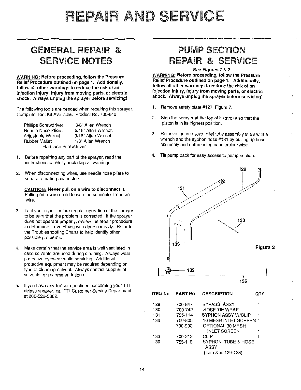
1.
Remove safety plate #127, Figure
2. Stop
3.
4. Tilt pump back for easy access to pump section.
the
piston
Remove the pressure relief tube assembly #129
wrench
assembly
injury
sprayer at
is
in
its highest position.
and
the
syphon hose
and
unthreading counterclockwise.
& SERVICE
See Figures 7 & 2
follow
on
page 1. Additionally,
from moving parts,
the
top of its stroke
#131
the Pressure
risk
of
or
electric
7.
so
that the
by
pulling
129
an
up
with
hose
13~/
a
3. Test your repair before regular operation of
to
be
sure that the problem
does not operate properly, review
to
determine if everything
the
Troubleshooting Charts
possible problems.
Make
4.
5.
certain that
case solvents are used during cleaning. Always wear
protective eyewear while servicing. Additional
protective equipment may
type of cleaning solvent. Always contact supplier of
solvents
If
airless sprayer, call
at
for
you have
800-526-5362.
the
recommendations.
any
further questions concerning your
Til
is
corrected. If
the
was
done correctly. Refer to
to
help identify other
service area
be
Customer Service Department
is
required depending
the
repair procedure
well
ventilated
the
sprayer
sprayer
in
on
Til
//~
il(
133 I ·
!--132
ITEM No PART No DESCRIPTION
129
130
131
132
133
136
700-847
700-742
755-114
700-805
700-900
700·212
755-113
BYPASS ASSY
SYPHON ASSY W/CLIP 1
OPTIONAL
y
HOSE TIE
10
MESH
INLET SCREEN
CLIP 1
SYPHON, TUBE & HOSE 1
ASSY
(Item
WRAP
INLET SCREEN 1
30
Nos 129·133)
Figure 2
136
QTY
MESH
1
14
Page 3
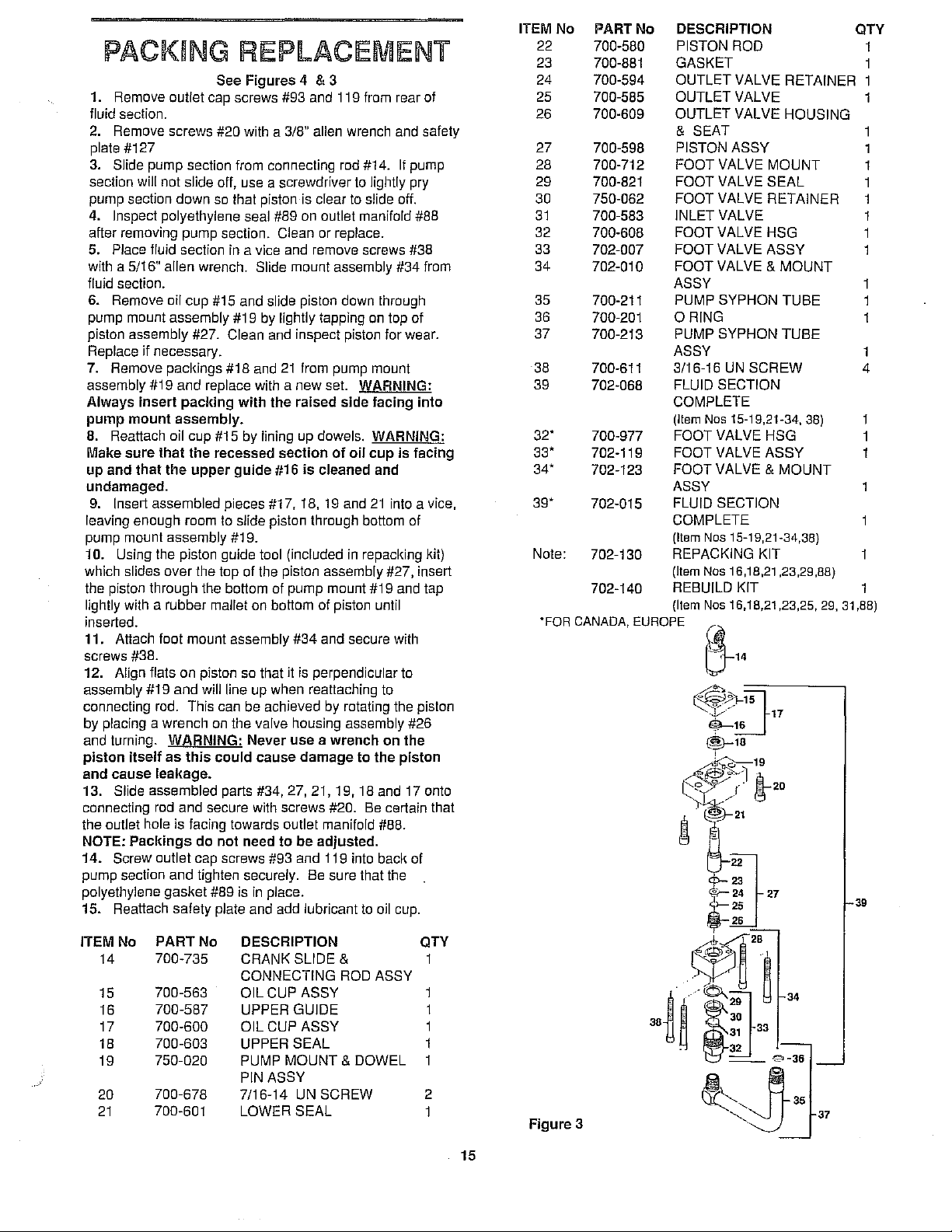
PACKING REPLACEMENT
See
Figures
1. Remove
fluid section.
2.
Remove screws #20 with a 3/8" allen wrench and safety
plate #127
3.
Slide pump section from connecting rod #14. If pump
section
pump section
outlet cap screws #93 and 119 from rear of
will
not
slide off, use a screwdriver to lightly pry
down
so that piston is clear to slide off.
4. Inspect polyethylene seal #89 on outlet manifold #88
after removing pump section.
5. Place
with a 5/16" allen wrench. Slide
fluid section.
6. Remove
pump mount
piston
Replace
fluid
section
oil cup #15 and slide piston down through
assembly #19 by lightly tapping on top of
assembly #27. Clean and inspect piston for wear.
if
necessary.
in
a vice and remove screws
7. Remove pacl<ings #18 and
assembly
Always
pump
8. Reattach oil cup #15 by lining up dowels.
Make
up
undamaged.
9.
leaving enough room to slide piston through bottom of
pump mount
10. Using the piston guide tool (included
which
the piston through the bottom of pump mount #19 and tap
lightly with a rubber mallet on bottom of piston until
inserted.
11. Attach foot mount
screws
12. Align flats on piston so that it is perpendicular to
assembly
connecting rod. This can be achieved by rotating the piston
placing a wrench on the valve housing assembly #26
by
and turning.
piston
and
13. Slide assembled parts #34, 27, 21, 19, 18 and 17 onto
connecting rod
the
NOTE:
14.
pump section
polyethylene
15.
1119
and
replace with a
insert
pacl<ing
mount
sure
and
Insert assembled pieces #17, 18, 19 and
slides
cause
outlet hole is facing towards outlet manifold #88.
Screw outlet cap screws #93 and 119 into
Reattach
assembly.
that
that
the
assembly #19.
over
1138.
1119
and
WARNING:
itself
as
leakage.
and
Pacl<ings
and
gasket
safety
the
this
with
recessed
upper
guide
the top of the piston assembly #27, insert
assembly
will line up when reattaching to
Never
could
secure with screws #20. Be certain that
do
not
need
tighten securely. Be sure that the
#89 is
in
plate and add lubricant to oil cup.
4 & 3
Clean or replace.
mount
21
from pump mount
new
set.
the
raised
section
1116
is
cleaned
1134
and secure with
use a wrench
cause
damage
to
be
adjusted.
place.
#38
assembly #34 from
WARNING:
side
facing
into
WARNING:
of
oif
cup
is
facing
and
21
into a vice,
in
repacking kit)
on
the
to
the
piston
bacl<
of
ITEM
No
PART
No
DESCRIPTION
22 700-580 PISTON ROD
23
24
25
26
27
28
29 700-821 FOOT VALVE
30
31
32
33
34
35
36
37
38
39
32"
33'
34"
39'
Note:
"FOR
700·881
700·594
700-585 OUTLET
700-609
700-598
700-712
750-062
700-583 INLET VALVE
700-608 FOOT VALVE
702-007
702-010
700-211 PUMP SYPHON
700-201
700-213
700-611 3/16-16 UN
702-068 FLUID
700-977 FOOT VALVE
702-119 FOOT VALVE
702-123 FOOT
702-015
702-130
702-140
CANADA,
GASKET
OUTLET
OUTLET
&
PISTONASSY
FOOT
FOOT
FOOT
FOOT
ASSY
ORING
PUMP
ASSY
COMPLETE
(Item
ASSY
FLUID SECTION
COMPLETE
(Item
REPACKING KIT
(Item
REBUILD KIT
(Item
EUROPE
SEAT
VALVE
VALVE
VALVE
VALVE &
SYPHON
SECTION
Nos
VALVE &
Nos
Nos
Nos
~14
VALVE RETAINER 1
VALVE
VALVE
15-19,21·34, 38)
15-19,21·34,38)
16,18,21 ,23,29,88)
16,18,21 ,23,25, 29.
HOUSING
MOUNT
SEAL
RETAINER
HSG
ASSY
MOUNT
TUBE
TUBE
SCREW
HSG
ASSY
MOUNT
31
QTY
1
1
1
1
1
1
1
1
1
1
1
1
4
,88)
39
ITEM
14
15
16
17
18
19
20
21
PART
No
No
700-735
700-563
700-587
700-600
700-603
750-020
700-678
700-601 LOWER
DESCRIPTION
CRANK
CONNECTING
OIL
UPPER
OIL
UPPER
PUMP
PIN
7/16-14 UN
SLIDE
CUP
ASSY
GUIDE
CUPASSY
SEAL
MOUNT & DOWEL
ASSY
SCREW
SEAL
QTY
& 1
ROD
ASSY
1
1
1
1
2
1
15
Figure
3
Page 4

SERVICE I REPLACEMENT
OF CLUTCH ASSEMBLY
See Figure 4
WARNING: Before proceeding, follow the Pressure
Relief Procedure outlined on page 1. Additionally,
follow all other warnings to reduce the
injection injury, injury from moving parts, or electric
shoe!<.
Removal of Clutch Plate Assembly
Always unplug the sprayer before servicing!
1. Remove engine/motor assembly #81 by removing allen
screws
#54.
2. Slide fan assy #73 and clutch plate #72 from engine.
3. Inspect clutch plate #72 and clutch rotor assy
wear. Replace if necessary.
Removal of Clutch Rotor Assembly
Follow steps 1-3 and remove rear mounting bolts #92
4.
and 93 from rear of fluid section.
5. Remove front cover #41 and (4) socket head screws
#42
located
in
pump housing assy #43.
6. Slide entire pump housing assy #43 from motor housing
assy #53.
Remove crank shaft
7.
from motor housing assy.
#45
and output pinion assy #48
8. Remove snap ring #51 from clutch rotor assy #67 and
slide rotor assy
Removal of Clutch Coil Assembly
#67
from housing assy #53.
9. Follow steps 1-8 and remove switch cover plate #60.
Disconnect wires from clutch starter #58
1 0.
clutch starter.
11.
Remove (4) screws #51 from coil assy #65 and slide
assy from motor assy #53.
12. To reassemble, reverse the procedures described
above.
ITEM No
40 700-653
41
42
43 750-008
44
45
46
47
48
49
50
51
52 750-015
53
PART
No
DESCRIPTION
SCREW 10
700-562
COVER
700-681 SCREW
PUMP HSG ASSY 1
700-680
730-360
730-088
700-688
THRUST WASHER
CRANK SHAFT
THRUST WASHER
THRUST WASHER
730-167 OUTPUT PINION ASSY
700-514
730-144
750-016
755-115
THRUST WASHER 1
SNAP RING 1
SNAP RING 1
BALL BEARING 1
MOTOR HSG ASSY 1
54 730-148 SCREW 4
56 710-127
57
58
59
60
61
730-145
730-060
730-146
710-147
700-748 SWITCH
SETSCREW
SCREW 2
CLUTCH STARTER 1
5 AMP FUSE 1
SWITCH COVER PLATE 1
TO
WIRE
risl<
of an
#67
for
as
indicated on
QTY
STARTER 1
1
4
1
1
1
1
1
1
ITEM No PART No DESCRIPTION
62 700-646
63 700-775
64
700-645 RUBBER BOOT
65 730-149
TOGGLE SWITCH
ON/OFF PLATE
COILASSY
66 730-150 SCREW
67 730-152 CLUTCH ROTOR ASSY
68 730-151 ELECTRICAL CONNECTOR
69 730-155 THRUST WASHER
70
71
72
730-154 THRUST BEARING
730-153
THRUST WASHER
RETAINER
730-140 CLUTCH PLATE ASSY
73 730-157 CLUTCH FAN ASSY
74
75
730-184
ELECTRICAL CONNECTOR
750-051 SCREW
76 750-086 ENGINE MOUNT
(Incl. 78,79)
77
78
750-018 SCREW
750-043 ENGINE OIL SEAL
79 750-044 ENGINE BEARING
80 750-042 GASKET
81
82
83
755-117
ENGINEASSY
(Incl. 74-80)
710-069 PLUG
730-006 MAXI FILTER HSG
84 730-083 FILTER SPRING
85 730-067 FILTER CARTRIDGE
86
87
88
730-018 FILTER CORE
730-005
702-081
FILTER GASKET
FILTER
HSG
89 700-804 PUMP OUTLET GASKET
90
91
730-195 3/8" PLUG
490-006 1/4" NIPPLE
92 700-685 SOCKET HEAD SCREW
93
94
700-681 CAP HEAD SCREW
700-699 PRESSURE RELEASE
FITIING
95 755-135 CLIP
96 225-002 SCREW
97 700-537 GASKET
98
99
100
101
102
103
104 700-698
105
106 700-731
107
108
109
110
111
112
113
114 700-499
115
116
221-012
0-RING
222-012 0-RING
700-755
700-721
700-752
700-706
700-705
700-754
700-759
700-697
700-757
BY-PASS
0-RING
BY-PASS VALVE STEM
WASHER
SPRING
WASHER
BY-PASS VALVE
RETAINER
BY-PASS CAM BASE
DOWEL
BY-PASS VALVE HANDLE
BY-PASS VALVE ASSY
(Item Nos 97-109)
HSG
PIN
700-784 SCREW
700-771 ADJUSTMENT KNOB
710-049 PRESSURE CONTROL
0-RING
700-483
GASKET 1
730-172 CLUTCH SEAL
117 730-165 GROUND WIRE 1
OTY
1
1
1
1
4
1
2
1
1
1
1
1
1
6
1
2
1
1
2
1
1
1
1
1
1
1
1
1
2
1
1
1
2
1
1
1
1
1
1
2
1
1
1
1
2
1
1
1
1
16
Page 5

"'
43
110
17
ITEM No
118
119
121
122
125
126
127
PART No
730-158
730-234
702-082
730-261
730-223
700-841
700-791
DESCRIPTION
QTY
DIPSTICK
SCREW
FILTER BLOCK ASSY
(Excludes Item Nos 92,119, 93,89)
THRUST WASHER ASSY 1
(Item Nos 69,70,71,125)
THRUST WASHER
INSULATOR JACKET
SAFETY
PLATE
1
1
1
1
1
1
Page 6

SERVICE /REPLACEMENT
OF INLET
See Figure 3
1. Remove lower foot valve and mount assembly #34
removing screws
2. Place lower valve mount assembly
remove foot valve assembly
3. Remove valve retainer #30 and inlet valve #31. if
unable to remove, unscrew pump syphon tube assembly
#37
and poke valve and retainer free
housing assembly
hammer
4. Clean and inspect valve #31, reverse or replace if
showing wear or damage. Rubbing lightly
sandpaper can remove any dried paint.
5. Clean valve housing assembly #32, check for wear or
damage. Replace if necessary.
6. Reattach fool valve assembly #33 to #28 and secure
tightly with a wrench. Reattach syphon tube assembly
if
#38
#32, using screw #38. Tap screw with a
necessary.
with
VALVE
a 5/16" allen wrench.
#34
in
a vice and
#33 with a wrench.
Jrom
bottom of
on
fine
by
#96.
tighten securely with a wrench.
washers
lubricate with grease. Line up cam
#88.
handle
pin
#105 and 103 are properly
7. Install bypass cam
8.
Using dowel pin, line up stem
#1
09. Secure handle with dowel pin
9.
Important:
on
cam
#1
07.
If
handle
Mal<e
sure that both
in
place.
#1
07 over bypass retainer
#1
07 with filter block
#1
02 with hole
#1
08.
#1
09 rotates 360 degrees, check
#1
on
SERVICE/REPLACEMENT
OF FILTER
See Figure 5
WARNING: Before proceeding,
Relief Procedure
follow
all
other
injection injury,
shock. Always
The
pump
after each use.
and
outlined
warnings
injury
unplug
gun
filter
from
the
should
follow
on page 1.
to
reduce the risl<
moving
sprayer
parts
before
be cleaned
the
Pressure
Additionally,
of
an
or
electric
servicing!
or
reolaced
06,
SERVICE/REPLACEMENT
OF UPPER (OUTLET)
VALVE
See Figure 3
1. To clean or replace upper valve, remove valve housing
assembly
pump. This
2. Remove valve retainer
and inspect along with housing
worn or damaged. Use fine sandpaper to remove dried
paint.
3. Reattach assemblies #32, #25 and #26
and secure tightly wit, 1 a wrench.
#26 while piston assembly
will prevent the piston from rotating.
#24
#27
is still attached to
and outlet valve #25. Clean
#26. Reverse or replace if
to
piston #22
SERVICE/REPLACEMENT
PRESSURE RELIEF
PRIME VALVE
See Figure 5
WARNING:
Relief
follow
injection
shock.
Before
Procedure
all
other
warnings
injury,
Always
proceeding,
outlined
injury
unplug
on
to
from
the
follow
page
1.
reduce the
moving
sprayer
before
the
Pressure
Additionally,
risk
of
parts
or
electrical
servicing!
an
NOTE: If
blockfiller, remove
PUMP
1. Unscrew filter housing #83.
2.
3.
4.
GUN
WARNING:
in high pressure
your
release the
damaged
Replacement
1.
First pull down
away from handle.
2.
Unscrew handle
3.
Unscrew filter
(NOTE: Left handed thread, turn the filter clockwise to
remove.)
4.
Screw new or cleaned filler into the head. (Turn counter
clocl<wise.)
5.
Reattach handle to head and secure safety trigger
guard.
wood
spraying
Fll
Remove filter cartridge #85. Clean or replace.
Inspect seal #87. Clean or replace.
Reattach filter housing #83. Secure with a wrench.
Fll
Follow
spray
gun
trigger,
or
dirty
(NOTE: if filter
screw
to
heavy-bodied materials
all
filters
from
TEFI
TER
or
remove.)
--See
Figure 5
--
all safety precautions as
warning
leaks
and
Removal
on
Jrom
from
section before proceeding.
or
spits
at
the
the
needle
must
trigger safety guard and swing
spray head.
breal<s
or
be
replaced
of
Filter:
spray head.
off
in
such
system.
described
tip
when
you
seat
is
worn
or
or
cleaned.
the head, use a small
-~
as
If
1. Remove dowel
#109. Push out pin as shown
2.
Remove handle
3.
Using a wrench, loosen bypass housing
unscrew.
bypass valve stem #1 02.
5.
bypass housing
Inspect D-Ring
6.
assembly into filter block except
Inspect
4.
Unscrew bypass valve retainer
Inspect ball on
When reinstalling, screw completely assembled
0-Rings
#1
00.
#1
01.
pin
#1
08 from bypass valve handle
in
Figure 5.
#1
09 and bypass cam #107.
#99 and 98.
#1
06 and remove
end
of
stem
#1
02 and seat, located
Clean or replace, if damaged.
#107, 109 and 108 and
#1
DO
and
in
18
Page 7

ITEM No PART No
PTFE
82 710-069
83
84
85 730-067
86
87
88
89 700-804
90
91
92 700-685
93 700-681
94
97 700-537
98
99 222-012
100
1
01"
102
103
104
105
106
107
108
109
11
0
113 761-140
114
115
119
121
730-006
730-083
730-018
730-005
702-081
730-195
490-006
700-699
221-012
700-755
700-721
700-752
700-706
700-698
700-705
700-731
700-754
700-759
700-697
700-757
700-499
700-483
730-234
702-082
700-897
700-890
DESCRIPTION QTY
PLUG 2
MAXI FILTER
FILTER SPRING 1
FILTER CARTRIDGE 1
FILTER CORE
GASKET
FILTER
PUMP OUTLET GASKET
3/8" PLUG
1/4" NIPPLE
1/4-20
UN
1/4-20
UN
PRESSURE RELEASE
FITIING
GASKET
0-RING
0-RING
BY-PASS
#005 0-RING
BY-PASS VALVE SYSTEM
WASHER
SPRING
WASHER
BY-PASS VALVE 1
RETAINER
BY-PASS
DOWEL
BY-PASS VALVE HANDLE
BY-PASS VALVE ASSY
PRESSURE CONTROL
0-RING
GASKET
1/4-20 UN SCREW
FILTER HSG ASSY
(Excludes
OPTIONAL TEFLON 1
0-RING
BY-PASS 0-RING TOOL
HSG
HSG
SCREW 2
SCREW 1
HSG
CAM BASE
PIN
llem
Nos
89,92,
93,11
2
9)
1
1
1
'
1
1
1
1
l_j
I
o'=---
L j b
-82
-83
,
-as
121
--88
0--89
110
I
I
91
! I
/
92
Figure 5 ,
19
Page 8

PRESSURE SWiTCH
REPLACEMENT
See Figure 6
WARNING: Before proceeding, follow the Pressure
Relief Procedure outlined on page 1. Additionally,
follow
all other warnings to reduce the risk of
injection injury, injury from moving parts or electric
shock. Always unplug the sprayer before servicing!
1. Remove head cap screws #93 and 119 from rear of fluid
section and bottom of filter block.
2.
Remove filter block #87.
3.
Remove switch cover plate #60, located near pressure
switch and disconnect two red wires from clutch starter #58.
4.
Remove screw
knob and slide knob off.
5.
Remove screw
housing #53 and using a
screw #56, until pressure switch
through. Feed electrical wires down at the same time.
6.
Insert new switch assembly #113 into housing while
carefully working the wires into the switch box. Using
needle
nose
7. Making sure that
tighten set screw #56 with a
switch assembly is secure. Reattach adjustment knob
#112.
B.
Inspect
properly
dowels.
sure that the pump outlet gasket #89 is properly
before installing filter block #88.
9.
Install switch plate #60.
10.
adjustment is required.
0-Rings
in
place, then install filter block #88 by lining up
Secure with screws #93 and 119. Note: Make
The pressure switch is factory calibrated so
#111
from pressure switch adjustment
#111
located
pliers,
reconnect
the
switch assembly is fully inserted,
#114 and 115 on switch assembly. If
on
side of gear box
1/8"'
allen wrench remove set
#113 is able to slide down
wires
to
motor
1/8'"
allen wrench until the
an
starter.
in
no
place
"'
ITEM No
53
54
56
57
58 730-060
59
60
61
62
63
64
82
83
84
85
86
87
PART
755-115
730-148
710-127
730-145
730-146
710-147
700-748
700-646
700-775
700-645
710-069
730-006 MAXI FIL TEA HSG
730-083
730-067
730-018 FILTER CORE
730-005
DESCRIPTION
No
MOTOR HSG ASSY
SCREW
SETSCREW
SCREW
CLUTCH STARTER
5 AMP FUSE
SWITCH COVER
SWITCH TO STARTER 1
WIRE
TOGGLE SWITCH 1
ON/OFF
RUBBER BOOT
PLUG
FILTER SPRING
FILTER CARTRIDGE
FILTER GASKET
PLATE 1
PLATE 1
1
2
1
1
1
1
1
QTV
1
4
1
2
1
1
20
Figure 6
PART
No
ITEM No
88
89
90
9t
92
93
94 700·699 PRESSURE RELEASE
111
112
113 761-140
114
115 700-483
119
121
126
702-081 FILTER HSG
700·804 PUMP OUTLET
730-195
490-006
700·685 SOCKET HEAD SCREW 2
700-681 CAP HEAD SCREW
700·784 SCREW
700-771 ADJUSTMENT KNOB 1
700·499
730·234 SCREW
702·082 FILTER BLOCK ASSY 1
(Excludes
700·841 INSULATOR JACKET 1
DESCRIPTION
GASKET
3/8'"
PLUG
1/4'"
NIPPLE
FITIING
PRESSURE CONTROL 1
0-RING
GASKET
Item
Nos
89,92,93,119)
QTY
2
2
1
1
1
Page 9

GEAR REPLACEMENT
See Figure 7
WARNING: Before proceeding,
Relief Procedure
follow
all
other
injury,
injury
Always
unplug
outlined
warnings
from
moving
the
sprayer
on
to
reduce
parts,
before
follow
page 1.
or
servicing!
the Pressure
Additionally,
risk
electric
of
an
injection
shock.
1. Remove safety plate
2. Remove front cover #41.
3. Remove mounting bolts #93 and 119, from rear of pump.
4.
Remove
housing
5.
Inspect gears beginning with crank shaft assembly #45.
Then output pinion gear #48.
6. Reassemble
reassembling, make sure that
that gears and bearings are
(4)
socket head screws #42 and slide pump
assembly #43 from gear box housing #53.
by
11127,
from front of pump.
reversing the above order. When
all washers are
properly lubricated.
in
place and
111
r
W®r"2
! 53
~~~·
6
/~
6,]
54
46
43
40
ITEM No PART
40 700-653
41
42 700-681
43
44
45
46
47 700-688
48
49
50
51
52 750-015 BALL BEARING 1
53 755-115
54
No
DESCRIPTION
SCREW 10 56
700-562
750-008
700-680
730-360 CRANK
730-088
730-167
700-514
730-144
750-016
730-148
COVER
SCREW 4
PUMP HSG ASSY
THRUST WASHER
THRUST WASHER
THRUST WASHER 1
OUTPUT PINION ASSY
THRUST WASHER 1
SNAP RING 1
SNAP RING
MOTOR HSG ASSY
SCREW
SHAFT
QTY ITEM No
1
1 59
1
1
1
1
1 96
1 112
4 127
21
57
58
60
61
62
63
64
95
111
.
.
'8".
-~~
Figure
PART No DESCRIPTION
710-127
730-145
730-060 CLUTCH
730-146
710-147
700-748
700-646
700-775
700-645
755-135
225-002
700-784
700-771
700-791
SETSCREW
SCREW
5
AMP FUSE
SWITCH COVER PLATE
SWITCH TO STARTER 1
WIRE
TOGGLE SWITCH
ON/OFF PLATE
RUBBER
CLIP
SCREW
SCREW
ADJUSTMENT
SAFETY PLATE
·-,
·-,
7
STARTER
BOOT
·-,/
-~-
·-......
QTY
1
2
1
1
1
1
1
1
1
2
2
KNOB
1
1
127
.......
 Loading...