

Page 1
Pre-Assembled Under Sink Pump Package
Operating & Installation Instructions
This assembly has been carefully packaged, inspected and tested to ensure safe operation and delivery. Before installing the pump package,
check to see if any damage has occurred to the package from rough handling. Notify the dealer from whom you purchased the pump package if
any damage has occurred.
This package has been designed to pump reasonably clean water. DO NOT PUMP chemicals, corrosive liquids, oils, sewage or effluents. Please
read all instructions before installing this package. Operating this product outside the design limits or failure to comply with these instructions will
void the warranty.
Safety Instructions
The following safety rules should be followed to avoid serious injury or property damage:
Always remove the plug from the electrical outlet before servicing this pump.
1. Check the local electrical and plumbing codes to ensure you comply with the regulations. These
codes have been designed with your safety in mind. Be sure to comply with them.
2. We recommend that a separate circuit be led from the home electrical distribution panel and
properly protected with a fuse or a circuit breaker. We also recommend that a ground fault circuit
interrupter be used. Consult a licensed electrician for all wiring
.
3. Do not stand in water when connecting or disconnecting power cord from outlet.
4. This product should be connected to a three prong grounded outlet equipped with a ground fault
circuit interrupter (GFCI).
5. Do not pump flammable liquids with this pump package as an explosion or fire could result.
6. This product does not require lubrication. A special oil has been put into the motor housing at the
factory for lifetime lubrication of the bearings. Use of any other oil can cause damage and void
the warranty.
Pump Operation
The pump will start when the water has filled the tank to a depth that engages the automatic float switch. The pump will not stop until the water
depth disengages the automatic float switch. The pump will recycle thereafter as required. Allow the pump to go through several cycles to assure
satisfactory operation. If the pump does not operate properly, see Trouble Shooting Checklist.
1
#54463EF 9/08
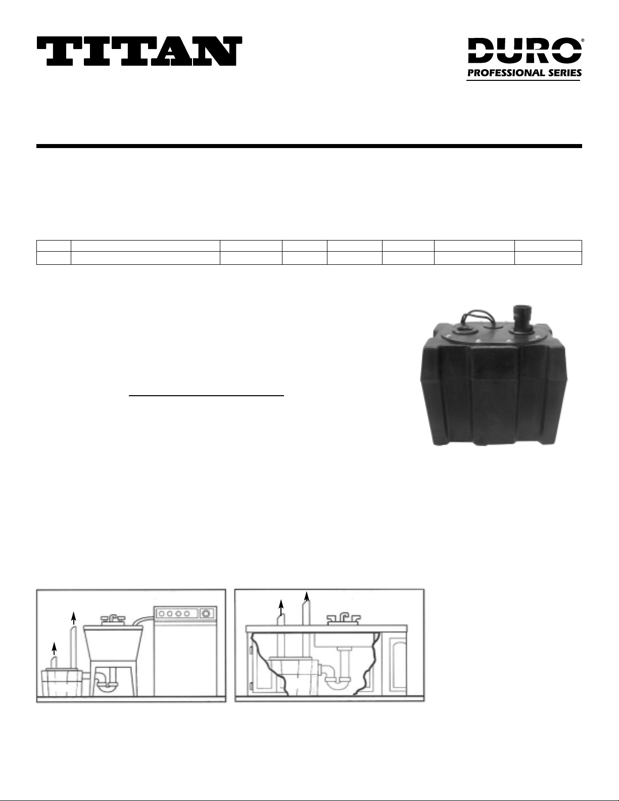
Installation
Figure 1 - Typical Residential Installation
PUMP
VENT
VENT
DISCHARGE
DISCHARGE
PUMP
Item No. Description Pump Model* Switch Type Inlet Discharge Dimensions W x D x H Shipping Wgt (lbs)
8101 Premium Under Sink Pump Package DSB250VP DSB250V (1/3 hp) Vertical 1-1/2" Female 1-1/2" Female 17.5" x 12" x 14" 19.5
*Refer to Pump Specifications on page 2.
Page 2
2
Electrical Information
WARNING: Risk of electrical shock - this pump is supplied with a 3-prong grounded plug. To reduce the risk of electrical shock, be
certain that it is connected only to a properly grounded receptacle.
WARNING: ALTERATIONS OF THE POWER CORD VOIDS THE WARRANTY.
The pump package operates on a 115 volt, 60 cycle AC, single phase and has three-prong electric plug. The third prong is used to ground the
pump to prevent possible fatal shocks. The third prong must not be removed. The fuse or circuit breaker used should be a 15 amp time-delay type.
Automatic Thermal Overload Protection
The motor has a built-in automatic overload protector. It will cut off the power to the motor before the temperature rises enough to damage the
motor windings. Should the overload stop the pump operation, it will reset automatically. Operation will resume when the motor cools enough to
close the overload switch.
Maintenance Instructions
THIS PRODUCT HAS BEEN DESIGNED TO DRAIN WATER FROM THE UNDERSINK TANKS TO AVOID FLOODING IN THE HOME. THE
APPLICATION OF THIS PRODUCT IS FOR PERMANENT INSTALLATION. DO NOT USE THIS PUMP PACKAGE TO PUMP LIQUIDS (WATER)
IN EXCESS OF 100°F.
Servicing And Cleaning
Refer to Trouble Shooting Checklist if pump does not operate properly. Figure 3 shows the diagram of disassembly of this package.
Figure 4 is a schematic diagram of disassembly of the base from the pump housing for cleaning purposes. The following steps are for service and
cleaning of the pump, tank and pump:
1. Make sure the power cord is disconnected before any servicing is performed.
2. Remove the screws of the lid and lift the pump.
3. Remove the screws from the bottom pump base plate, as shown in Figure 4. Clean all trash and debris away from the inlet pump volute.
4. Check to see if the impeller spins freely inside the volute.
5. When re-assembling be sure not to overtighten screws.
Installation Cont'd
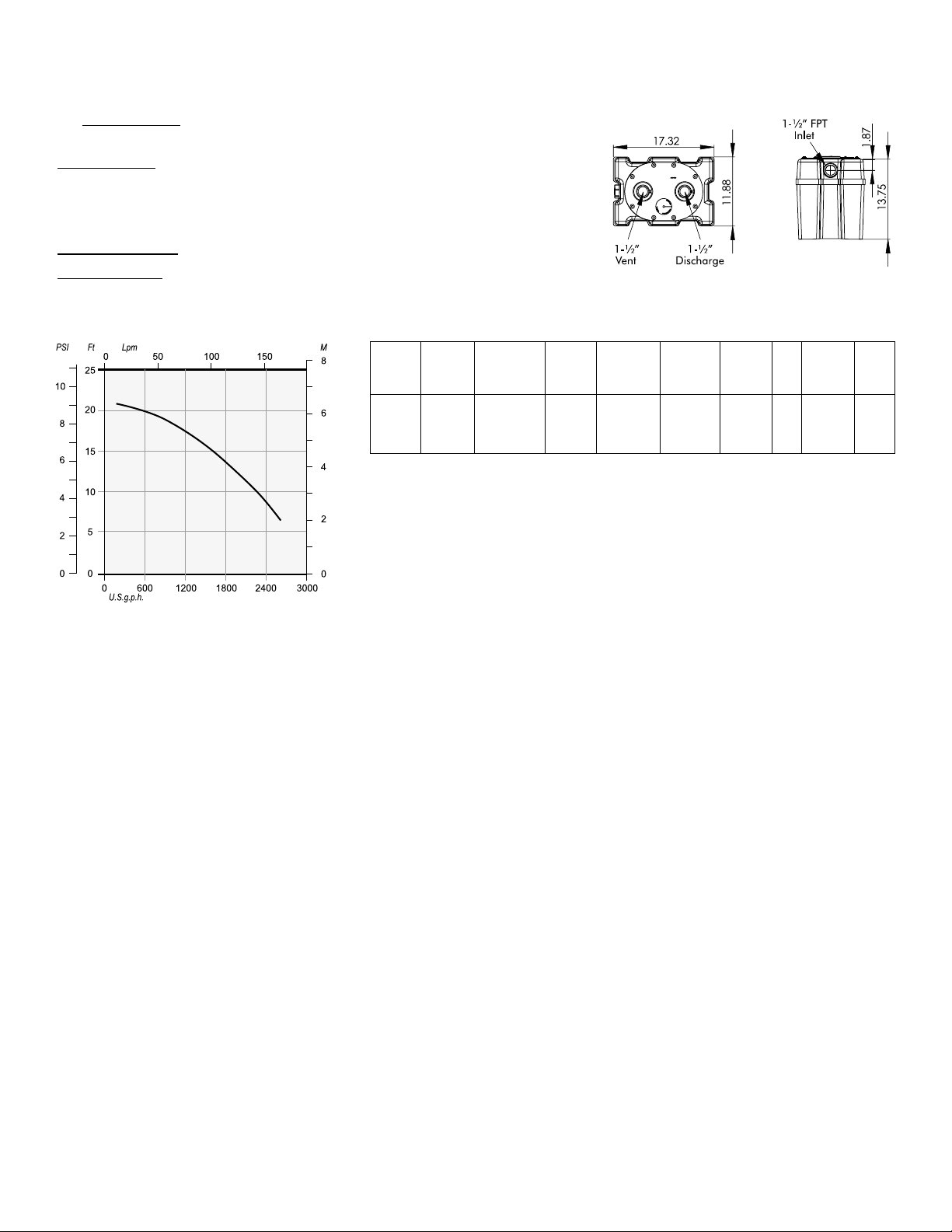
Performance Curve (Pump)
Pump Specifications
This curve normally reflects the optimized performance of the pump.
Max. Max. Max.
Item Model Switch Discharge Capacity Voltage Hz Current RPM
Number Number Description Type Head (ft) (USGPH) (Amp.)
8094 DSB250V Submersible Vertical 23 3200 115 60 3.67 3450
Sump Pump
1/3HP
Figure 2 - Installation Dimensions
The inlet port (1-1/2” (38 mm) FPT) is located at the side of the tank. Use appropriate piping
and hand tighten only
.
The discharge pipe is attached to a 1-1/2” (38 mm) FPT adapter. Use appropriate piping and
hand tighten only.
The vent has been provided to allow extra volume for high lather conditions. Attach 1-1/2” (38
mm) pipe for venting purposes. The venting methods must comply with local and national
codes.
Automatic Operation: The two power cords should be connected together.
Manual Operation:
In an event of float switch failure, the pump cord can be separated from
the switch cord and hence bypassing the switch. Make sure that the pump does not run dry.
DSB250 (V)
Page 3

3
Figure 4 - Parts Breakdown (Pump)
Item #
Description
1 302718 Pump Volute
2 302719 O Ring
3 302720 Impeller (8091 & 8092-70.00 MM)
302721 Impeller (8093 & 8094-74.0 MM)
302722 Impeller (8095 & 8097-78.0 MM)
4 302723 Pump Base
5 302724 Hose Adapter
(1-1/2” MNPT x 1-1/4” FNPT)
6 302725 Mechanical Seal
7 — Motor Body & Stator
8 302726 Lip Seal
9 — Bearing
10 — Rotor
11 — Bearing Housing
12 — Pump Gasket
13 — Capacitor
14 — Upper Casing
15 — Cord Clamp
16 — Air Block
17 — Barrel Connector & Plug
18 — Screw
19 302727 Tether Float Switch
20 — Vertical Float Switch
Figure 3 - Parts Breakdown (Pump Package)
Page 4

GUARANTEE
This pump product is guaranteed to do the work for which it is intended when properly installed and operated. It is
warranted to be free of defects in material and workmanship for a period of two years from date of manufacture. The
only exception shall be when proof of purchase or installation is provided and then the warranty period shall be from
the date thereof.
How To Claim Warranty
The dealer from whom you purchased your unit has a thorough knowledge of its operation and maintenance. If
trouble develops, please consult the dealer.
If a unit or part should prove defective within 24 months, return it to your dealer, transportation charges prepaid. The
repair will be made or a replacement unit or part will be supplied free of charge. The serial number of the unit, or unit
from which the defective part is taken, must be supplied.
This warranty does not obligate the manufacturer to bear the cost of field labor or transportation in connection with the
replacement or repair of defective parts or units, nor shall it apply to any product upon which repairs or alterations
have been made, unless authorized by the manufacturer.
The manufacturer shall in no event be liable for consequential damages or contingent liabilities arising out of the
failure of any product, its power unit or its accessories to operate properly. No express, implied or statutory warranty
other than herein set forth is made authorized to be made by the manufacturer.
Trouble Shooting Checklist
1. Pump does not run or hums
• Tripped breaker, blown or loose fuse or other interruption of power
• Water level too low for float switch to operate
• Float may be stuck - it should operate freely in basin
• Power cord not making contact at pump - tighten locking nut on pump
• Power cord not making contact in wall receptacle
• Thermal protector switch opened - allow pump to cool
• Return for service
2. Pump runs or hums but does not pump or delivers insufficient
capacity
• Pump not properly sized for application
• Incorrect voltage
• Discharge restricted
• Shut-off valve closed
• Impeller jammed or inlet screen plugged with trash or debris
• Pump may be air locked - start and stop pump several times
• Return for service
3. Pump will not turn off
• Float switch stuck in the up position - make sure it is free in basin
• Excessive inflow or pump not properly sized for application
• Return for service
4. Fuse blows or circuit breaker trips when pump starts
• Fuse size or circuit breaker may be too small - need 15 amps
• Impeller jammed or rubbing on trash and debris
• Return for service
5. Pump cycles too frequent
• Check valve not installed or leaking
• Return for service
6. Water or soap suds come out of vent pipe
• Vent pipe is too short or too small in diameter
• Rate of inflow exceeds pump output
WATERGROUP INC. WATERGROUP COMPANIES INC.
FRIDLEY, MN REGINA, SK • CAMBRIDGE, ON
1-800-354-7867 1-877-288-9888
www.watergroup.com
 Loading...