

Page 1

TITAN DK 2500
English
OPERATOR'S MANUAL
NV. A. DE KONINCK
Avenue Sleeckx 84-86
B-1030 BRUSSELS -BELGIUM
Phone : ++32/2 216 31 40 Fax : ++32/2 242 41 89
E-mail : info@titansew.com Web : www.titansew.com
Page 2

DK 2500 MANUAL E PAGE 1
Chapter 1: Installation and lubrication
1. INSTALLATION ................................................................................................................................3
a. Complete machine - with motor and table.................................................................................3
b. Sewing head only .......................................................................................................................5
2. LUBRICATING THE SEWING HEAD....................................................................................................5
Chapter 2: Threading
1. TYPES OF YARNS.............................................................................................................................7
a. Needle yarn................................................................................................................................7
b. Chain yarn .................................................................................................................................7
HREADING ....................................................................................................................................7
2. T
a. Needle thread.............................................................................................................................7
b. Chain yarn .................................................................................................................................7
Chapter 3: Stitch formation
1. CHAIN YARN FEED ..........................................................................................................................9
2. Stitch density setting......................................................................................................................11
a. On standard equipment............................................................................................................
b With the stitch density regulator...............................................................................................11
Chapter 4: Mechanic adjustment of the sewing head
1. TYPES OF NEEDLES .......................................................................................................................13
a. How often are the needles to be replaced?..............................................................................13
b. Needle replacement..................................................................................................................13
c Needle height adjustment..........................................................................................................15
d. Replacing the needle bar and adjusting the needle height ......................................................15
2. UPPER LOOPER..............................................................................................................................17
a. Preparatory work.....................................................................................................................17
b. Replacing the upper looper .....................................................................................................17
11
c. Upper looper fine adjustment...................................................................................................17
3. THE LOWER LOOPER .....................................................................................................................19
a. Preparatory work.....................................................................................................................19
b. Replacing the lower looper......................................................................................................19
c. Adjusting the upper looper to the lower looper .......................................................................21
d. Adjusting the distance between needle and lower looper........................................................21
4. THE CUTTING MOTION...................................................................................................................23
a. Renewing the upper knife.........................................................................................................23
b. Renewing the lower knife.........................................................................................................23
c. Knife fine adjustment ...............................................................................................................23
d. Aligning the lower blade with the needle plate........................................................................23
5. THE PRESSER FOOT ................................................................................................................. 23-25
6. FEED-DOG.....................................................................................................................................26
7. CHAIN GUIDE ................................................................................................................................27
8. STITCH PLATE FINGER ...................................................................................................................27
Chapter 5: Maintenance schedule
Maintenance schedule........................................................................................................28
Page 3
TIT
DK 2500 MANUAL E PAGE 2
AN
DK2500
ADD
OIL
YARN
OIL
HERE
LEVEL
STAND
2587012P
i------------------------------.
I
@a,...___
25841E
25841VSC
·-........_
25882
2
5884
........._
25882V
........._
I
vsET
LOOPER
FIG
25884
YARN
1.1
25841R
I
I
T 16/12/04
Page 4
DK 2500 MANUAL E PAGE 3
Chapter 1: Installation and lubrication
1. Installation
a. Complete machine - with motor and table
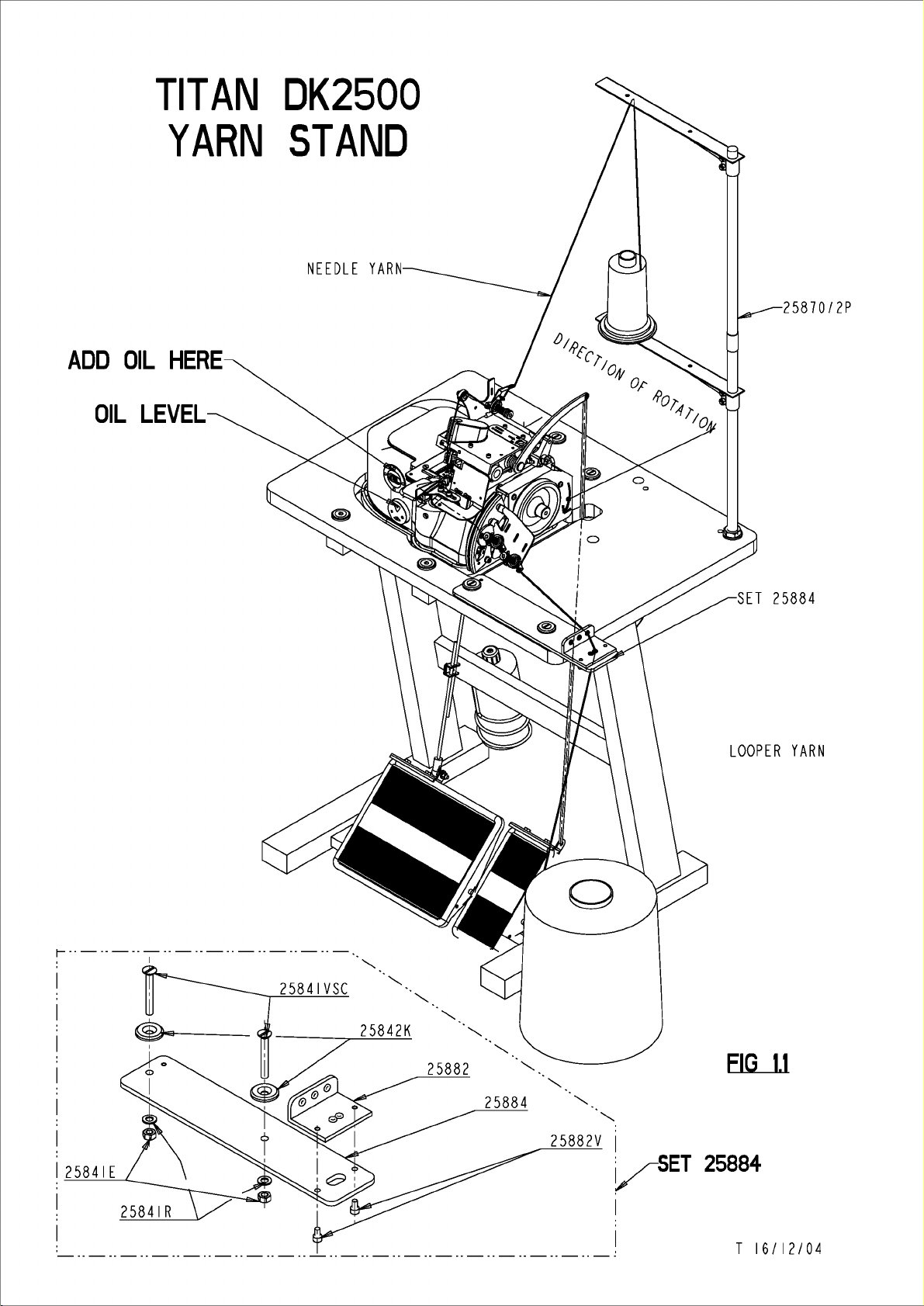
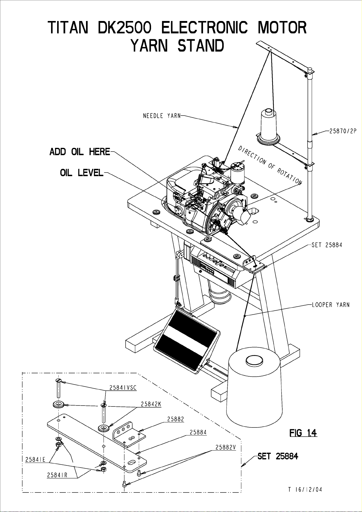
For units, supplied complete with motor and table, use FIG 1.1+1.4
1. Mount the yarn-stand 25850/2P en screw it on the table.
2. Mount the yarn guide plate SET 25884 on the table.
3. Place the black rubber anti-vibration blocks(25840) in the aluminium holders .
4. Take the TITAN DK 2500 machine out of its box. TAKE CARE NOT TO LIFT UP
the machine by holding the UPPER PARTS. Instead, place your hands
underneath the closing plate of the machine, and lift the machine. Place the 3
little feet attached at the lower plate, precisely in the black rubber blocks.
5. Look underneath the table, and loosen the nut of the motor, with a flat key of 24.
This allows the motor to rotate upwards or downwards .
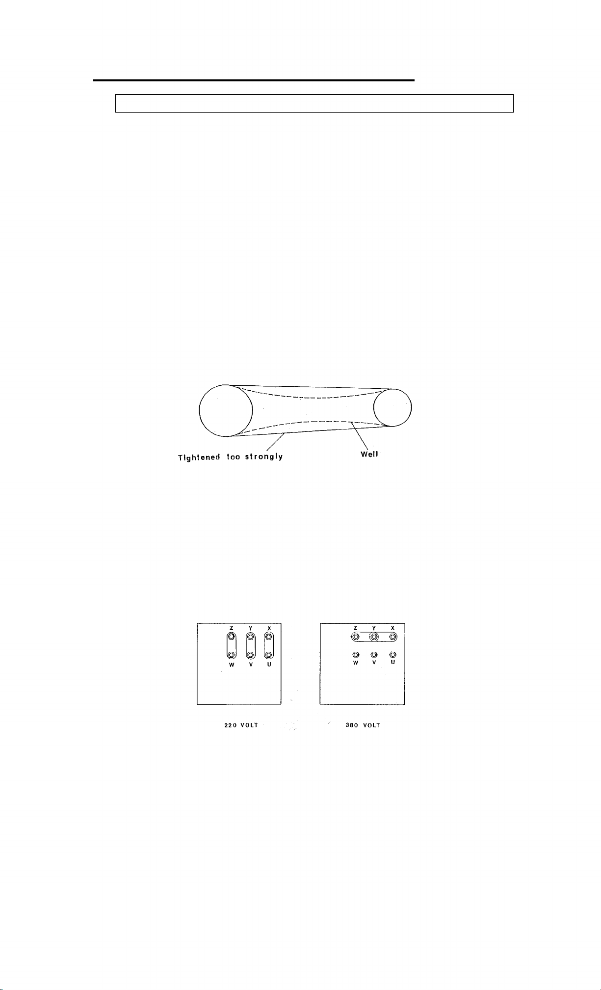
6. Push with one hand the motor upwards, and place the driving belt (attached to
the sewing machine) (M10012) around the pulley of the motor. Push the motor
down to stretch the belt slightly as seen in FIG 1.2.
-----------
--------
---
--
Tightened
7. Unscrew the cover marked “OIL” on the machine. Take the two oil bottles out of
the box and fill the machine with 1.5 L oil. Check if sufficient oil has been added
by looking at the oil-level glass. The oil level should be exactly between the two
red arrows. Close the cover again.
The electric motor is supplied, connected for use on 380V/3 PHASE supplies. For use
on 220V/3PH supplies, use the connection diagram (FIG 1.3). Connect the cores of
the mains to the receptacles of a plug designed for local operation (not included).
Verify that the direction of rotation is correct (FIG 1.1).
too
strongly
Z Y X
~ ~
bl
bl
V u
w
FIG 1.2
f@1
bl
Well
y
z
(~
~
@ @ @
V
w
X
~
u
220
FIG 1.3
VOLT
380
VOLT
Page 5
TIT
AN
DK25OO
ELECTRONIC
MOTOR
ADD
OIL
OIL
HERE
LEVEL
YARN
STAND
2587012P
i------------------------------.
I
25841VSC
·-........_
@a,...___
25882
25841E
25841R
2
5884
........._
25882V
........._
I
vsET
I
I
FIG
25884
T 16/12/04
1.4
Page 6
b.
Sewing head only
The sewing
motor rating¾
Use a pulley
Verify direction of rotation (FIG 1.1)
Prior
the machine.
See previous paragraph for more information about this.
I
2.
Lubricating the sewing head
Utilising splash lubrication, the sewing head
the components concerned.
machine with oil level lower
determination of
ATTENTION: the machine should NEVER RUN WITHOUT
The machine will loose daily a small amount of
is
recommended. If required, refill the oil reservoir
marking OIL just above the sight-glass.
Very important: oil type SP68.
The type of
SP68.
Recommended
to
starting
head
requires a drive motor that must meet the following specifications:
HP
and
rated
load
speed 2.800
80
mm
in
oil
diameter
the
sewing machine, always make sure
the
oil level (see
to
be
used
oil
types: CASTROL-ALPHA SP68 or any similar
to
match the V
is
To
get the maximum performance, never
than
the minimum level
FIG
1.1+1.4).
in
this sewing machine should
rpm.
belt.
to
pour about 1,5 I of
designed for optimum lubrication of
line.
The sight-glass allows quick
OIL.
oil.
An
inspection at periodical intervals
by
unscrewing the filler
be
of following viscosity:
oil
grade.
run
the
plug
oil
into
all
ATTENTION:
excessive wear, which
Conversely, use of high-viscosity oils
necessitate early renewal of the spare parts from lack of lubrication.
VERY IMPORTANT:
I.)
( 1.5
Remove the
bucket. Replace the
If
the oil
machine
Change the gasket (25839J)
refill the machine with oil as described above.
Use
of low-viscosity oils
in
turn will necessitate early renewal of the internal parts.
OIL
should
ONCE A MONTH. This is best done after a
plug
for oil draining underneath the machine
plug
and add
is
strongly polluted, it
and
to
remove
all
excess deposit, which has accumulated
will
result
in
poor lubrication properties
will
lead
to
lines clogging, which
be
completely removed
new oil (1.5
is
recommended
and
close the cover. Place the machine
I)
through the
to
remove
few
and
new oil should
hours
of
and
let the oil leak
plug
marked
the
cover underneath the
and
in
turn will
operation
OIL.
on
the cover.
on
the table
be
in
added
a
and
Page 7
TIT
DK 2500 MANUAL E PAGE 6
AN
DK2500
25900
THREADING
25900A
25900B
FIG
DIAGRAM
SEE
DETAIL
2.1
A
DETAIL
SCALE
A
2/5
T
07/01/2005
Page 8

DK 2500 MANUAL E PAGE 7
Chapter 2: Threading
1. Types of yarns
a. Needle yarn:
Many types of yarns can be used on the machine. Good results have been obtained
with following qualities : Nylon polyamide yarn of thickness 30 or 40,
Monofil (invisible) thread of 750 denier. (0,3 mm diameter) or
cotton (for example, mercerized cotton, thickness No.18).
b. Chain yarn (or “looper yarn”):
A wide range of threads can be used with DK 2500 machines.
Good results have been obtained with following qualities:
Polypropylene and Polyamide Nylon are most frequently used in thickness ranging
from 1800 detex till 5200 detex. The threads
gives better results after sewing, because the thread flattens out and covers the
carpet better.
Other qualities like wool, acrylic or cotton have also been used with success.
2. Threading
Remark: always switch off the motor prior to threading the yarns!
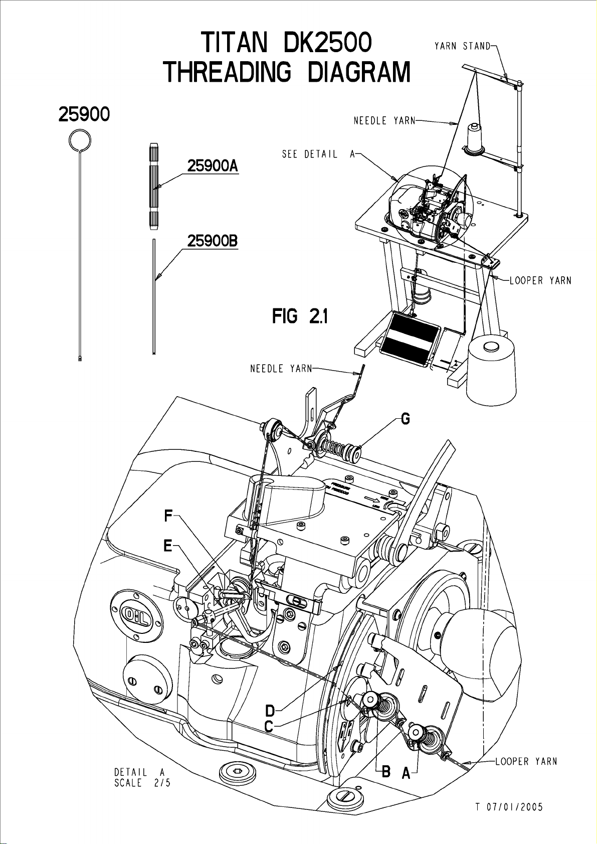
a. Needle thread
should be very lightly twined. This
Refer to FIG 2.1 THREADING DIAGRAM for the details.
b. Chain yarn
1. Turn the hand-wheel by hand and bring the take-up D in its topmost
2. Turn the hand-wheel by hand and bring the take-up D in its
3.
4. Tightly wrap the chain yarn around the point of the threading needle and push it
5. Gently remove the threading needle and push some more chain yarn into the
6. Turn the flying-wheel by hand to make sure the chain yarn extends above the
7. Make sure the needle thread remains threaded. The sewing machine is now
Note: For improved covering, use two or three thinner threads in the lower
looper.
position. Lead the yarn thru the tension-adjusters A and B and by hole C thru the
plates on both sides of the take-up D.
bottommost
position. In this position the eye of the lower looper faces the threading tube E
Thoroughly clean (if necessary, using the threading needle, part 25900) the
lower looper's eye.
all the way (as far as possible) into the threading tube and through the eye of the
lower looper
threading tube in order to obtain a small tangle of chain yarn behind the lower
looper's eye F
needle plate.
ready for use.
F.
EMARK: Remember : remove the THREADING NEEDLE ALWAYS.
. R
Page 9
TIT
DK 2500 MANUAL E PAGE 8
AN
DK25OO
STITCH
NEEDLE
CARPET
YARN
C:
A:
NOT
ADJUSTMENT
LOOPER
OK
OK
YARN
FIG
3.1
LOOPER
B:
NOT
D.
NOT
YARN
OK
OK
D
H
FIG
IMITATION
3.2
FIG
3-THREADSTITCH
3.4
C
FIG
J
3.3
T
25/11/04
Page 10

DK 2500 MANUAL E PAGE 9
Chapter 3: Stitch formation
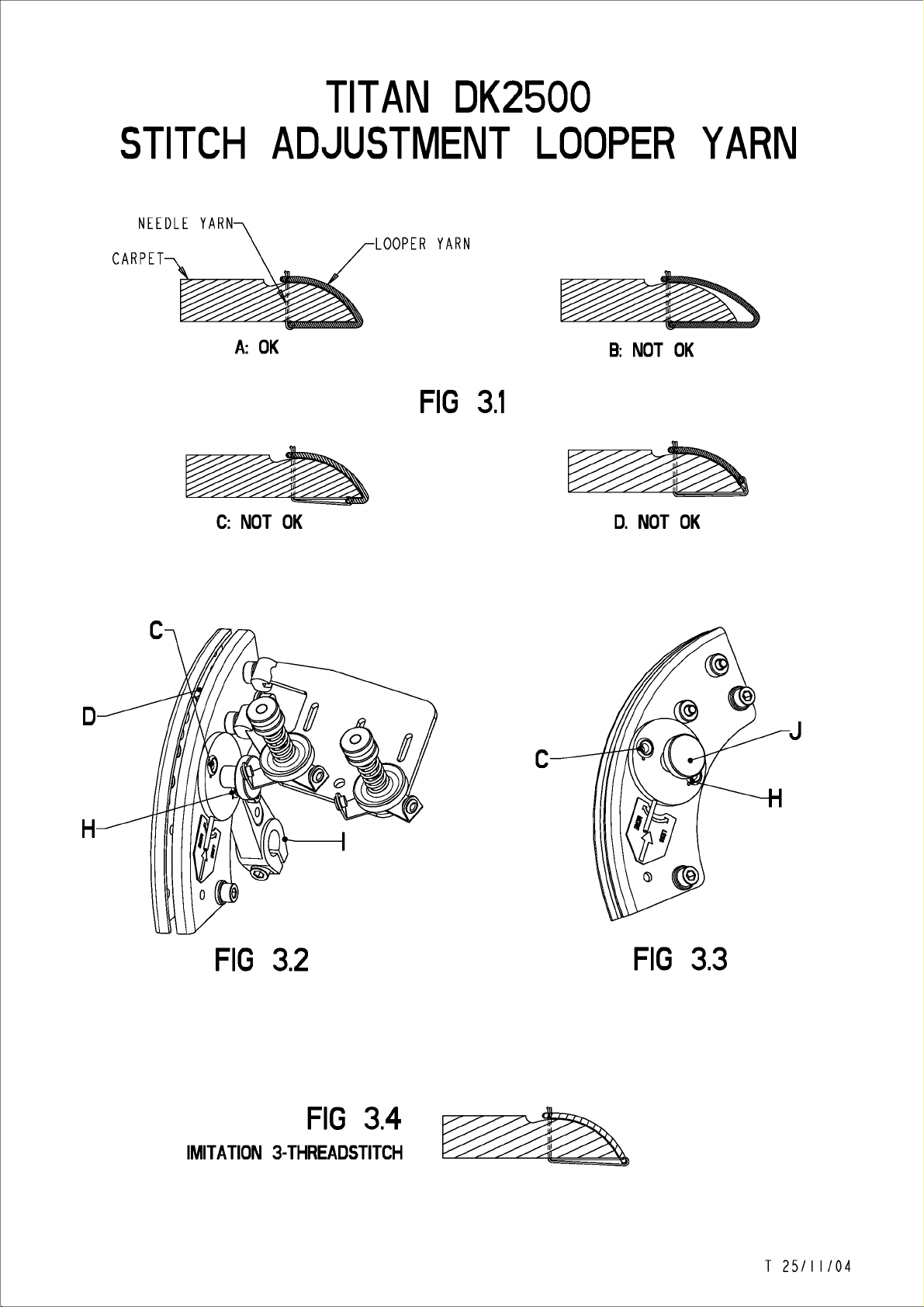
1. Chain yarn feed
It is recommended to keep the pressure on the springs to a minimum on the thread
tensioners A, B and G (FIG 2.1).
Note:
Always make sure the chain yarn is positioned underneath the yarn drawing lever D
(or “take-up”) (see FIG. 2.1-3.2). Failure to do so, will result in improper stitch
formation. To avoid this, check if the machine has been threaded properly (see
chapter 2b).
FIG 3.1A:
absolutely uniform tensions.
FIG 3.1B:
FIG 3.1C&D:
Correct stitch formation, the chain yarn and the needle thread have both
Either insufficient chain yarn tension, or excessive needle thread tension
Either excessive chain yarn tension, or insufficient needle thread tension
With the take-up lever D correctly set, the amount of thread thus fed will assure
successful overlocking of the carpet.
In the event of insufficient thread feed (or with thicker carpets), however, undue
tension will be placed on the chain yarn along the edges of the carpets, which in turn
will pull the needle thread from the carpet backing (see figure 3.1C).
To remedy: adjust the take-up lever D slightly in the direction of C3 (see figure 3.5).
Conversely in the event of excessive thread feed (or with thin carpets), the chain yarn
will be found to be slack around the carpet edges (see figure 3.1B).
To remedy: adjust the take-up lever D slightly in the direction of C1 (see figure 3.5).
If the machine isn’t equipped with RFR fine adjustment gear (see figure 3.3), the
position of take-up lever D is to be changed as follows:
Untighten the screw of the arm I (figure 3.2) and place the take-up lever D into the
wanted position (higher=less thread, lower=more thread) afterwards, tighten the
screw of arm I again.
RFR fine adjustment assembly: standard in the new machines (from 2004 on)
To adjust the thread feed : loosen the screw J (FIG 3.3). Push the bar (lever)
towards “+” to increase thread feed, towards “-“ to decrease thread feed.
Note: For the typical two-thread overlock stitch, insert the chain yarn in the C eye as
illustrated in figure 3.2 and 3.3
For special stitch formation similar to a three-thread stitch (see figure 3.4), pass the
chain yarn through the H eye (see figure 3.2 and 3.3) and then adjust thread feed so
that the stitch thus formed is similar to the one shown in figure 3.4.
Page 11

TIT
DK 2500 MANUAL E PAGE 10
AN
DK2500
STITCH
FIG
3.6
ADJUSTMENT
STITCH
WIDTH
STITCH
STANDARD
STITCH
ADJUSTEMENT
FIG
WITH
3.7
ADJUSTEMENT
RPR
K
M
L
T
25/11/04
Page 12

DK 2500 MANUAL E PAGE 11
FIG 3.5
2. Stitch density setting (per cm)
I
a. On standard equipment
• Unscrew and remove the big knurled screw to allow access to nut K
(FIG 3.6).
• Turn the hand-wheel by hand to secure the needle in its bottommost position.
• Holding the hand-wheel in position with your right hand, unscrew (counter
clockwise) the nut K by ½ a turn using a M10 hex key.
• Place the nut K either forward or backward as appropriate. Thus you will
increase/reduce stitch density per cm (see figure 3.6).
• Retighten the nut K and replace the knurled screw on the sewing head!
b. With the stitch density regulator (RPE/DK 2500 SEE OPTIONAL ATTACHMENTS)
The RPE option as illustrated in figure 3.7 is fitted on to the left-hand side of the
sewing machine.
• Loosen both L screws.
• Turn the disc M counter clockwise.
• By turning the adjuster screw N clockwise,
By turning the adjuster screw N counter clockwise,
• For best results, we recommend to sew first on a small piece of carpet to see if
the correct amount of stitches per cm has been obtained.
• To secure the adjuster screw N into position, turn disc M clockwise until it can
not move further.
• Slightly tighten both L bolts to lock the settings.
you increase stitch density.
you decrease stitch density.
,
The RPE option is designed to guarantee optimum sewing result with any carpet
quality and/or yarn thickness.
Page 13

TIT
DK 2500 MANUAL E PAGE 12
AN
DK2500
NEEDLE
PLACE
NEEDLEBAR
REPLACEMENT
IN
HIGHEST
POSITION.
D
&
ADJUSTMENT
X
R
FIG
4.1
T
26/11/04
Page 14

Chapter 4: Mechanic adjustment of the sewing
DK 2500 MANUAL E PAGE 13
head.
!! Remark: Always switch off the motor before adjusting wh
1. The needle
The table below is a breakdown of typical needle types.
Type: Description Suitable for:
7713/230T Standard needle Medium carpets
7713-99/230T Square pointed needle Heavy car carpets
7713-99/230TP Needle with flat holder Heavy Car carpets
7713-99/230TPC Golden needle For automatic systems DK 4600
7713-200T Medium thick needle Light carpets
7713/180T Medium thin needle Light carpets
7713/160T Thin needle Blankets
7713/130T Ultra thin needle Fabrics (butt-seamer DK 2500E
and 2510E series)
atever part of the machine !!
For special purposes, please contact our service department for additional information.
tel.: ++32/2-216.31.40
a. How often are the needles to be replaced?
Considering the typical up and down movement of needles on DK 2500 series sewing
machines is about 2.800 movements per minute, needles will need replacing after a
couple of days as they become blunt, thin, and the groove disappears, thus result :
false stitches.
Assuming the machine is used for one 8-hour shift, the needle will have pierced the
carpet approximately 6 million times in one week (40h). Depending on carpet quality,
we advise to replace the needle at least once a week.
b. Needle replacement
While sewing, a circle of dust will be built up around the needle holder. It is
important to remove first any dust that may have accumulated, prior to fitting a
replacement needle! If not, dust accumulation in the needle holder may probably
modify the exact movement of the needle, which will result in false or bad stitch
formation and may drastically decrease the life time of internal parts.
very
Page 15

PART
NR.
NEEDLE
NR.
Needle
DK
2500.
guide.
- 25559-230
- 25559-200
-7713/230
- 7713-99/230
-
7713 / 200
I
HEAVY C ARPETSI
25559A
PART
-
25559A
25559B
NR.
NEEDLE
-
7713 / 110
-7713/130
-
7713 / 160
- 7
713 / 180
- 7713 /
NR.
200
.
!NORMAL
CARPETS!
Page 16

SET 25559A
Afstelling
- Stukken 25559A
worden
bevestigd
- Stukken 25559A
maximaal
-
De
.
met
-
We
onderste
-
We
25559B
er
achterwaartse
-
We
vast.
Adjustment
van
los
op
met
openschuiven,
afstelling
een
nieuwe
zetten
sluiten
geen
schroeven,
de
dode
stukken·25559A
rond
voorwaartse
of
de
naaldgeleiding.:..
en
25559B
de
naaldplaat
schroef
en
gebeurt
naald.
risald
punt.
de
naald
speling
schroef
the
25559V.
25559B
steeds
in
haar
zodat
of
meer
25559V
needle-g~
en
is.
Reglage
-
Pieces
fixees
aiguille
-
Ouvrir
25559B
-
L'ajustement
avec
Positioner
point
- Fermer
25559B
si
j
eu en
-
Serrer
une
bien
du
guide-aiguille.
25559A
mobile
lea
maximum.
mort
les
auteur
qu1il
avant
la
et
sur
avec
la
pieces
se
nouvelle
l'aiguille
inferieur.
pieces
de
n'y a plus
ou
vis
25559V,
25559B
la
plaque
vis
25559V.
25559A
fait
toujours
aiguille
a
25559A
l'aiguille
en
arriere
sont
a
et
•
son
et
de.
~
Einstellung der nadelfuhrung.
-
Fix
parts
·mobile o~
with
- Push
25559B
- Adjustment
done
-
Put
the·
death
-
Close
around
way
that
backward
-
Fix
the
25559A
the
screw
the
with
25559V. ·
parts
maximum
must
a new
needle
point,
parts
25559A and
the
needle
there
or
forward
screw 25559V.
and
25559B
needle
25559A and
open.
in
is
plate
always
needle.
her
in
such
no more
play.
be
lowest
25559B
a
_.,,
-
Teile
milssen Mobil
Platte
Schraube
-
Teile
maximal
-
Die
unterste
-
Schlieszen
und 25559B rund
-
25559A und 25559B
befestigt
25559A und 25559B
aufschieben.
Einstellung
geschehen
Setzen
sodasz
ri.i.ckwarts
Schraube
schrauben.
Sie
es
auf
25559V
mit
die
Tode
Sie
kein
Spiel
25559V
die
Nadel-·
werden
•.
musz immer
einer
Funkt.
neue
Nadel
Teile
vorwarts
die
mehr
fest
in
25559A
Nadel
gibt.
mit
Nadel
Ihre
oder
Page 17

TIT
AN
DK2500
NEEDLE
FLAT
SIDE
NEEDLE
WITH
LOWER
5
REPLACEMENT
H
PARALLEL
LOOPER
FIG
4.2
&
ADJUSTMENT
w
.!!!
SEE
5
FIG
DETAIL
4.3
A
DETAIL
SCALE
LOWEST
OF
NEEDLE
A
3/
I
POSITION
POINT
T
07/01/2005
Page 18

DK 2500 MANUAL E PAGE 15
To replace worn out or broken needles, proceed as follows:
• Loosen the screw H (see figure 4.1) and remove the needle.
• Remove accumulated dust in the needle-holder.
• Fit in a replacement needle. Make sure to position and push the new needle
fully home into the needle-holder.
• Be sure the groove of the needle faces the front and that the flat side on the
back of the needle is mounted parallel to the flat face of the lower looper S (FIG
4.2). To check this, turn the hand-wheel by hand and have the lower looper and
the needle cross.
• Retighten the screw H.
• Check the needle position according to chapter 4.1c .
c. Needle height adjustment
With the needle having reached the top of its stroke, distance between the needle
point and the needle plate must be exactly 23 mm (see figure 4.1).
For fine adjustment of the needle height:
• Loosen the screws H first while holding the needles by hand (see figure 4.1).
• Push the needle against the screw F.
• If adapting screw F, you first have to unscrew the screw G
• By turning the screw F, the needle height will be increased or reduced
(clockwise/counter-clockwise).
.
• Retighten the screw G and also screw H
!! The following instructions are restricted to qualified personnel only !!
d. Replacing the needle bar and adjusting the needle height.
Replacing the needle bar
• Loosen the screws A and remove the worn out needle bar B (figure 4.1) from
clamp C.
• Loosen the screw X and recuperate the needle holder W.
• Fit the needle holder W into the new needle bar and tighten screw X to secure
the needle bar.
• Place a new needle in the needle holder W.
• Check the parallelism between the needle and the needle bar. If these 2 parts
are not parallel, it is strongly advised to replace the needle holder W
• Fit the new needle bar into the holder C and lightly tighten the screws A.
• Turn the hand-wheel by hand to place the needle at the top of its stroke
(highest position).
• In this position, the distance between the needle point and the needle plate
(25558) must be exactly 23 mm (figure 4.1).
Adjusting the needle height
• Loosen the screws A in FIG 4.1. By doing this, the holder C will loose its grip
on needle bar B (figure 4.1).
• The position of the needle can be adjusted to the top dead point being 23 mm.
• Retighten the screws A.
• Verify, by turning the hand-wheel by hand, if the needle is moving up and down
right in the centre of the needle plate (Fig.4.1 Detail).
Optimum needle thread loop formation setting
To achieve optimum needle thread loop formation, make sure the position of the
needle with respect to the lower looper S, is correct.
• Turn the hand-wheel by hand and bring the needle to reach the bottom of its
stroke (lowest position)
• Turn the hand-wheel a little further (see figure 4.3) until the needle has travelled
1,2mm on the upward stroke.
• In this position, the point of the lower looper should just pass behind the needle
as seen in Fig. 4.3 + Detail A.
Page 19

TITAN
DK 2500 MANUAL E PAGE 16
DK25OO
UPPER
LOOPER
ADJUSTMENT
5mm
T
FIG
V
4.4
T
29/11/04
Page 20

DK 2500 MANUAL E PAGE 17
2. Upper looper
a. Preparatory work
In order to replace the upper looper, the cover and some other parts have to be
removed. We strongly advise to proceed as follows:
• Loosen the two screws 25833V and remove the protective plate (25833).
• Release the pressure on the pressure foot.
• Loosen the two screws 25556V and remove the needle (7713/230T).
• Loosen the two screws 25558V and remove the needle plate (25558).
• Loosen the screw 25804VL and remove the threader unit (25804).
• Loosen the screw 25655V and remove the lower blade (25655).
• Loosen the screw 25744V and remove the feed dog (25744).
• Loosen the two screws 25700V and remove the upper looper (25705).
b. Replacing the upper looper
• Turn the handwheel by hand and push the lower looper to its furthermost
backward position. This action will give the operator access to the screws T
(FIG 4.4).
• Unscrew these and replace the worn out upper looper with a new one (25705).
• Retighten the screws T
• Turn the hand-wheel by hand for the upper looper to reach its top of its stroke.
• Make sure the outer end of the upper looper extends for 5mm beyond the edge
of the needle, as illustrated in figure 4.4.
If this is not the case, adjust correct position via the screws T
c. Upper looper fine adjustment
Our sewing machines are factory-set to sewing medium quality carpets with medium
quality yarn
When using thicker/finer yarns deviating from the factory-set typical yarn thickness,
we recommend that the position of the upper looper be adjusted as follows:
Loosen the T screws (figure 4.4) and turn the hand-wheel by hand for the upper
looper to reach the top of its stroke (highest position).
s.
.
as in figure 4.4.
In the event of thick yarns, move the point of the upper looper a little to the left
(0,5mm maximum), so that the distance between the outer end of the upper looper
and the edge of the needle is 5,5mm.
In the event of fine yarns, move the outer end of the upper looper a little to the right
(0,5mm maximum), so that the distance between the outer end of the upper looper
and the edge of the needle is 4,5mm.
Note: With every change of the upper looper, check the following points while turning
the hand-wheel by hand:
When the upper looper V and the lower looper S (figure 4.5) cross one another on the
upper looper upward stroke, the end of the upper looper S must travel right in the
centre of the recess of the lower looper S.
On its upward stroke towards the needle, the end of the upper looper V, mus
touch the lower looper S and needle (no contact is allowed). Should this occur
anyway, follow the steps below. After having adjusted the upper looper, put back all
parts and put back again the pressure on the pressure foot.
t not
Page 21

TITAN
DK25OO
LOWER
LOOPER
0
ADJUSTMENT
0
w
u
M
0
N
II
POINT
V
IN
V
OF
MIDDLE
LOWER
UPPER
OF
LOOPER S II
LOOPER
CUTOUT
IN
FIG
4.5
T
30/11/04
Page 22

DK 2500 MANUAL E PAGE 19
!! The following instructions are restricted to qualified
personnel only !!
With the upper looper in its bottom dead centre, make sure the outer end of the upper
looper aligns with the centre of the screw (25557V) that fixes the needle bar bushing
(Fig. 4.3).
Should this not be the case, loosen the two 25698VL screws (see part list – Upper
looper mechanism) and bring the upper looper in the right position as described in
previous paragraph 4.2b.
Turn the hand-wheel by hand for the upper looper to reach its upper position and
make sure the outer end of the upper looper extends for 5 mm beyond the edge of
the needle (see figure 4.5).
Should this not be the case, loosen the two 25698VL screws and bring the upper
looper in the right position as described in previous paragraph -
b. replacing the upper looper
3. The lower looper
a. Preparatory work
To gain access to the lower looper, proceed as follows:
• Turn to figure 2.1, titled ‘Threading Diagram’, and locate the screw-on/off fitting
cap with the wording OIL marked on it.
• Loosen and remove the cap. This will give the operator access to the lower
looper.
b. Replacing the lower looper
To replace a worn out lower looper, proceed as follows:
• Use an open ended spanner n° 6 to retain the base W (Fig. 4.5) of the lower
looper into position while using an open ended spanner n° 10, loosening the nut
K for ½ a turn (MAXIMUM).
• Gently unscrew the worn out lower looper and remove it.
• Fit in the replacement lower looper.
Note: Prior to fixing the lower looper into position, perform positioning of the lower
looper relative to the recess on the rear of the needle as described below (see figure
4.2-4.3-4.5).
Turn the hand-wheel by hand while making sure that when the lower looper is
passing beyond the needle, both flat faces on both parts are parallel. The lower
looper can under no condition touch the needle !
In the event of exact parallelism as shown in figure 4.2, retain the lower looper S in
position using an open ended spanner n° 6, while screwing the block nut K (figure
4.5) through ½ a turn, using an open ended spanner n° 10.
Page 23

TITAN
DK 2500 MANUAL E PAGE 20
DK25OO
LOWER
LOOPER
0
ADJUSTMENT
0
w
u
M
0
N
II
POINT
V
IN
V
OF
MIDDLE
LOWER
UPPER
OF
LOOPER S II
LOOPER
CUTOUT
IN
FIG
4.5
T
30/11/04
Page 24

DK 2500 MANUAL E PAGE 21
!! The following instructions are restricted to qualified personnel only !!
c. Adjusting the upper looper to the lower looper
Prior to adjusting, perform the steps detailed in previous paragraphs.
On the upper looper upward stroke and with the lower looper moving to its forward
dead point, as illustrated in figure 4.5, the outer end of the upper looper V must pass
right in the centre of the recess of the lower looper S.
In other words, when both loopers cross each other, the end of the upper looper V
must pass right in the centre of the recess of the lower looper S.
Should this not be the case, follow the steps below to adjust the position of the lower
looper inside
• Loosen the screw R, therefore enabling the lever M to move freely on the shaft
(Fig. 4.1).
• Turn the hand-wheel whilst making sure that the outer end of the upper looper
passes right in the centre of the recess located at the rear of the lower looper,
when both loopers cross one another.
• If necessary, adjust the position of the lever M.
• Retighten the screw R thus securing the lever M position.
d. Adjusting the distance between needle and lower looper
Prior to adjusting, perform the steps detailed in previous paragraphs.
the sewing machine.
Turn the hand-wheel such that the outer end of the lower looper S passes the rear of
the needle. Make sure that the distance between the needle and the lower looper is in
the range 0.2mm to 0.3mm (Fig. 4.2).
(These measures apply to machines equipped with standard needles, size 230.
When using different needles, contact our Service Department at +32/2.216.31.40).
If the distance measured above is either inferior to 0.2mm or superior to 0.3mm,
proceed as follows.
• Loosen the screw Q of figure 4.5.
• Manually move the part N forward or backward, so that the distance between
the needle and the lower looper is in the range 0.2mm to 0.3mm (figure 4.2).
Gently turn the flying wheel by hand while making sure that the distance between the
outer end of the upper looper V and the flat face of the recess on the rear of the lower
looper S is 1mm (see figure 4.5).
Should this not be the case, follow the steps below.
Unscrew the screw U (see figure 4.5) by 1/4 of a turn maximum
to move freely in the holder M. Manually move the part L a little forward or backward
whilst ensuring the distance between the outer end of the upper looper and the rear
of the lower looper is approximately 1 to 2 mm (see figure 4.5). Retighten the screw
U.
Note: After every change, it is essential to check the position of the outer end of the
upper looper in relation to the rear of the needle and if necessary to adjust as
described in the previous chapters.
Upon completion of any such adjustment, turn the handwheel and re-check the
position of the upper looper relative to the lower looper. Adjust, if necessary.
For each adjustment, remember to re-check all the positions and adjust until the
positions of the three parts are concordant.
, to enable the part L
Page 25

TITAN
DK2500
KNIFE
ADJUSTMENT
A
VIEW
A >
~--------------------
------------------------
~·-~-·-~-·-~-·-~-·-~-·-~-·--
_-
0
0
C
FIG
LOWER
KNIFE
4.6
IN
HIGHEST
B
POSITION
VIEW
A
- I
,Q
I
EE
EE
-=
=-
:z: ><
-<C
:a;;: :a;;:
E
E
Lt")
-
Lt")
f-
EE
.....JEE
::::, <.D
<C
u...
><:Z:
u..J<C-
c:,
:a;;: :a;;:
(")
T
30/11/04
Page 26

DK 2500 MANUAL E PAGE 23
4. The cutting motion
For an extended operational life, the lower knife (25655) and the upper knife (25656)
of TITAN DK 2500 series machines are equipped with special hardened steel.
a. Renewing the upper knife
• Loosen the screw C (see figure 4.6).
• Entirely remove the screw A retaining the upper knife.
• Replace the worn upper knife with a new item (25656) and retighten screw A.
b. Renewing the lower knife
• Unscrew the screw B (see figure 4.6) retaining the lower knife.
• Replace the worn lower knife with a new one (25655) and retighten the screw
B.
c. Knife fine adjustment
Upon completion of knife renewal, take great care to align both knifes by turning the
screw C.
Note: Do not over-tighten the screw C as this will put both knifes too close to one
another thus leading to their early wear. (The mobile under knife will produce a cut in
the upper knife.)
Secondly, as the knifes experience trouble sliding because too tightly screwed,
extreme pressure should be produced by the internal parts to drive the cutting motion,
which in turn will promote early wear or jam the internal parts.
d. Aligning the low
With the needle having reached its lowest stroke, ensure that the lower knife
protrudes 6 to minimum 3 mm above the needle plate (see figure 4.6). If this is not
the case renew both knives
er blade with the needle plate
5. The presser foot
For optimum sewing performance, a good control of presser foot pressure is very
important.
Insufficient presser foot pressure will lead feed-dog to skid, which will endanger the
continued health of the feed-dog on the one hand, and will result in irregular stitch
formation on the other hand. When overlocking soft foam rubber backed carpets, the
carpet backing will be damaged.
However, carpet backings will show only small, virtually invisible signs of wear when
presser foot pressure is correct.
Conversely, when the presser foot pressure is too high, the feed-dog will break!
Typical rated torque setting is 80 N/m. Use a torque wrench for correct presser foot
setting (see figure 4.8).
Following is a breakdown of the presser feet available (for schematic representations
refer to fig. 14A).
Page 27

TITAN
DK 2500 MANUAL E PAGE 24
DK2500
PRESSURE
ON
PRESSUREFOOT
BON
FIG
4.8
"<I"
E
E
T 01/12/04
Page 28

DK 2500 MANUAL E PAGE 25
Part Suited for…
25583 Standard presser foot
25583 BIS Presser foot for fine delicate fabrics
30583K Presser foot for blankets; used in conjunction with
guides.
25583EEK Presser foot for carpets fine overlocking, typical
stitch width 5,5mm
25583B Buttseamer presser foot
25583E
BIS
Buttseamer presser foot for fine delicate fabrics.
25280 For car carpets DK 2500Ag
Page 29

DK 2500 MANUAL E PAGE 26
6. Feed-dog
With every up and down movement of the feed dog, some dust will accumulate. To
avoid excessive dust accumulation, we recommend to blow carefully the space
underneath the needle plates with compressed air at the end of each shift.
Furthermore, remove the stitch plate every two weeks, to thoroughly remove any
compressed dust built up underneath.
Failure to do so will result in dust mixing with the machine’s oil. The sticky black
mixture formed will act as abrasive paper and score critical components, resulting in
a premature wearing out of internal components such as bearings.
Available feed-dog types:
Part Suited for…
25744 Standard, for medium quality carpets
25744K With fine teeth, for light or delicate
materials
25744CAR Heavy duty
25744KPCAR Heavy duty, with pyramid shaped teeth
Page 30

DK 2500 MANUAL E PAGE 27
7. Chain guide
For optimum stitch formation, it is recommended for the chain guide to be adjusted to
the carpet thickness.
Find hereunder the available chain guides :
Part Number Suited for…
25560 Normal carpets
25560B High pile carpets
25560H Heavy carpets
25560EE Normal carpets with small-sized over locking (2500 EEK)
30560GR Normal carpets with tape insertion
25560C Blankets (DK 2500C type)
25560K Butt-seamer (DK 2500 E type)
8. Stitch plate finger
The type of stitch plate finger used will depend on different factors such as :
• Thickness of yarn
• Thickness of needle
• Stitch width
Phone our technical department for advice or mail : +32-2-216.31.40
Page 31

DK 2500 MANUAL E PAGE 28
CHAPTER 5 : MAINTENANCE SCHEDULE
MAINTENANCE SCHEDULE : to prolong the life time of your TITAN Machine.
TO DO EVERY 8 HOURS (+/- DAY)
• Blow clear the machine with compressed air at the end of each shift!
TO DO EVERY 40 HOURS (WEEK)
• Change needle every 40 working hours .
• Before replacement of the needle, thoroughly remove any dust that may have
accumulated round the needle holder.
• Remove dust beneath both the stitch plate and the feed-dog
once a week!
• Check oil level every week + add oil accordingly.
TO DO EVERY 200 HOURS (MONTH)
• Change the oil once a month minimum! OIL TYPE : 15W30
• Check and if necessary replace any worn out parts such as
loopers, knives, needle guide, chain guide with new ones.!
TO DO EVERY YEAR
• Check if the parts are still mounted tight
lower looper – needle bar – knifes and other parts. Open up the machine and
replace necessary parts such as bearings, and others
ly, if there is no play on the upper and
• If you have no maintenance engineer, you can send back your sewing head,
and the company DE KONINCK will give se
or sales department at TEL +32-2-216.31.40 or by email at :
info@titansew.com
rvice to you. Consult our technical
Page 32

PARAMETER SETTINGS ON THE EFKA MOTOR
PLEASE NOTE
As the Controller is programmed with a memory key from Titan and you want to
change some parameters. It is necessary to erase the settings from the memory key by
changing the parameter 399 cFP.
To activate this parameter you have to do following steps :
1. Enter Code 3112
2. Go to parameter 399 and push ENTER
3. Push on the arrow and ENTER again CODE 3112
4. Press two (2) times on P
5. Power off, wait for one second
6. Power on.
ELECTRONIC MOTOR SETTINGS EFKA :DC 1500/1550 SERIES
USE SETTINGS ONLY FOR DK 2500 OVEREDGING MACHINES!!
- POWER OFF
- POWER ON AND PRESS P KEY
- PRESS >> KEY
- SET SUPPLIER LEVEL CODE NUMBER 3112
- PRESS E KEY
- PARAMETER .2.0.0. IS DISPLAYED
- PRESS KEY >> AND CHANGE PARAMETER .2.0.0. TO .1.1.1.
- PRESS E KEY
- SET VALUE ON 2800 BY PRESSING + OR – KEY
- PRESS E KEY
- PARAMETER .1.1.2. IS DISPLAYED
- PRESS >> KEY AND CHANGE PARAMETER .1.1.2. TO .1.1.9.
- PRESS E KEY
- SET VALUE ON 3 WITH + OR – KEY
- PRESS E KEY
- PARAMETER .1.2.1. IS DISPLAYED
- PRESS >> KEY AND CHANGE PARAMETER .1.2.1. TO .1.5.3.
- PRESS E KEY
- SET VALUE ON 15 WITH + OR – KEY
- PRESS E KEY
- PARAMETER .1.5.5. IS DISPLAYED
- PRESS >> KEY AND CHANGE PARAMETER .1.5.5. TO .5.0.0.
- PRESS E KEY
- SIR- IS DISPLAYED
- PRESS >> KEY
- PARAMETER .2.9.0. IS DISPLAYED
- PRESS E KEY AND SET VALUE TO 05WITH + OR – KEY
- PRESS E KEY
- PARAMETER .1.6.1. IS DISPLAYED
- PRESS E KEY AND SET VALUE TO 0 WITH + OR – KEY
- PRESS E KEY
- PARAMETER .2.7.2. IS DISPLAYED
- PRESS E KEY AND SET VALUE TO 0739 WITH + OR – KEY
- PRESS E KEY
Page 33

- PARAMETER .2.7.0. IS DISPLAYED
- PRESS E KEY ANDSET VALUE TO 3 WITH + OR – KEY
- PRESS E KEY
- PARAMETER .4.5.1. IS DISPLAYED
- PRESS E KEY AND TURN HANDWHEEL CLOCKWISE AND
- SET NEEDLE ON LOWEST POINT
- PRESS E KEY
- PARAMETER .4.5.3. IS DISPLAYED
- PRESS E KEY AND TURN HANDWHEEL CLOCKWISE AND
- SET NEEDLE ON TOP POINT
- PRESS E
- PARAMETER .2.9.0. IS DISPLAYED
- PRESS TWO TIMES P KEY
- RUN THE MACHINE FOR ONE (1) SECOND
- POWER OFF
- POWER ON
 Loading...