

Page 1
Owner’s Manual
Notice d’utilisation
Manual del Propietario
Do not use this equipment before
reading this manual!
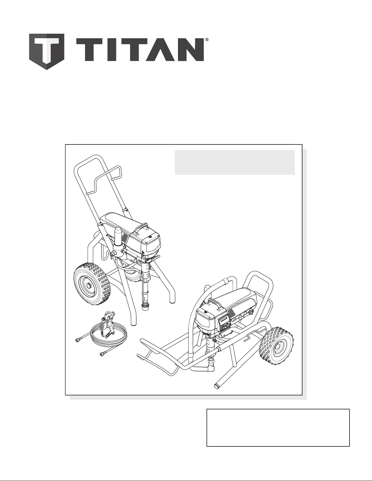
IMPACT 840
Airless Sprayer
NOTE: This manual contains important
warnings and instructions. Please
read and retain for reference.
Model 805-009
Model 805-010
Register your product online at:
www.titantool.com
Serial Number* _ _ _ _ _ _ _ _ _ _
* See pages 6 and 55 for location
Anti-Theft Digital Lockout
Security Code
_ _ _ _
0816 • © Titan Tool Inc. All Rights Reserved. Form No. 0552882G
Page 2
Important Safety Information
Grounded Outlet
Grounding Pin
Cover for grounded outlet box
Read all safety information before operating the
equipment. Save these instructions.
Indicates a hazardous situation which, if not avoided,
could result in death or serious injury.
To reduce the risks of re or explosion, electrical shock
and the injury to persons, read and understand all
instructions included in this manual. Be familiar with the
controls and proper usage of the equipment.
Grounding Instructions
This product must be grounded. In the event of an electrical short circuit,
grounding reduces the risk of electric shock by providing an escape wire
for the electric current. This product is equipped with a cord having a
grounding wire with an appropriate grounding plug. The plug must
be plugged into an outlet that is properly installed and grounded in
accordance with all local codes and ordinances.
WARNING - Improper installation of the grounding plug
can result in a risk of electric shock.
If repair or replacement of the cord or plug is necessary, do not connect
the green grounding wire to either at blade terminal. The wire with
insulation having a green outer surface with or without yellow stripes is
the grounding wire and must be connected to the grounding pin.
Check with a qualied electrician or serviceman if the grounding
instructions are not completely understood, or if you are in doubt as
to whether the product is properly grounded. Do not modify the plug
provided. If the plug will not t the outlet, have the proper outlet
installed by a qualied electrician.
This product is for use on a nominal 120 volt circuit and has a grounding
plug that looks like the plug illustrated below. Make sure that the product
is connected to an outlet having the same conguration as the plug. No
adapter should be used with this product.
conductive or grounded high-pressure airless paint sprayer hoses
specied by the manufacturer.
• Verify that all containers and collection systems are grounded to
prevent static discharge.
• Connect to a grounded outlet and use grounded extension cords
(electric models only). Do not use a 3 to 2 adapter.
• Do not use a paint or solvent containing halogenated
hydrocarbons. Such as chlorine, bleach mildewcide, methylene
chloride and trichloroethane. They are not compatible with
aluminum. Contact the coating supplier about compatibility of
material with aluminum.
• Keep spray area well ventilated. Keep a good supply of fresh air
moving through the area to keep the air within the spray area free
from accumulation of ammable vapors. Keep pump assembly in
well ventilated area. Do not spray pump assembly.
• Do not smoke in the spray area.
• Do not operate light switches, engines, or similar spark producing
products in the spray area.
• Keep area clean and free of paint or solvent containers, rags, and
other ammable materials.
• Know the contents of the paint and solvents being sprayed.
Read all Material Safety Data Sheets (MSDS) and container labels
provided with the paints and solvents. Follow the paint and
solvent manufacture’s safety instructions.
• Place pump at least 25 feet (7.62 meters) from the spray object in
a well ventilated area (add more hose if necessary). Flammable
vapors are often heavier than air. Floor area must be extremely
well ventilated. The pump contains arcing parts that emit sparks
and can ignite vapors.
• Plastic can cause static sparks. Never hang plastic to enclose spray
area. Do not use plastic drop cloths when spraying ammable
material.
• Fire extinguisher equipment shall be present and working.
WARNING: INJECTION INJURY
A high pressure paint stream produced by this equipment
can pierce the skin and underlying tissues, leading to
serious injury and possible amputation. See a physician
immediately.
IMPORTANT: When the sprayer is used with a generator
or uncontrolled line voltage, the use of Titan’s “Line Surge
Protector” (P/N 800-935) is recommended.
WARNING: EXPLOSION OR FIRE
Solvent and paint fumes can explode or ignite. Property
damage and/or severe injury can occur.
PREVENTION:
• Do not spray ammable or combustible materials near an open
ame, pilot lights or sources of ignition such as hot objects,
cigarettes, motors, electrical equipment and electrical appliances.
Avoid creating sparks from connecting and disconnecting power
cords.
• Use extreme caution when using materials with a ashpoint
below 100ºF (38ºC). Flashpoint is the temperature that a uid can
produce enough vapors to ignite.
• Paint or solvent owing through the equipment is able to result
in static electricity. Static electricity creates a risk of re or
explosion in the presence of paint or solvent fumes. All parts
of the spray system, including the pump, hose assembly, spray
gun and objects in and around the spray area shall be properly
grounded to protect against static discharge and sparks. Use only
2 © Titan Tool Inc. All rights reserved.
PREVENTION:
• Do not aim the gun at, or spray any person or animal.
• Keep hands and other body parts away from the discharge. For
example, do not try to stop leaks with any part of the body.
• NEVER put your hand in front of the gun. Gloves will not provide
protection against an injection injury.
• ALWAYS keep the tip guard in place while spraying. The tip guard
provides some protection but is mainly a warning device.
• Only use a nozzle tip specied by the manufacturer.
• Use caution when cleaning and changing nozzle tips. In the
case where the nozzle tip clogs while spraying, ALWAYS lock
gun trigger, shut pump o, and release all pressure before
servicing, cleaning tip or guard, or changing tip. Pressure will
not be released by turning o the motor. The PRIME/SPRAY
valve or pressure bleed valve must be turned to their appropriate
positions to relieve system pressure. Refer to PRESSURE RELIEF
PROCEDURE described in the pump manual.
• Do not leave the unit energized or under pressure while
unattended. When the unit is not in use, turn o the unit and
relieve the pressure in accordance with the manufacturer’s
instructions.
• High-pressure spray is able to inject toxins into the body and
cause serious bodily injury. In the event that injection occurs,
seek medical attention immediately.
• Check hoses and parts for signs of damage, a leak can inject
material into the skin. Inspect hose before each use. Replace any
damaged hoses or parts. Only use TITAN original-high-pressure
hoses in order to ensure functionality, safety and durability.
English English
Page 3
Important Safety Information
• This system is capable of producing 3300 PSI / 228 Bar. Only
use replacement parts or accessories that are specied by the
manufacturer and that are rated a minimum of 3300 PSI. This
includes spray tips, nozzle guards, guns, extensions, ttings, and
hose.
• Always engage the trigger lock when not spraying. Verify the
trigger lock is functioning properly.
• Verify that all connections are secure before operating the unit.
• Know how to stop the unit and bleed pressure quickly. Be
thoroughly familiar with the controls. Pressure will not be
released by turning o the motor. The PRIME/SPRAY valve
or pressure bleed valve must be turned to their appropriate
positions to relieve system pressure. Refer to PRESSURE RELIEF
PROCEDURE described in the pump manual.
• Always remove the spray tip before ushing or cleaning the
system.
NOTE TO PHYSICIAN:
Injection into the skin is a traumatic injury which can lead to
possible amputation. It is important to treat the injury as soon as
possible. DO NOT delay treatment to research toxicity. Toxicity
is a concern with some coatings injected directly into the blood
stream. Consultation with a plastic surgeon or reconstructive hand
surgeon may be advisable.
WARNING: HAZARDOUS VAPORS
Paints, solvents, insecticides, and other materials can
be harmful if inhaled or come in contact with the body.
Vapors can cause severe nausea, fainting, or poisoning.
PREVENTION:
• Use a respirator or mask if vapors can be inhaled. Read all
instructions supplied with the mask to be sure it will provide the
necessary protection.
• Wear protective eyewear.
• Wear protective clothing as required by coating manufacturer.
WARNING: GENERAL
Can cause severe injury or property damage.
PREVENTION:
• Always wear appropriate gloves, eye protection, clothing and a
respirator or mask when painting.
• Do not operate or spray near children. Keep children away from
equipment at all times.
• Do not overreach or stand on an unstable support. Keep eective
footing and balance at all times.
• Stay alert and watch what you are doing.
• Do not operate the unit when fatigued or under the inuence of
drugs or alcohol.
• Do not kink or over-bend the hose. Airless hose can develop leaks
from wear, kinking and abuse. A leak can inject material into the
skin.
• Do not expose the hose to temperatures or pressures in excess of
those specied by manufacturer.
• Do not use the hose as a strength member to pull or lift the
equipment.
• Use lowest possible pressure to ush equipment.
• Follow all appropriate local, state and national codes governing
ventilation, re prevention and operation.
• The United States Government Safety Standards have been
adopted under the Occupational Safety and Health Act (OSHA).
These standards, particularly part 1910 of the General Standards
and part 1926 of the Construction Standards should be consulted.
• Before each use, check all hoses for cuts, leaks, abrasion or
bulging of cover. Check for damage or movement of couplings.
Immediately replace hose if any of those conditions exist. Never
repair a paint hose. Replace with a conductive high-pressure
hose.
• Do not spray outdoors on windy days.
• Always unplug cord from outlet before working on equipment
(electric models only).
Specications
Gallons per minute (GPM) 1.0 (3.75 LPM)
Maximum tip sizes 0.032
Maximum pressure 3300 PSI (22.8 MPa)
Power 2.3 HP Brushless DC Motor, 100~120V
AC, 50/60Hz, 15A
Weight, high rider 83 lbs. (37.6 kg)
Weight, low rider 81 lbs. (36.7 kg)
Maximum hose length 300’ (91.4 m)
Generator requirement 5000 Watt (disable idle-down feature)
Table of Contents
Safety Precautions ........................................................................... 2
General Description ........................................................................ 4
Operation ......................................................................................... 4
Using the Gun Trigger Lock ...................................................................... 4
Setup ................................................................................................................. 4
Preparing to Paint.........................................................................................5
Painting ............................................................................................................ 5
Control Panel Indicators .............................................................................6
Digi-Trac™ Control System Operation ..................................................6
Pressure Relief Procedure .......................................................................... 7
Spraying ........................................................................................... 8
Spraying Technique ..................................................................................... 8
Practice ............................................................................................................. 8
Cleanup ............................................................................................ 9
Maintenance .................................................................................... 9
General Repair and Service Notes .......................................................... 9
Replacing the Filters ..................................................................................10
Replacing the Motor Assembly .............................................................10
Replacing the Gears ...................................................................................11
Replacing the Transducer ........................................................................11
Replacing the PRIME/SPRAY Valve .......................................................12
Servicing the Fluid Section ......................................................................12
Troubleshooting ............................................................................ 14
Digi-Trac™ Control System Error Messages .......................................15
Parts Listings .................................................................................. 44
Main Assembly ............................................................................................44
Drive Assembly ............................................................................................46
Upright Cart ..................................................................................................47
Fluid Section Assembly ............................................................................48
Filter Assembly ............................................................................................50
Low Rider Cart ..............................................................................................51
Siphon Set Assembly (low rider) ...........................................................52
Labels ..............................................................................................................52
Electrical Schematic ...................................................................................53
Accessories ....................................................................................................54
Product Registration ..................................................................... 55
Warranty ........................................................................................ 56
© Titan Tool Inc. All rights reserved. 3
Page 4
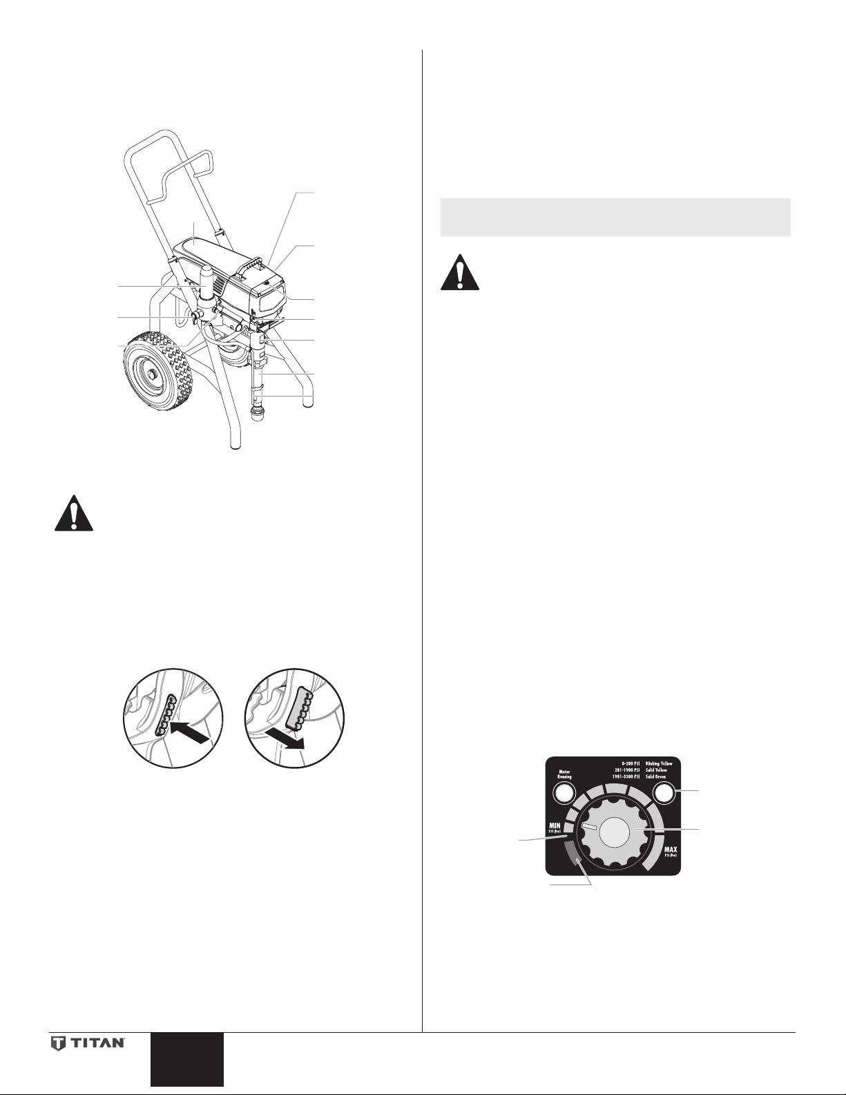
General Description
SPR
ac™ Screen
12
RapidClean
P
nob
This airless sprayer is a precision power tool used for spraying
many types of materials. Read and follow this instruction manual
carefully for proper operating instructions, maintenance, and safety
information.
Pressure
control knob
(reverse side)
Digi-Tr
(reverse side)
Oiler Cap
Oiler button
Fluid section
Siphon tube
Return tube
Filter
assembly
PRIME /
AY Valve
Outlet
tting
Motor
Operation
This equipment produces a fluid stream at extremely
high pressure. Read and understand the warnings
in the Safety Precautions section at the front of this
manual before operating this equipment.
Setup
Perform the following procedure before plugging in the power cord
of an electric unit.
1. Ensure that the siphon tube and the return hose are attached
and secure.
2. Using a wrench, attach a minimum of 50’ of 1/4” airless spray
hose to the outlet tting on the sprayer. Tighten securely.
3. Attach an airless spray gun to the spray hose. Using two
wrenches (one on the gun and one on the hose), tighten
securely.
NOTE: Do not attach the tip to the spray gun yet. Remove
the tip if it is already attached.
Make sure all airless hoses and spray guns are
electrically grounded and rated at or above the
maximum operating pressure range of the airless
sprayer.
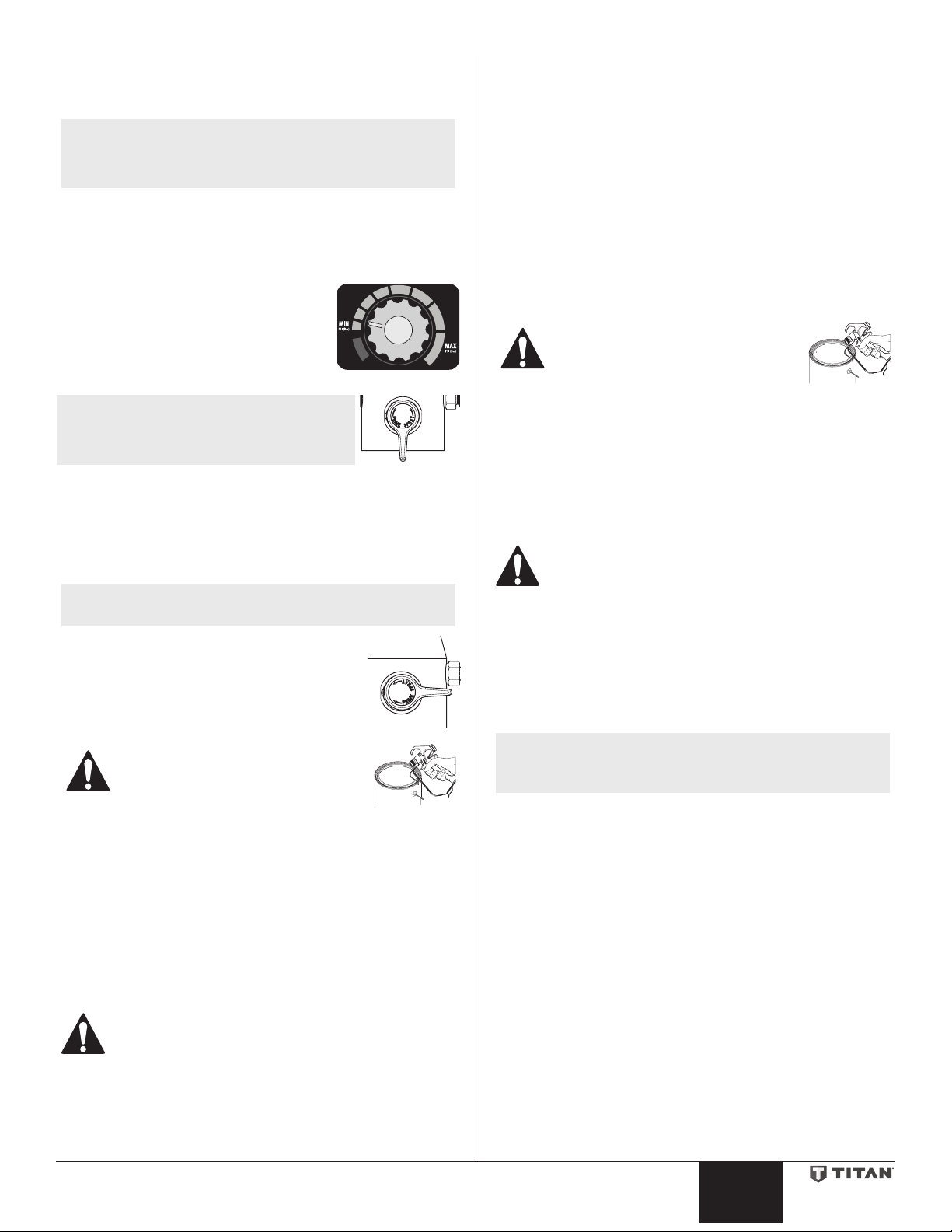
4. Make sure the pressure control knob is in its OFF position in
the black zone.
5. Make sure the ON/OFF switch is in its OFF position.
6. Remove the ll cap with a straight-slot screwdriver, or a coin.
Fill the oil reservoir with one ounce of piston seal lubricant
(Piston Lube). Replace oiler cap.
7. Press oiler button 2-5 times to prime the oiler. Press once for
every eight hours of usage to lubricate the uid section.
IMPORTANT: Never operate unit for more than ten seconds
without fluid. Operating this unit without fluid will cause
unnecessary wear to the packings.
8. Make sure the electrical service is 120V, 15 amp minimum.
9. Plug the power cord into a properly grounded outlet at least
25’ from the spray area.
IMPORTANT: Always use a minimum 12 gauge, three-wire
extension cord with a grounded plug. Never remove the third
prong or use an adapter.
Using the Gun Trigger Lock
Always engage the gun’s trigger lock when the gun is not in use.
1. To lock the trigger, push in the trigger lock from left to right,
when looking at the rear of the gun.
2. To unlock the trigger, push the trigger lock from right to left,
when looking at the rear of the gun.
Gun locked
(gun will not spray)
Gun unlocked
(gun will spray)
Preparing a New Sprayer
If this sprayer is new, it is shipped with test uid in the uid section to
prevent corrosion during shipment and storage. This uid must be
thoroughly cleaned out of the system with mineral spirits before you
begin spraying.
IMPORTANT: Always keep the trigger lock on the spray gun in
the locked position while preparing the system.
1. Place the siphon tube into a container of mineral spirits.
2. Place the return hose into a metal waste container.
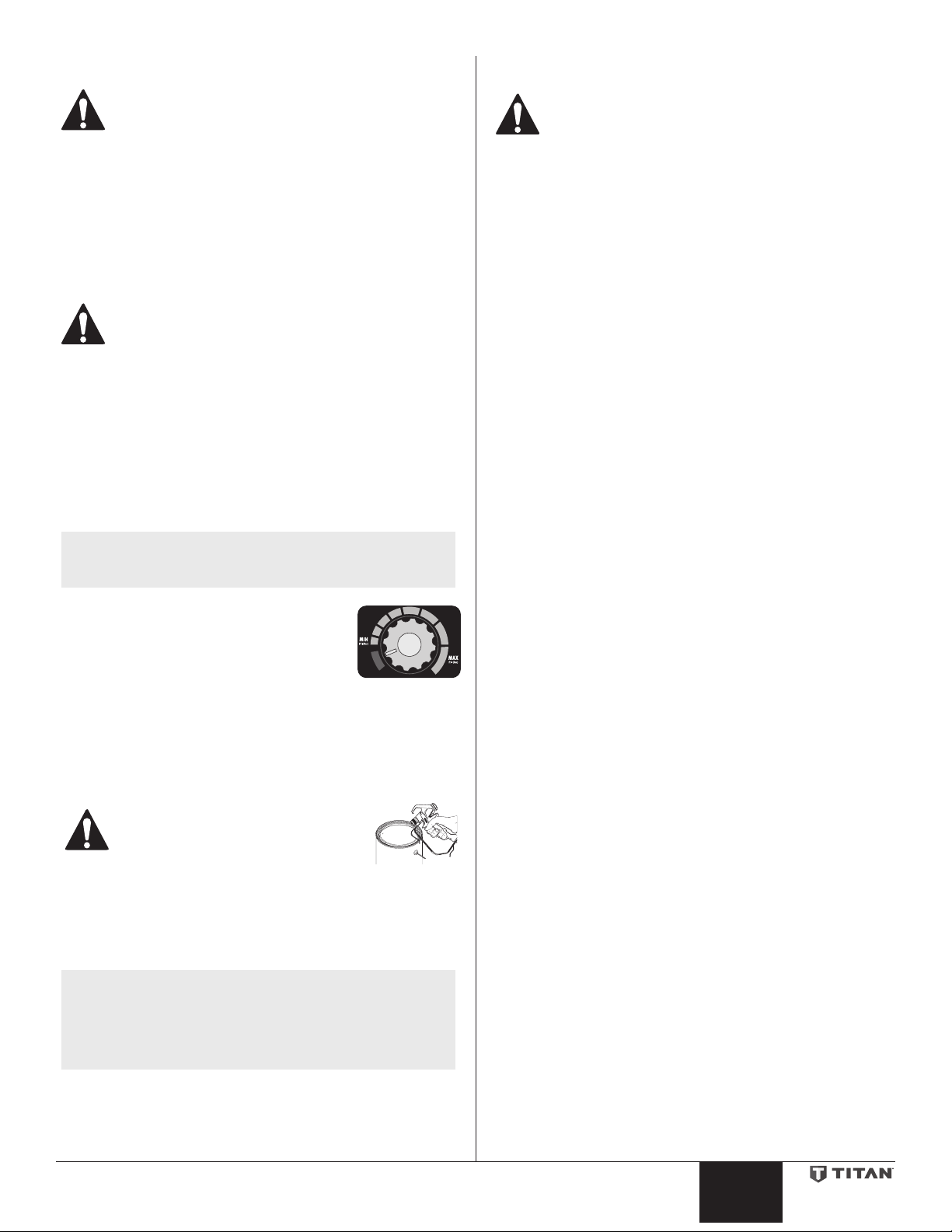
3. Set the pressure to minimum by turning the pressure control
knob to the “MIN” setting.
Pressure
Indicator
ump OFF
RAPID
CLEAN
4. Move the PRIME/SPRAY valve down to the PRIME position.
5. Turn on the sprayer by moving the ON/OFF switch to the ON
position.
6. Allow the sprayer to run for 15–30 seconds to ush the
test uid out through the return hose and into the waste
container.
7. Turn o the sprayer by moving the ON/OFF switch to the OFF
position.
Pressure
Control K
4 © Titan Tool Inc. All rights reserved.
English English
Page 5
Preparing to Paint
Before painting, it is important to make sure that the uid in the
system is compatible with the paint that is going to be used.
NOTE: Incompatible uids and paint may cause the valves
IMPORTANT: Always keep the trigger lock on the spray gun in
the locked position while preparing the system.
1. Place the siphon tube into a container of the appropriate
2. Place the return hose into a metal waste
3. Set the pressure to minimum by turning
4. Move the PRIME/SPRAY valve down to
NOTE: Hold the return hose in the waste
5. Turn on the sprayer by moving the ON/OFF switch to the ON
6. Allow the sprayer to run for 15–30 seconds to ush the old
7. Turn o the sprayer by moving the ON/OFF switch to the OFF
NOTE: Make sure that the spray gun does not have a tip or
8. Move the PRIME/SPRAY valve up to the SPRAY
9. Turn on the sprayer.
10. Unlock the gun by pushing the gun trigger
11. Trigger the gun into the metal waste container until the old
12. Lock the gun by pushing the gun trigger lock to the locked
13. Set down the gun and increase the pressure by turning the
14. Check the entire system for leaks. If leaks occur, follow the
15. Follow the “Pressure Relief Procedure” in this manual before
to become stuck closed, which would require
disassembly and cleaning of the sprayer’s uid
section.
solvent. Examples of the appropriate solvent are water for
latex paint or mineral spirits for oil-based paints.
container.
the pressure control knob to the “MIN”
setting.
the PRIME position.
container when moving the PRIME/
SPRAY valve to PRIME in case the
sprayer is pressurized.
position.
solvent out through the return hose and into the metal waste
container.
position.
tip guard installed.
position.
lock to the unlocked position.
Ground the gun by holding it against
the edge of the metal container while
flushing. Failure to do so may lead to
a static electric discharge, which may
cause a fire.
solvent is gone and fresh solvent is coming out of the gun.
position.
pressure control knob slowly clockwise.
“Pressure Relief Procedure” in this manual before tightening
any ttings or hoses.
changing from solvent to paint.
RAPID
CLEAN
2. Place the return hose into a metal waste container.
3. Set the pressure to minimum by turning the pressure control
knob to the “MIN” setting.
4. Move the PRIME/SPRAY valve down to the PRIME position.
5. Turn on the sprayer by moving the ON/OFF switch to the ON
position.
6. Allow the sprayer to run until paint is coming through the
return hose into the metal waste container.
7. Turn o the sprayer by moving the ON/OFF switch to the OFF
position.
8. Remove the return hose from the waste container and place it
in its operating position above the container of paint.
9. Move the PRIME/SPRAY valve up to the SPRAY position.
10. Turn on the sprayer.
11. Unlock the gun by pushing the gun trigger lock to the
unlocked position.
Ground the gun by holding it against
the edge of the metal container while
flushing. Failure to do so may lead to
a static electric discharge, which may
cause a fire.
12. Trigger the gun into the metal waste container until all air and
solvent is ushed from the spray hose and paint is owing
freely from the gun.
13. Lock the gun by pushing the gun trigger lock to the locked
position.
14. Turn o the sprayer.
15. Attach tip guard and tip to the gun as instructed by the tip
guard or tip manuals.
POSSIBLE INJECTION HAZARD. Do not spray without
the tip guard in place. Never trigger the gun unless
the tip is in either the spray or the unclog position.
Always engage the gun trigger lock before removing,
replacing or cleaning tip.
16. Turn on the sprayer.
17. Increase the pressure by turning the pressure control knob
slowly clockwise and test the spray pattern on a piece of
cardboard. Adjust the pressure control knob until the
spray from the gun is completely atomized. Try to keep the
pressure control knob at the lowest setting that maintains
good atomization.
NOTE: Turning the pressure up higher than needed to
atomize the paint will cause premature tip wear and
additional overspray.
Be sure to follow the pressure relief procedure when
shutting down the sprayer for any purpose, including
servicing or adjusting any part of the spray system,
changing or cleaning spray tips, or preparing for
cleanup.
Painting
1. Place the siphon tube into a container of paint.
© Titan Tool Inc. All rights reserved. 5
Page 6
Control Panel Indicators
r
Indicato
F
SET PSI 3000
ACTUAL PSI 2950
VOLUME PUMPED
SELECT-4MENU-1
GALLONS X
MENU-1
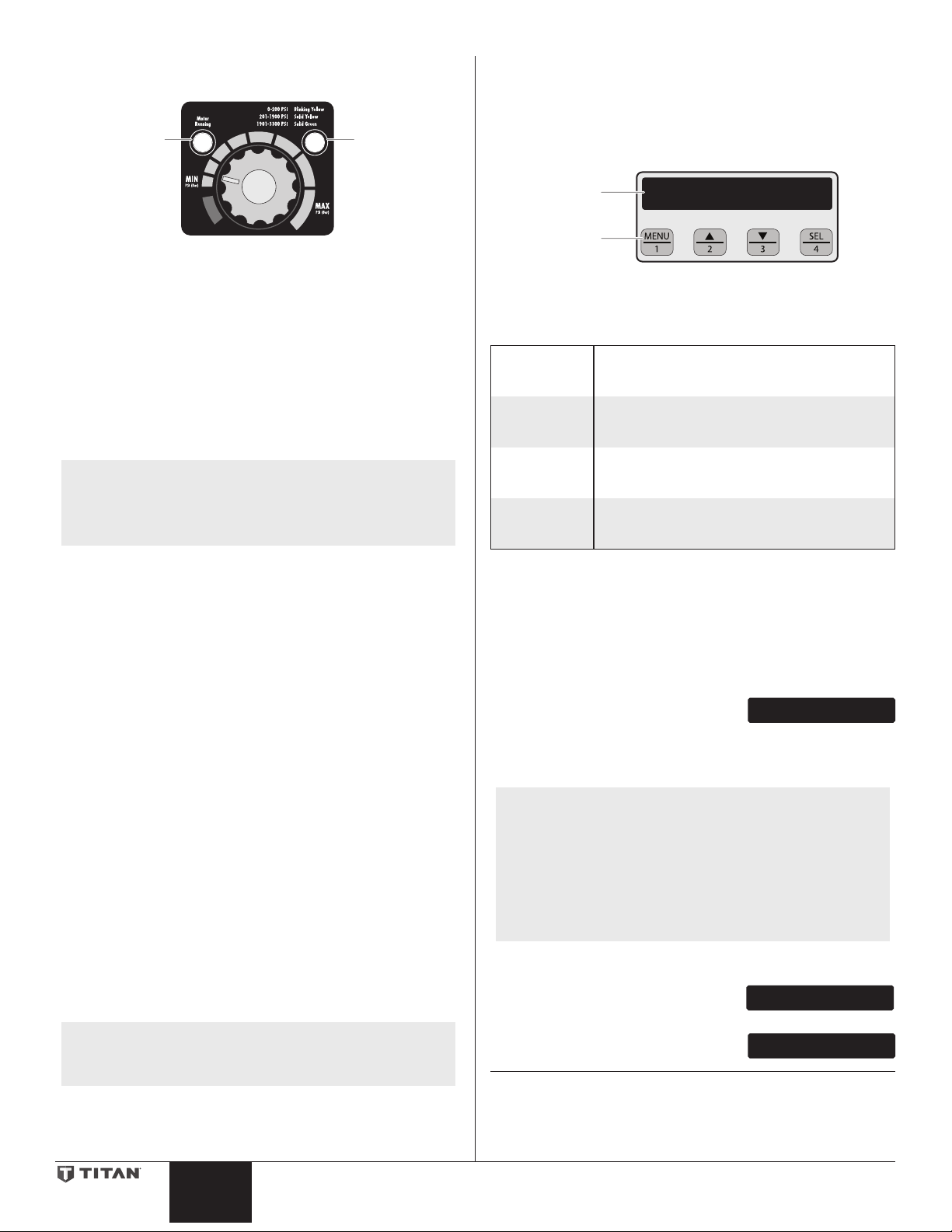
The following is a description of the control panel indicators.
Motor
Running
r
RAPID
CLEAN
Pressure
Indicato
Pressure Indicator
The pressure indicator shows the current operating pressure of the
sprayer. It has three dierent indications: blinking yellow, solid
yellow, and solid green.
Blinking Yellow
When the pressure indicator is blinking yellow, the sprayer is
operating between 0 and 200 PSI. A blinking yellow pressure
indicator means:
• The sprayer is plugged in and turned “ON”
• The sprayer is at priming pressure (little or no pressure)
• It is safe to move the PRIME/SPRAY valve between positions
• It is safe to change or replace the spray tip
NOTE: If the pressure indicator begins blinking yellow
when the pressure control knob is set at a higher
pressure and the PRIME/SPRAY valve is in the
SPRAY position, either the spray tip is worn or the
sprayer is in need of service/repair.
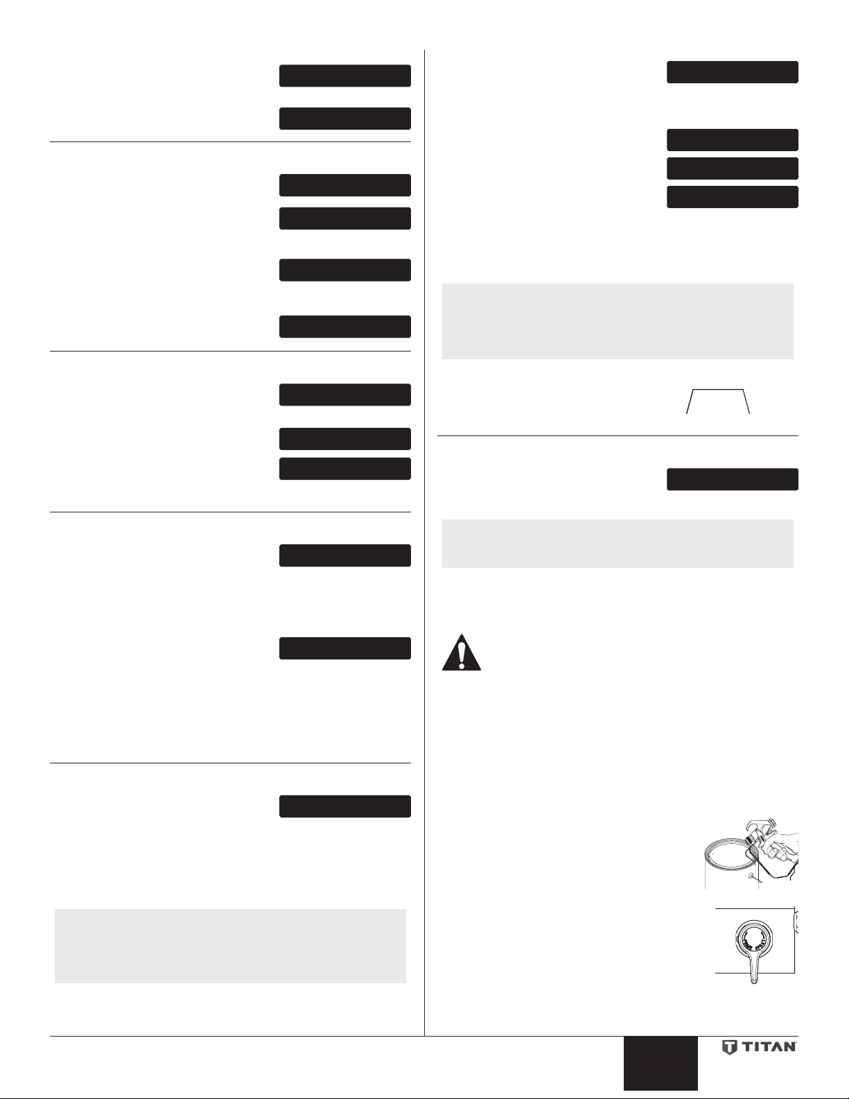
Digi-Trac™ Control System Operation
The Digi-Trac™ Control System is an optional add-on that increases
the functionality of the sprayer. It is installed directly below the
pressure control knob on the control panel. It consists of a display
and four function keys. The display shows various menu screens that
allow the user to customize and monitor sprayer operation using the
function keys.
Display
unction
Keys
Function Keys
The function keys are numbered 1–4. Each key is labeled with an
additional function as well.
#1/Menu Key Pressing the #1 key scrolls through the available
#2/p Key
#3/q Key
#4/Select Key Pressing the #4 key selects the active menu
menu screens or performs a function described
on the active menu screen.
Pressing the #2 key performs a function
described on the active menu screen or increases
a value.
Pressing the #3 key performs a function
described on the active menu screen or decrease
a value.
screen or performs a function described on the
active menu screen.
SET PSI 3000
ACTUAL PSI 2950
Solid Yellow
When the pressure indicator is solid yellow, the sprayer is operating
between 201 and 1900 PSI. A solid yellow pressure indicator means:
• The sprayer is at the proper pressure setting for spraying stain,
lacquer, varnish, and multi-colors
• If the pressure indicator goes to solid yellow when the
pressure is set so that it starts at solid green, it indicates one of
the following:
a. Tip Wear Indicator — when spraying with latex or at high
pressure the solid yellow appears. This means the tip is worn
and needs to be replaced.
b. Tip Too Large — when a tip that is too large for the sprayer is
put in the gun, the pressure indicator will turn from solid green
to solid yellow.
c. Fluid Section Wear — if a solid yellow pressure indicator
appears when using a new tip and the pressure is set at
maximum, service may be required (worn packings, worn
piston, stuck valve, etc...).
Solid Green
When the pressure indicator is solid green, the sprayer is operating
between 1901 and 3300 PSI. A solid green pressure indicator means:
• The sprayer is at the proper pressure setting for spraying oil-
based and latex house paints
• The sprayer is operating at peak performance at a high
pressure setting
Motor Running Indicator
The Motor Running indicator is on when the motor is commanded to
run. This indicator is used by service centers to troubleshoot motor
problems.
NOTE: If the motor running and pressure indicators blink
alternately, it means the motor has overheated. Turn
pump OFF and allow to cool.
Menu Screens
Several menu screens are available for the user to customize and
monitor sprayer operation. They include Main Screen, User PreSets, Volume Pumped, Job Volume, Unit Serial #, TImers, Job Timers,
Service Time, Security Code, Prime, and RAPID CLEAN.
Main Screen
The Main Screen is the default screen for
the control system at sprayer startup.
Pressing the #2 key switches between PSI, Bar, and MPa units of
measure. Press the #1 key to scroll through the remaining menu
screens.
NOTE: For sprayers with serial numbers “15xxx01001”
and higher, you are able to change the display text
language by following the below procedure.
Pressing the #3 key at the Main Screen changes
the language of the text on the display. There are
a total of nine languages available. Each time the
#1 key is pressed, a dierent language will appear.
The languages, in order of appearance, are: English,
Spanish, Dutch, Danish, Swedish, German, French,
Italian, and Portuguese.
Volume Pumped Screen
The Volume Pumped screen shows the
total number of gallons or liters sprayed
by the sprayer.
To select the Volume Pumped screen,
press the #4 key.
6 © Titan Tool Inc. All rights reserved.
English English
Page 7
Job Volume Screen
JOB VOLUME
SELECT-4MENU-1
JOB GAL XXXX
RESET-3MENU-1
UNIT SERIAL #
SELECT-4MENU-1
SER # XXXXXXXXXX
TIMERS
ON TIME
RUN TIME
XXXX
XXXX
JOB TIMERS
SELECT-4MENU-1
JOB ON X
SERVICE TIME
SERVICE @ XX
SECURITY CODE
ENTER OLD CODE
ENTER NEW CODE
RAPID CLEAN
The Job Volume screen allows the user to
reset a gallon counter to track usage on
specic jobs.
To select the Job Volume screen, press
the #4 key.
Unit Serial # Screen
The Unit Serial # screen shows the
sprayers serial number.
To select the Unit Serial # screen, press
the #4 key.
Timers Screen
The Timers screen shows the total time
the sprayer has been turned on as well
as the total time the sprayer has been
running (pumping).
To select the Timers screen, press the #4
key.
MENU-1
Enter the old security code number to
access the screen that allows the code
NUMBER XXXX
change. If the wrong code is entered, the
display will continue to ask for the correct
code and the security code cannot be changed.
Enter the new security code. Once the
new code is entered, the display will
automatically ask that the new code be
re-entered for verication. If the same
new code is re-entered, the display will
conrm that the new code has been
accepted and return to the Main Screen.
NUMBER XXXX
RE-ENTER NEW
NUMBER XXXX
NEW CODE NUMBER
ACCEPTED
If the new code is re-entered incorrectly, the display will return to the
“Enter New Code Number” screen and the process will repeat.
If you forget or misplace your security code, you can call Titan
SELECT-4MENU-1
customer service for assistance.
NOTE: To inactivate the Anti-Theft Digital Lockout security
function, enter “1111” at the “Enter New Code
Number” screen (this is the default code that leaves
the sprayer unlocked). As a result, the Main Screen
will appear at sprayer startup.
Job Timers Screen
The Job Timers screen allows the user to
reset the “ON TIME” and “RUN TIME” to
track time on specic jobs.
To select the Job TImers screen, press
the #4 key. “JOB ON” screen will appear.
Press #3 to reset. Press #1 to continue to
“JOB RUN” screen. Press #3 to reset. Press
JOB RUN X
RESET-3MENU-1
RESET-3MENU-1
#1 to scroll through the remaining menu
screens.
Service Time Screen
The Service Time screen allows the user
to set a service time interval (in hours).
Below the set time, the screens shows the
current amount of hours on the sprayer
since the last activation of the service
timer. To select the Service Timer screen,
press the #4 key.
To set the service time, press the #2 (up)
and/or the #3 (down) keys to the desired
RUN HOURS XX
time (run hours will increase/decrease in
increments of 25 for each time you press
a key).
When the sprayer reaches the SERVICE@ time selected, the screen will
display “SERVICE DUE”. To reset the timer, press the #3 key when the
pump is rst turned on. This will reset the “SERVICE DUE” message
and also reset the “SERVICE TIME” to the previous setting.
SELECT-4MENU-1
Security Code Screen
The Security Code screen allows the
user to set a four digit security code to
prevent unauthorized use of the sprayer. If a security code has been
set, the control system display will ask for the code at startup. If the
correct code is entered, the display will show the Main Screen and
the sprayer will operate. If the wrong code is entered, the display will
continue to ask for the correct code and the sprayer will not work. To
set or change the security code, press the #2 key.
NOTE: If the sprayer is new, no security code is set and the
Main Screen will appear at startup. When setting a
security code for the rst time, the “Enter Old Code
Number” screen will appear, and you will need to
enter “1111”.
CHANGE-2MENU-1
Prime Screen
The Prime screen appears when the
pressure control knob is set at the “MIN”
setting.
Rapid Clean Screen
The Rapid Clean screen appears when the
pressure control knob is set at the RAPID
CLEAN position and the PRIME/SPRAY valve is in the PRIME position.
NOTE: If there is no action at any menu screen for 30
seconds, the display will go back to the Main Screen.
Pressure Relief Procedure
Be sure to follow the pressure relief procedure when
shutting down the sprayer for any purpose, including
servicing or adjusting any part of the spray system,
changing or cleaning spray tips, or preparing for
cleanup.
1. Lock the gun by pushing the gun trigger lock to the locked
position.
2. Turn o the sprayer by moving the ON/OFF switch to the OFF
position.
3. Turn the pressure control knob counterclockwise to its OFF
position in the black zone.
4. Unlock the gun by pushing the gun trigger lock to the
unlocked position.
5. Hold the metal part of the gun rmly to
the side of a metal container to ground
the gun and avoid a build up of static
electricity.
6. Trigger the gun to remove any pressure
that may still be in the hose.
7. Lock the gun by pushing the gun trigger lock
to the locked position.
8. Move the PRIME/SPRAY valve down to the
PRIME position.
© Titan Tool Inc. All rights reserved. 7
Page 8
Spraying
Arcing Gun at angle
POSSIBLE INJECTION HAZARD. Do not spray without
the tip guard in place. Never trigger the gun unless
the tip is in either the spray or the unclog position.
Always engage the gun trigger lock before removing,
replacing, or cleaning tip.
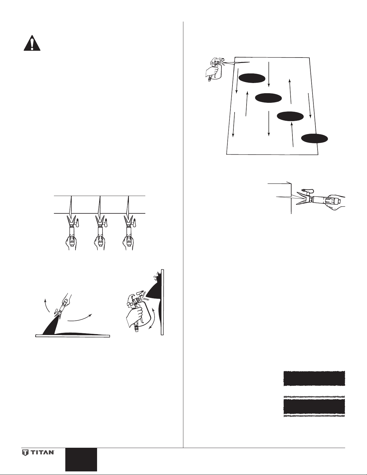
Spraying Technique
The following techniques, if followed, will assure professional
painting results.
Hold the gun perpendicular to the surface and always at equal
distance from the surface. Depending on the type of material,
surface, or desired spray pattern, the gun should be held at a distance
of 12 to 14 inches (30 to 35 cm).
Move the gun either across or up and down the surface at a steady
rate. Moving the gun at a consistent speed conserves material and
provides even coverage. The correct spraying speed allows a full, wet
coat of paint to be applied without runs or sags.
Holding the gun closer to the surface deposits more paint on the
surface and produces a narrower spray pattern. Holding the gun
farther from the surface produces a thinner coat and wider spray
pattern. If runs, sags, or excessive paint occur, change to a spray tip
with a smaller orice. If there is an insucient amount of paint on
the surface or you desire to spray faster, a larger orice tip should be
selected.
Maintain uniform spray stroke action. Spray alternately from left to
right and right to left. Begin movement of the gun before the trigger
is pulled.
start
stroke
Avoid arcing or holding the gun at an angle. This will result in an
uneven nish.
pull
trigger
release
trigger
end
stroke
Ospray
Proper lapping (overlap of spray pattern) is essential to an even nish.
Lap each stroke. If you are spraying horizontally, aim at the bottom
edge of the preceding stroke, so as to lap the previous pattern by
50%.
Overlap edges
1st
pass
For corners and edges, split the
center of the spray pattern on the
corner or edge and spray vertically
so that both adjoining sections
receive approximately even
amounts of paint.
When spraying with a shield, hold
it rmly against the surface. Angle the spray gun slightly away from
the shield and toward the surface. This will prevent paint from being
forced underneath.
Shrubs next to houses should be tied back and covered with a canvas
cloth. The cloth should be removed as soon as possible. Titan gun
extensions are extremely helpful in these situations.
Nearby objects such as automobiles, outdoor furniture, etc. should
be moved or covered whenever in the vicinity of a spray job. Be
careful of any other surrounding objects that could be damaged by
overspray.
2nd
pass
3rd
pass
4th
pass
5th
pass
Practice
1. Make sure that the paint hose is free of kinks and clear of
objects with sharp cutting edges.
3. Set the pressure to minimum by turning the pressure control
knob to the “Min” setting in the yellow zone.
Too Thick
8 © Titan Tool Inc. All rights reserved.
English English
3. Move the PRIME/SPRAY valve up to its SPRAY position.
4. Turn the pressure control knob clockwise to its highest setting
in the green zone. The paint hose should stien as paint
begins to ow through it.
5. Unlock the gun trigger lock.
6. Trigger the spray gun to bleed air out of the hose.
7. When paint reaches the spray tip, spray a test area to check
the spray pattern.
8. Use the lowest pressure setting
necessary to get a good spray
pattern. If the pressure is set too
high, the spray pattern will be
too light. If the pressure is set
too low, tailing will appear or
the paint will spatter out in gobs
rather than in a ne spray.
Good spray pattern
Paint tailing pattern
Page 9
Cleanup
Maintenance
Special cleanup instructions for use with flammable
solvents:
• Always ush spray gun preferably outside and at least one
hose length from spray pump.
• If collecting ushed solvents in a one gallon metal container,
place it into an empty ve gallon container, then ush solvents.
• Area must be free of ammable vapors.
• Follow all cleanup instructions.
IMPORTANT: The sprayer, hose, and gun should be cleaned
thoroughly after daily use. Failure to do so permits material to
build up, seriously affecting the performance of the unit.
Always spray at minimum pressure with the gun
nozzle tip removed when using mineral spirits or any
other solvent to clean the sprayer, hose, or gun. Static
electricity buildup may result in a fire or explosion in
the presence of flammable vapors.
1. Follow the “Pressure Relief Procedure” found in the Operation
section of this manual.
2. Remove the gun tip and tip guard and clean with a brush
using the appropriate solvent.
3. Place the siphon tube into a container of the appropriate
solvent. Examples of the appropriate solvent are water for
latex paint or mineral spirits for oil-based paints.
4. Place the return hose into a metal waste container.
5. Move the PRIME/SPRAY valve down to its PRIME position.
NOTE: Hold the return hose in the waste container when
6. Set the pressure to RAPID CLEAN by turning
7. Turn on the sprayer by moving the ON/OFF
8. Allow the solvent to circulate through the
9. Turn o the sprayer by moving the ON/OFF switch to the OFF
10. Move the PRIME/SPRAY valve up to its SPRAY position.
11. Turn on the sprayer.
moving the PRIME/SPRAY valve to PRIME in case the
sprayer is pressurized.
the pressure control knob to its RAPID
CLEAN position.
RAPID
switch to the ON position.
unit and ush the paint out of the return hose into the metal
waste container.
position.
CLEAN
Before proceeding, follow the Pressure Relief
Procedure outlined previously in this manual.
Additionally, follow all other warnings to reduce the
risk of an injection injury, injury from moving parts
or electric shock. Always unplug the sprayer before
servicing!
General Repair and Service Notes
The following tools are needed when repairing this sprayer:
Phillips Screwdriver 3/8” Hex Wrench
Needle Nose Pliers 5/16” Hex Wrench
Adjustable Wrench 1/4” Hex Wrench
Rubber Mallet 3/16” Hex Wrench
Flat-blade Screwdriver 5/32” Hex Wrench
5/64” Hex Wrench
1. Before repairing any part of the sprayer, read the instructions
carefully, including all warnings.
IMPORTANT: Never pull on a wire to disconnect it. Pulling on a
wire could loosen the connector from the wire.
2. Test your repair before regular operation of the sprayer to be
sure that the problem is corrected. If the sprayer does not
operate properly, review the repair procedure to determine if
everything was done correctly. Refer to the Troubleshooting
Charts to help identify other possible problems.
3. Make certain that the service area is well ventilated in case
solvents are used during cleaning. Always wear protective
eyewear while servicing. Additional protective equipment
may be required depending on the type of cleaning solvent.
Always contact the supplier of solvents for recommendations.
4. If you have any further questions concerning your Titan Airless
Sprayer, call Titan:
Customer Service ................................................ 1-800-526-5362
Fax ................................................................. 1-800-528-4826
Ground the gun by holding it against
the edge of the metal container while
flushing. Failure to do so may lead to
a static electric discharge, which may
cause a fire.
12. Trigger the gun into the metal waste container until the paint
is ushed out of the hose and solvent is coming out of the
gun.
13. Continue to trigger the spray gun into the waste container
until the solvent coming out of the gun is clean.
NOTE: For long-term or cold weather storage, pump
mineral sprits through the entire system.
For short-term storage when using latex paint,
pump water mixed with Titan Liquid Shield through
the entire system (see the Accessories section of this
manual for part number).
14. Follow the “Pressure Relief Procedure” found in the Operation
section of this manual.
15. Unplug the unit and store in a clean, dry area.
IMPORTANT: Do not store the unit under pressure.
© Titan Tool Inc. All rights reserved. 9
Page 10
Replacing the Filters
Handle
Gearbox
Control
Pump Filter
1. Loosen and remove the lter
body by hand.
2. Slip the lter o of the core
spring.
3. Inspect the lter. Based on
inspection, clean or replace the
lter.
4. Inspect the o-ring. Based on
inspection, clean or replace the
o-ring.
5. Slide the new or cleaned lter
over the core spring with the
lter spring adapter in place.
Push the lter into the center of
the lter housing.
6. Slide the lter body over the
lter and thread it into the lter
housing until secure.
NOTE: The lter housing
should be handtightened, but make
sure the lter housing
is seated fully into the
pump block.
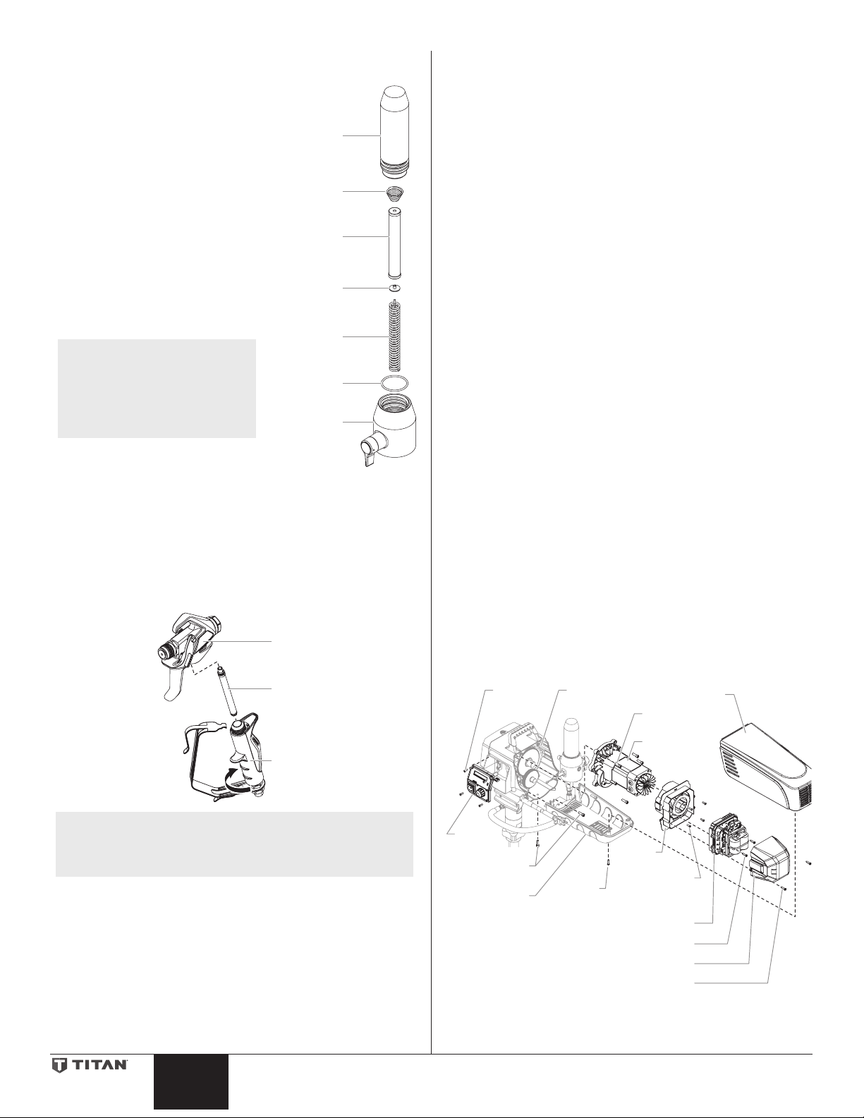
Gun Filter
1. Unclip the top of the trigger guard from the gun body.
2. Using the bottom of the trigger guard as a wrench, loosen and
remove the handle assembly from the gun head.
3. Pull the old lter out of the gun body. Clean or replace.
4. Slide the new lter, tapered end rst, into the gun head.
5. Thread the handle assembly into the gun head. Tighten with
the trigger wrench.
6. Snap the trigger guard back onto the gun body.
Filter Body
Filter Spring
Filter
Filter Spring
Adapter
Core Spring
O-ring
Filter Housing
Gun
Body
Replacing the Motor Assembly
1. Unplug the unit.
2. Loosen and remove the two (2) motor shroud screws. Remove
the motor shroud.
3. Loosen and remove the three (3) belly pan screws. Remove
the belly pan.
4. Loosen and remove the two (2) motor cover screws. Remove
the motor cover.
5. Disconnect all wires between the motor and the sprayer.
6. Loosen and remove the four (4) control panel screws. Remove
the control panel.
7. Disconnect the wires between the motor and the control
panel.
8. Loosen and remove the two (2) motor controller screws.
Remove the motor controller.
9. Loosen and remove the four (4) motor bae screws. Remove
the motor bae.
10. Loosen and remove the six (6) motor mounting screws.
11. Pull the motor out of the gearbox housing.
12. With the motor removed, inspect the gears in the gearbox
housing for damage or excessive wear. Replace the gears, if
necessary.
13. Install the new motor into the gearbox housing.
14. Secure the motor with the six (6) motor mounting screws.
15. Reconnect the wires between the sprayer and the new motor.
(refer to the electrical schematic in the Parts List section of this
manual).
16. Place the bae over the end of the motor assembly. Secure
with the four (4) motor bae screws.
17. Place motor controller back into place behind the motor
bae. Secure with the two (2) motor controller screws.
18. Reconnect all wires between the motor and sprayer.
19. Reconnect the wires between the motor and the control
panel.
20. Replace control panel and secure with four (4) control panel
screws.
21. Place the motor cover back over the motor controller. Secure
with the two (2) motor cover screws.
22. Put the belly pan back in place and secure with the three (3)
belly pan screws.
23. Slide the motor shroud over the motor assembly.
24. Secure the motor shroud with the two (2) motor shroud
screws.
Filter
Panel
Screw
NOTE: For more detail, part number information, and
10 © Titan Tool Inc. All rights reserved.
complete assembly drawings, please see the RX-Pro
Airless Gun Owner’s Manual.
English English
Control
Panel
Belly Pan
Belly Pan
Screw
housing
Motor
Shroud
Screw
Motor Controller
Motor Controller Screw
Motor Cover Screw
Motor Shroud
Motor Mounting
Screw
Motor
Motor
Bae
Motor Bae
Screw
Motor Cover
Page 11
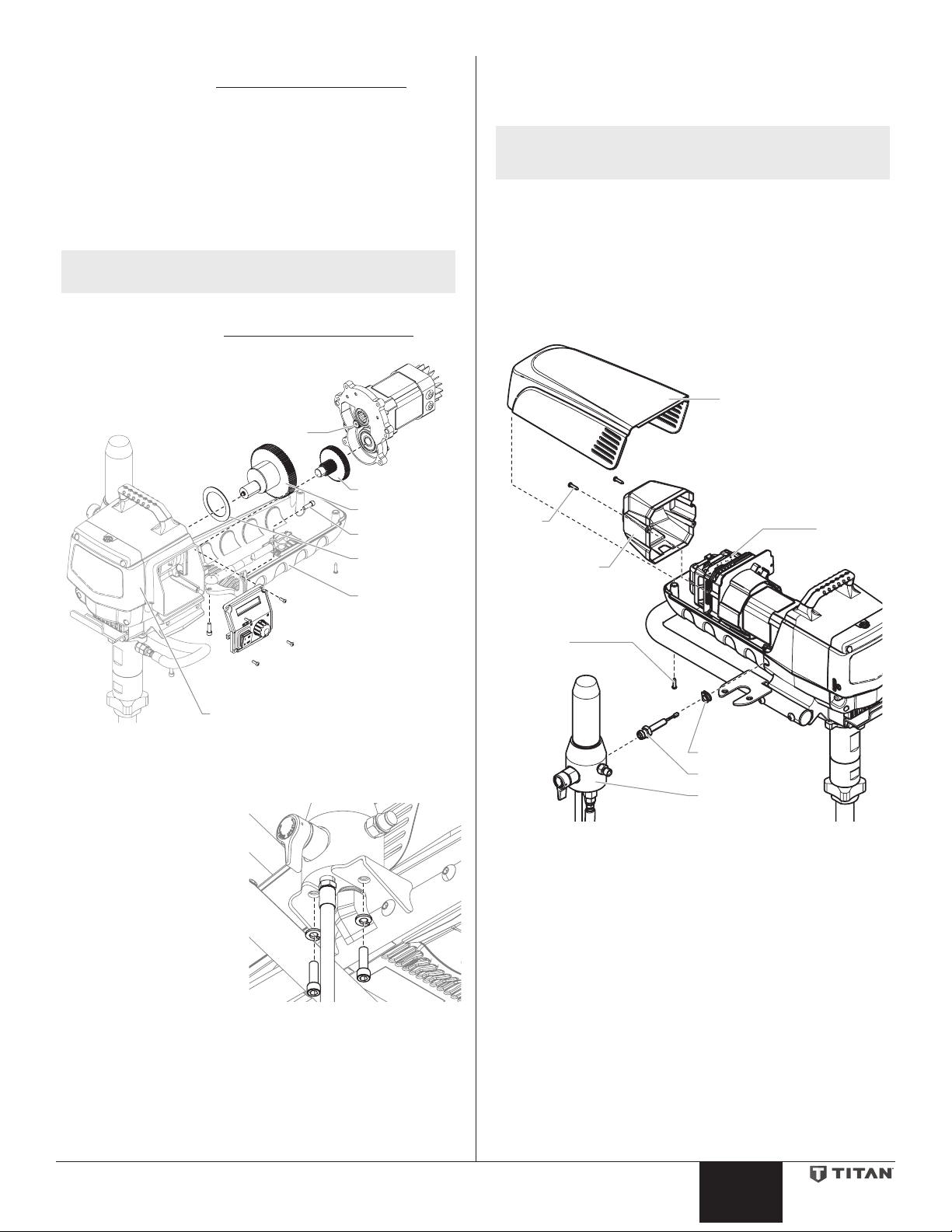
Replacing the Gears
2nd Stage Gear
w
Front Gear Box Assembly
Mo
1. Follow steps 1-11 in Replacing the Motor Assembly (page
10) to remove the motor and control panel.
2. Inspect the armature gear on the end of the motor for damage
or excessive wear. If the gear is completely worn out, replace
the motor assembly.
3. Remove and inspect the 1st stage gear and 2nd stage
gear assemblies for damage or excessive wear. Replace, if
necessary.
4. Inspect the front gear box assembly for damage or excessive
wear. If damaged or worn, replace the front gear box
assembly.
NOTE: Clean and rell the gear box cavity up to the rear
face of each gear with Lubriplate (P/N 314-171).
5. Reinstall the motor into the gearbox housing.
6. Follow steps 13-24 in Replacing the Motor Assembly (page
10) to replace the motor and control panel.
Armature Gear
1st Stage Gear
9. Thread the new transducer wire through the mounting plate
and back to the motor controller.
10. Thread the new transducer into the lter housing and tighten
securely with a wrench.
NOTE: Make sure the o-ring on the transducer is in place
before threading the transducer into the lter
housing.
11. Push the grommet into the mounting plate.
12. Connect the transducer wire to the motor controller (refer
to the electrical schematic in the Parts List section of this
manual).
13. Place the motor cover back over the motor controller. Secure
with the two (2) motor cover screws.
14. Slide the motor shroud over the motor assembly.
15. Secure the motor shroud with the two (2) motor shroud
screws.
Motor Shroud
Belly Pan Scre
Thrust Washer
Belly Pan
Replacing the Transducer
1. Unplug the unit.
2. Loosen and remove the
two (2) lter assembly
bolts. Slide the lter
assembly from the cart.
3. Loosen and remove the
two (2) motor shroud
screws. Remove the
motor shroud.
4. Loosen and remove
the two (2) motor cover
screws. Remove the
motor cover.
5. Disconnect the
transducer wire from the
motor controller.
6. Pull the grommet out of the mounting plate and slide it up the
shaft of the transducer until it is clear of the mounting plate.
7. Using a wrench, loosen and remove the transducer from
the lter housing. Carefully thread the transducer wire out
through the mounting plate.
8. Slide the grommet o of the old transducer and onto the new
transducer.
tor
Cover
Screw
Shroud
Motor
Controller
Motor
Cover
Motor
Screw
Grommit
Tranducer
Filter assembly
© Titan Tool Inc. All rights reserved. 11
Page 12
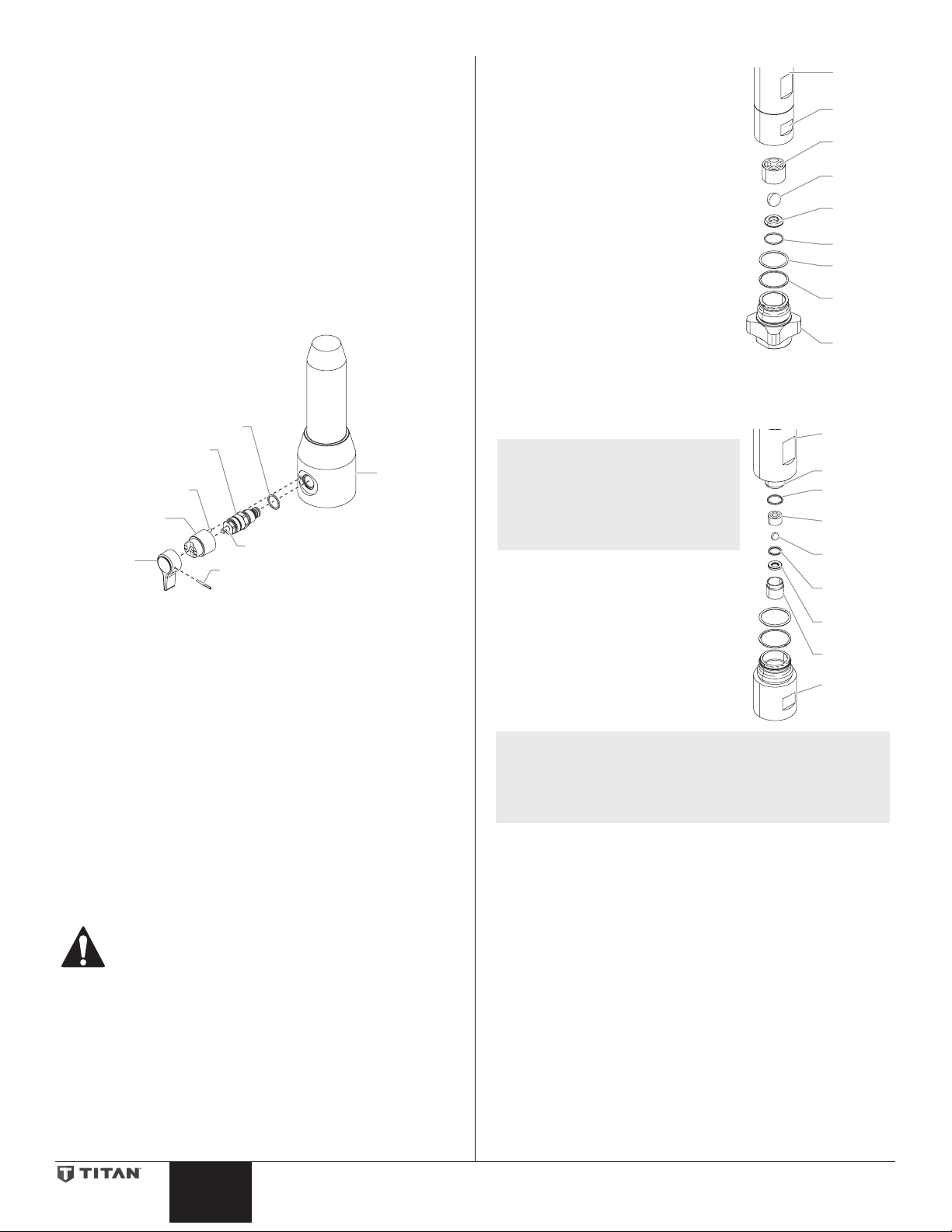
Replacing the PRIME/SPRAY Valve
Housing
Handle
e
e
e
e
Upper
e
e
e
e
e
Upper
Perform the following procedure using PRIME/SPRAY valve
replacement kit P/N 700-248.
1. Push the groove pin out of the valve handle.
2. Remove the valve handle and the cam base.
3. Using a wrench, loosen and remove the valve housing
assembly.
4. Make sure the gasket is in place and thread the new valve
housing assembly into the lter block. Tighten securely with a
wrench.
5. Place the cam base over the valve housing assembly.
Lubricate the cam base with grease and line up the cam with
the lter block using the dowel pin.
6. Line up the hole on the valve stem with the hole in the valve
handle.
7. Insert the groove pin into the valve handle and through the
valve stem to secure the valve handle in position.
Gasket
Valve Housing
Dowel Pin
Cam Base
Valve
Assembly
Valve Stem
Groove Pin
Filter
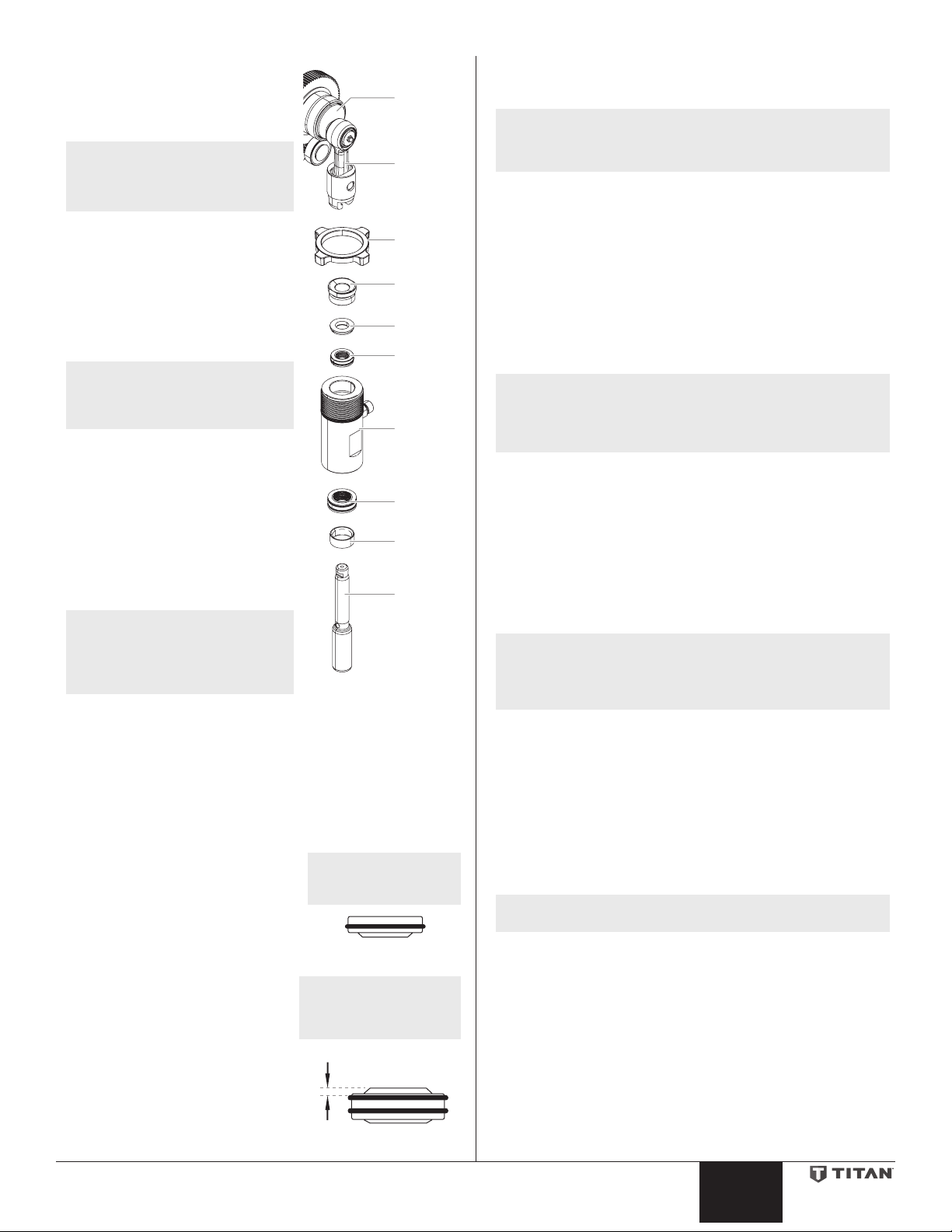
Servicing the Fluid Section
Use the following procedures to service the valves and repack the
uid section. Perform the following steps before performing any
maintenance on the uid section.
1. Loosen and remove the four front cover screws. Remove the
front cover.
2. Set the pressure to minimum by turning the pressure control
knob to the “MIN” setting. The Digi-Trac™ screen should say
“PRIME”.
3. Press the #1 key on the Digi-Trac™ control panel. The “CREEP
MODE” screen will now appear.
4. Slowly turn the pressure control knob clockwise to increase
the pressure. The crankshaft/slider assembly will begin to
move very slowly.
5. When it reaches the bottom, dead-center of its stroke, turn
the pressure control knob back to the “MIN” setting. The
crankshaft/slider assembly should stop.
6. Turn the pump o and unplug the unit.
Servicing the Valves
The design of the uid section allows
access to the foot valve and seat as well
as the outlet valve and seat without
completely disassembling the uid
section. It is possible that the valves may
not seat properly because of debris stuck
in the foot valve seat or outlet valve seat.
Use the following instructions to clean
the valves and reverse or replace the
seats.
1. Loosen and remove the foot valve
housing from the lower housing.
2. Clean out any debris in the foot
valve housing and examine the
housing and the foot valve seat.
If the seat is damaged, reverse or
replace the seat.
3. Using two wrenches, hold the
upper housing at the wrench ats
with one wrench and loosen the
lower housing with the other. Remove the lower housing.
4. Using a 3/8” wrench, loosen and remove the outlet valve
retainer from the piston rod.
NOTE: Always service the outlet
valve with the piston rod
attached to the pump. This
will prevent the piston
rod from rotating during
disassembly of the outlet
valve.
5. Clean out any debris and examine
the retainer and outlet valve seat.
If the seat is damaged, reverse or
replace the seat.
6. Remove, clean, and inspect the
outlet valve cage and outlet valve
ball. Replace if they are worn or
damaged.
7. Reassemble the valves by reversing
the steps above.
NOTE: During reassembly, make sure the Viton o-rings and
the PTFE back-up rings between the upper housing
and lower housing as well as between the lower
housing and the foot valve housing are lubricated
with grease and in position.
Housing
Lower
Housing
Foot Valv
Cage
Foot Valv
Ball
Foot Valv
Seat
O-ring
Viton
O-Ring
PTFE
Back-Up
Ring
Foot Valv
Housing
Housing
Piston Rod
Outlet Valv
Seal
Outlet Valv
Cage
Outlet Valv
Ball
Nylon
Washer
Outlet Valv
Seat
Outlet Valv
Retainer
Lower
Housing
Before proceeding, follow the Pressure Relief
Procedure outlined previously in this manual.
Additionally, follow all other warnings to reduce the
risk of an injection injury, injury from moving parts
or electric shock. Always unplug the sprayer before
servicing!
7. Remove the return hose from the clamp on the siphon tube.
8. Unscrew the siphon tube/siphon set from the foot valve.
9. Loosen and remove the high-pressure hose from the nipple
12 © Titan Tool Inc. All rights reserved.
on the back of the upper housing of the uid section.
English English
Page 13
Repacking the Fluid Section
t
Upper Seal
1. Remove the foot valve assembly
and the lower housing using the
steps in the “Servicing the Valves”
Crankshaf
procedure above.
NOTE: The outlet valve does not
need to be disassembled
from the piston rod for
Slider
Assembly
this procedure.
2. Tap the knock-o nut with a
soft hammer so that it turns
counterclockwise and loosens.
Knock-O
Nut
3. Turn the uid section
counterclockwise to remove it
from the gear box housing.
Retainer
4. Place the upper housing upright in
a vise by clamping on the wrench
Spacer
ats.
Upper
NOTE: Do not over-tighten
Packing
the vise. Damage to
the upper housing may
occur.
5. Using a wrench, remove the upper
Upper
Housing
seal retainer.
6. Slide the piston rod forward until
the piston is out of the T-slot on
the slider assembly.
7. Pull the piston out through the
bottom of the upper housing.
8. Inspect the piston rod for wear and
Lower
Packing
Wear Ring
replace if necessary.
9. Remove the upper and lower
packings from the upper housing.
Piston Rod
NOTE: Be careful not to scratch,
score, or otherwise
damage the upper
housing during removal
of the packings.
10. Clean the upper housing. Inspect the upper housing for
damage and replace if necessary.
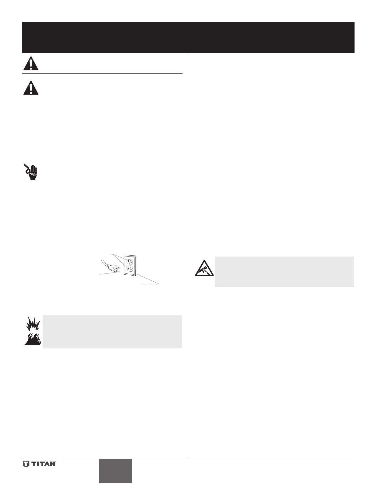
11. Remove the plastic wrap from the upper packing and preform tool.
IMPORTANT: Cut the plastic wrap with a scissors. Do not cut
plastic wrap with a utility knife as damage can occur to the
O-rings.
12. Slide the upper packing o the sizing/ insertion tool (towards
the tip) and install into the top of the upper housing with the
raised lip on the packing facing down.
13. Insert the spacer on top of the
upper packing.
14. Thread the upper seal retainer into
Install upper packing
with raised lip
facing down.
the upper housing and torque to
25-30 ft. lbs.
15. Pre-form the lower packing using
the lower packing sizing tool
Raised Lip
(included in the repacking kit).
16. Insert the lower packing partially
into the bottom of the upper
housing so that the side that has
the o-ring closest to the face of
Install lower packing with
the side that has the o-ring
closest to the face of the
packing facing up.
the packing faces up.
17. Push the lower packing into
position using the lower packing
insertion tool (see Fluid Section
Closer
Top
Assembly parts list for lower
packing insertion tool P/N).
18. Place the piston insertion tool
(included in the repacking kit) over the top of the piston rod.
19. Insert the piston rod into the bottom of the upper housing,
through the lower packing, through the upper packing, and
out through the upper seal retainer.
NOTE: When repacking the uid section, make sure the
raised lip on the bottom of the lower packing is fully
outside the packing around the piston rod after
insertion of the piston rod.
20. Remove the piston insertion tool from the top of the piston
rod.
21. Slide the top of the piston rod into the T-slot on the slider
assembly.
22. Turn the knock-o nut counterclockwise until it is ush
against the upper housing.
23. Lubricate the threads on the upper housing with anti-seize
compound. Remove the upper housing from the vise.
24. Thread the upper housing into the gear box housing, turning
clockwise.
25. Continue to turn the upper housing clockwise until the knocko nut is ush against the gear box housing.
NOTE: If the nipple on the upper housing does not face
the back of the unit, turn the upper housing
counterclockwise until the nipple faces the back of
the unit. Do not turn the upper housing more than
one full turn.
26. Once the nipple is positioned, turn the knock-o nut
clockwise until it contacts the gear box housing.
27. Tap the knock-o nut with a soft hammer to tighten it against
the gear box housing.
28. Making sure that the Viton o-ring and PTFE back-up ring are
lubricated and in place, thread the lower housing into the
upper housing. Using two wrenches, hold the upper housing
at the wrench ats with one wrench and tighten the lower
housing with the other.
29. Attach the high-pressure hose to the nipple on the back of the
housing and tighten with a wrench. Do not kink the hose.
NOTE: For low rider units, make sure the hose does not
touch the cart frame. If it does, reposition the nipple
by turning the upper housing until the hose is clear
of the frame and the nipple is within 45º of the back
of the unit.
30. Making sure that the Viton o-ring and PTFE back-up ring are
lubricated and in place, reassemble the foot valve assembly
and and thread it into the lower housing. Tighten securely.
31. Thread the siphon tube/siphon set into the foot valve and
tighten securely. Make sure to wrap the threads on the down
tube/siphon tube adapter with PTFE tape before assembly.
32. Replace the return hose into the clamp on the siphon tube.
33. Place the front cover on the gearbox housing and secure in
position using the four front cover screws.
34. Turn on the sprayer by following the procedure in the
“Operation” section of this manual and check for leaks.
NOTE: Repacking kit P/N 805-1010 is available. For best
results use all parts supplied in this kit.
© Titan Tool Inc. All rights reserved. 13
Page 14

Troubleshooting
Problem
A. The unit will not run.
B. The unit will not prime.
C. The unit will not build or
maintain pressure.
D. Fluid leakage at the upper end
of the uid section.
E. Excessive surge at the spray
gun.
F. Poor spray pattern.
G. The unit lacks power.
Cause
1. The unit is not plugged in.
2. Tripped breaker.
3. The pressure is set too low (pressure control
knob set at minimum setting does not supply
power to unit).
4. Faulty or loose wiring.
5. Excessive motor temperature.
6. ON/OFF switch is defective.
1. The PRIME/SPRAY valve is in the SPRAY
position.
2. Air leak in the siphon tube/siphon assembly.
3. The pump lter and/or inlet screen is clogged.
4. The siphon tube/siphon assembly is clogged.
1. The spray tip is worn.
2. The spray tip is too large.
3. The pressure control knob is not set properly.
4. The pump lter, gun lter, or inlet screen is
clogged.
5. Material ows from the return hose when the
PRIME/SPRAY valve is in the SPRAY position.
6. Air leak in the siphon tube/siphon assembly.
7. There is external uid leak.
8. There is an internal uid section leak
(packings are worn and/or dirty, valve balls
are worn).
9. Worn valve seats
10. Motor powers but fails to rotate
1. The upper packings are worn.
2. The piston rod is worn.
1. Wrong type of airless spray hose.
2. The spray tip worn or too large.
3. Excessive pressure.
1. The spray tip is too large for the material
being used.
2. Incorrect pressure setting.
3. Insucient uid delivery.
4. The material being sprayed is too viscous.
1. The pressure adjustment is too low.
2. Improper voltage supply.
Solution
1. Plug the unit in.
2. Reset the breaker.
3. Turn the pressure control knob clockwise to supply
power to the unit and increase the pressure setting.
4. Inspect or take to a Titan authorized service center.
5. Allow motor to cool.
6. Replace the ON/OFF switch.
1. Rotate the PRIME/SPRAY valve clockwise to the PRIME
position.
2. Check the siphon tube/siphon assembly connection and
tighten or re-tape the connection with PTFE tape.
3. Remove the pump lter element and clean. Remove the
inlet screen and clean.
4. Remove the siphon tube/siphon assembly and clean.
1. Replace the spray tip following the instructions that
came with the spray gun.
2. Replace the spray tip with a tip that has a smaller orice
following the instructions that came with the spray gun.
3. Turn the pressure control knob clockwise to increase the
pressure setting.
4. Remove the pump lter element and clean. Remove the
gun lter and clean. Remove the inlet screen and clean.
5. Clean or replace the PRIME/SPRAY valve.
6. Check the siphon tube/siphon assembly connection and
tighten or re-tape the connection with PTFE tape.
7. Check for external leaks at all connections. Tighten
connections, if necessary.
8. Clean the valves and service the uid section following
the “Servicing the Fluid Section” procedure in the
Maintenance section of this manual.
9. Reverse or replace the valve seats following the
“Servicing the Fluid Section” procedure in the
Maintenance section of this manual.
10. Take unit to a Titan authorized service center.
1. Repack the pump following the “Servicing the Fluid
Section” procedure in the Maintenance section of this
manual.
2. Replace the piston rod following the “Servicing the Fluid
Section” procedure in the Maintenance section of this
manual.
1. Replace hose with a minimum of 50’ of 1/4” grounded
textile braid airless paint spray hose.
2. Replace the spray tip following the instructions that
came with the spray gun.
3. Rotate the pressure control knob counterclockwise to
decrease spray pressure.
1. Replace the spray tip with a new or smaller spray tip
following the instructions that came with the spray gun.
2. Rotate the pressure control knob to adjust the pressure
for a proper spray pattern.
3. Clean all screens and lters.
4. Add solvent to the material according to the
manufacturer’s recommendations.
1. Rotate the pressure control knob clockwise to increase
the pressure setting.
2. Reconnect the input voltage for 120V AC.
14 © Titan Tool Inc. All rights reserved.
English English
Page 15

Digi-Trac™ Control System Error Messages
CHECK TRANSDUCER
CHECK
LOW VOLTAGE
HIGH MOTOR
HIGH MECHANICAL
HIGH CONTROL
CHECK MOTOR
BAD HALL CYCLE
The following error message screens appear whenever the Digi-Trac
Control System detects a problem with the sprayer. Once a problem
occurs and the error message appears, the sprayer will shut down.
Before proceeding, follow the Pressure Relief
Procedure outlined previously in this manual.
Additionally, follow all other warnings to reduce the
risk of an injection injury, injury from moving parts
or electric shock. Always unplug the sprayer before
servicing!
Check Transducer Screen
The Check Transducer screen appears
when the transducer has become
disconnected or is defective. Take the sprayer to a Titan authorized
service center for repair.
Check Potentiometer Screen
The Check Potentiometer screen appears
when the potentiometer has become
disconnected or is defective. Take the
sprayer to a Titan authorized service
center for repair.
Low Voltage Screen
The Low Voltage screen appears when
the sprayer shuts down because of low
input voltage. Check the power supply
and correct the problem. Restart the
sprayer by following the “Painting”
procedure in the Operation section of this
manual.
POTENTIOMETER
High Motor Temperature Screen
The High Motor Temperature screen
appears when the temperature of the
motor has risen too high. Take the
sprayer to a Titan authorized service
center for repair.
High Mechanical Load
The High Mechanical Load screen appears
when the sprayer shuts down because
of high current or when the sprayer goes
into current fold back mode. Take the
sprayer to a Titan authorized service
center for repair.
High Control Temperature
Indicates the Digi-Trac is shut down due
to excessive heat. Take the sprayer to a
Titan authorized service center for repair.
Check Motor
Indicates the motor or motor hall aect
sensors are defective. Take the sprayer
to a Titan authorized service center for
repair.
Bad Hall Cycle Power
Indicates the motor is shut down due to
connection problems between the motor
and controller. Take the sprayer to a Titan
authorized service center for repair.
TEMPERATURE
LOAD
TEMPERATURE
POWER
© Titan Tool Inc. All rights reserved. 15
English
Page 16
Consignes de sécurite important
Prise trilaire
Lire toutes ces consignes avant d’utiliser l’appareil.
Garder ces consignes.
Indique une situation à risque, laquelle, si elle n’est pas
évitée, peut entraîner des blessures graves, voire la mort.
Pour réduire les risques d’incendie ou d’explosion,
de choc électrique et de blessure, vous devez lire et
comprendre les directives gurant dans ce manuel.
Familiarisez-vous avec les commandes et l’utilisation
adéquate de l’équipement.
Directives de mise à la terre
Cet appareil doit être mis à la terre. En cas de court-circuit, cette précaution
réduit les risques de choc en procurant un parcours au courant électrique. Le
cordon de l’appareil est doté d’un l de terre relié à la troisième broche de sa
che. Cette dernière doit être branchée dans une prise correctement câblée et
mise à la terre conformément aux codes et règlements locaux.
MISE EN GARDE - Le fait de ne pas brancher correctement la
che trilaire de l’appareil peut entraîner des risques de choc
électrique.
Si on doit réparer ou remplacer le cordon ou la che, ne pas raccorder le
l de terre à la borne des broches plates (lames) de cette dernière. Ce l,
normalement vert (avec ou sans rayures jaunes), doit être relié à la broche de
terre.
Consulter un technicien ou un électricien qualié à défaut de comprendre
l’ensemble des présentes directives ou en cas d’incertitude quant à la mise à
terre de l’appareil. Ne pas modier la che de l’appareil; si elle ne s’adapte pas
dans la prise voulue, la faire remplacer par un électricien qualié.
Conçu pour les circuits de 120 V, cet appareil est doté d’une che ressemblant
à celle illustrée ci-dessous. S’assurer que le produit est connecté à une prise
électrique ayant la même conguration que la che mâle. Ne pas utiliser
d’adaptateur avec ce produit.
• Vériez que tous les conteneurs ou systèmes de stockage sont reliés à
la terre pour éviter les décharges d’électricité statique.
• Connectez à une prise électrique avec prise de terre et utilisez des
rallonges électriques reliées à la terre. N’utilisez pas d’adaptateur 3 à 2.
• N’utilisez pas de peinture ou de solvant contenant du halon,
par exemple, le chlore, les agents antimoisissure à l’eau de
Javel, le chlorure de méthylène et le trichloroéthane. Ils ne sont
pas compatibles avec l’aluminium. Contactez le fournisseur de
revêtements pour connaître la compatibilité du matériau avec
l’aluminium.
• La zone de pulvérisation doit toujours être bien aérée. Une
bonne quantité d’air frais doit constamment traverser la zone de
pulvérisation pour éviter les accumulations de vapeurs inammables.
Le système de pompage doit être placé dans une zone bien aérée. Ne
pulvérisez pas le système de pompage.
• Ne fumez pas dans la zone de pulvérisation.
• N’actionnez pas d’interrupteurs électriques, de moteurs ou autres
dispositifs produisant des étincelles dans la zone de pulvérisation.
• Maintenez la propreté de la zone et veillez à ce qu’elle ne contienne
pas de conteneurs de peinture ou de solvant, de chions et autres
matières inammables.
• Sachez ce que contiennent la peinture et les solvants pulvérisés. Lisez
les ches de sécurité du matériel (MSDS) et les étiquettes apposées sur
les conteneurs de peintures et de solvants. Respectez les consignes de
sécurité du fabricant de peinture et de solvant.
• Placez la pompe à une distance minimum de 7,62 mètres (25 pieds) de
l’objet à pulvériser, dans une zone bien aérée (ajoutez de la longueur
de tuyau si besoin est). Les vapeurs inammables sont souvent plus
lourdes que l’air. La zone près du sol doit être très bien aérée. La
pompe contient des pièces qui produisent des arcs et émettent des
étincelles pouvant enammer les vapeurs.
• Le plastique peut causer des étincelles d’électricité statique.
N’accrochez aucun plastique dans une zone de pulvérisation fermée.
N’utilisez pas de toiles de protection en plastique quand vous
pulvérisez une matière inammable.
• Ayez un extincteur en bon état de fonctionnement à portée de main.
Broche de mise à la terre
Plaque murale de la prise
IMPORTANT: Quand le pulvérisateur est utilisé avec un générateur de
tension de la ligne ou non, l’utilisation de Titan “Line Surge Protector” (P
/ N 800-935) est recommandé.
MISE EN GARDE : EXPLOSION OU INCENDIE
Les émanations de certains produits peuvent exploser
ou s’enammer, et risquent d’entraîner des dommages
matériels ou de graves blessures.
MESURES PRÉVENTIVES :
• Ne pulvérisez pas de matières inammables ou combustibles près
d’une amme nue, de voyants lumineux ou de sources d’ignition
telles que des objets chauds, cigarettes, moteurs, matériel et appareils
électriques. Évitez de produire des étincelles en connectant et en
déconnectant les cordons électriques.
• S’entourer de toutes les précautions possibles lorsqu’on utilise
des produits ayant un point d’éclair inférieur à 38°C (100°F). Le
point d’éclair est la température à laquelle le liquide peut créer
susamment de vapeurs et s’enammer.
• L’écoulement de peinture ou de solvant dans l’équipement peut
produire de l’électricité statique. L’électricité statique crée un risque
d’incendie ou d’explosion en présence de fumées de peinture ou de
solvant. Toutes les pièces du système du pulvérisateur, y compris la
pompe, l’ensemble du tuyau, le pistolet de pulvérisation et les objets
dans et autour de la zone de pulvérisation doivent être correctement
reliés à la terre pour protéger contre les décharges d’électricité
statique et les étincelles. N’utilisez que des tuyaux conducteurs ou
reliés à la terre pour pulvérisateurs de peinture sous vide à haute
pression, spéciés par le fabricant.
MISE EN GARDE : INJECTION CUTANÉE
Le jet de haute pression produit par cet appareil peut
transpercer la peau et les tissus sous-jacents, causant des
blessures graves pouvant entraîner l’amputation.
MESURES PRÉVENTIVES :
• Ne dirigez pas le pistolet sur et ne pulvérisez pas les personnes ou les
animaux.
• N’approchez pas les mains ni d’autres parties du corps de la sortie du
produit. Par exemple, ne tentez pas d’arrêter une fuite avec une partie
du corps.
• NE JAMAIS mettre la main, même gantée, devant le pistolet (les gants
n’orent aucune protection contre les blessures par injection).
• TOUJOURS s’assurer que le protège-embout est en place avant
de pulvériser. Il est cependant à noter que, s’il assure une certaine
protection, ce dispositif joue surtout un rôle préventif.
• Utilisez exclusivement un embout de buse spécié par le fabricant.
• Prenez garde quand vous nettoyez ou que vous changez les embouts
de buse. Si l’embout se bouche pendant que vous pulvérisez,
verrouillez TOUJOURS la détente du pistolet, arrêtez la pompe et
libérez toute la pression avant de réparer ou de nettoyer l’embout
ou le protecteur ou avant de changer d’embout. La pression n’est
pas libérée par l’arrêt du moteur. La poignée du robinet-valve PRIME/
SPRAY doit être placée sur PRIME pour libérer la pression. Consultez
la PROCÉDURE DE DÉCOMPRESSION décrite dans le manuel de la
pompe.
• Ne laissez pas l’appareil sous tension ou sous pression quand vous
vous en éloignez. Quand vous n’utilisez pas l’appareil, éteignez-le et
libérez la pression conformément aux instructions du fabricant.
• La pulvérisation à haute pression peut injecter des toxines dans le
corps et causer de graves blessures corporelles. Si une telle injection se
produisait, consultez immédiatement un médecin.
• Vériez les tuyaux et les pièces pour détecter des signes
d’endommagement : une fuite peut injecter le produit dans la peau.
Inspectez le tuyau avant chaque emploi. Changez tous les tuyaux ou
pièces endommagés. Pour des raisons de fonctionnement, de sécurité
16 © Titan Tool Inc. Tous droits réservés.
Français
Page 17
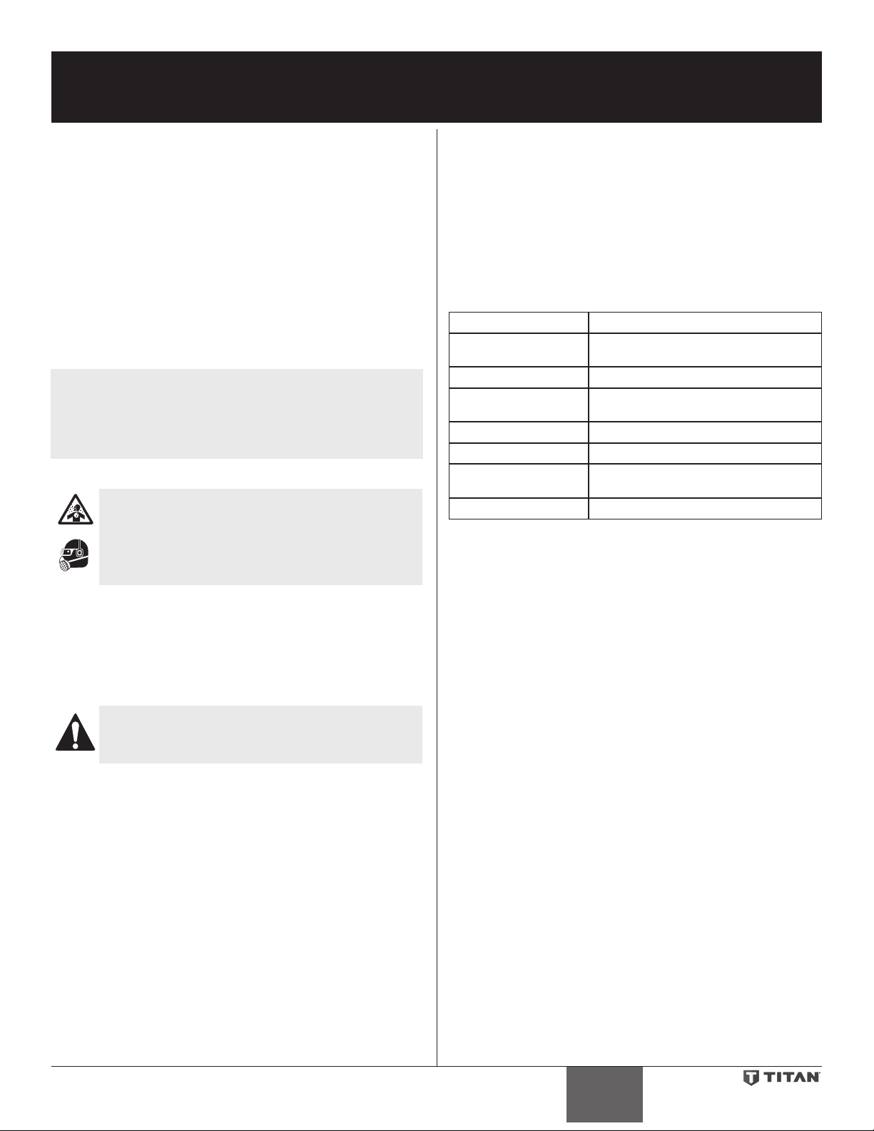
Consignes de sécurite important
et de durée de vie, utiliser exclusivement des tuyaux exibles à haute
pression d‘origine de TITAN.
• Ce système peut produire une pression de 3 300 PSI / 228 Bar.
N’utilisez que les pièces de rechange ou les accessoires spéciés par le
fabricant et ayant une pression nominale minimum de 3 300 PSI. Ceci
est valable pour les embouts de pulvérisation, les protecteurs de buse,
les pistolets, les rallonges, les raccords et le tuyau.
• Verrouillez toujours la détente quand vous ne pulvérisez pas. Vériez
que le verrou de la détente fonctionne correctement.
• Vériez que toutes les connexions sont bien serrées avant d’utiliser
l’appareil.
• Sachez comment arrêter l’appareil et le dépressuriser rapidement.
Soyez bien familiarisé avec les commandes. La pression n’est pas
libérée lorsque le moteur est arrêté. La poignée du robinet-valve
PRIME/SPRAY doit être placée sur PRIME pour libérer la pression.
Consultez la PROCÉDURE DE DÉCOMPRESSION décrite dans le
manuel de la pompe.
• Retirez toujours l’embout de pulvérisation avant de rincer ou de
nettoyer le système.
REMARQUE À L’INTENTION DES MÉDECINS : Les injections cutanées
sont des lésions traumatiques; il importe donc de les traiter sans délai.
On NE DOIT PAS retarder ce traitement sous prétexte de vérier la
toxicité du produit en cause, celle-ci n’étant conséquente que dans le
cas d’injection directe de certains produits dans le système sanguin.
Il pourrait s’avérer nécessaire de consulter un plasticien ou un
spécialiste en chirurgie reconstructive de la main.
MISE EN GARDE : ÉMANATIONS DANGEREUSES
Certains produits (peintures, solvants, insecticides ou
autres) peuvent être nocifs s’ils sont inhalés ou entrent en
contact avec l’organisme. Les émanations de ces produits
peuvent provoquer de graves nausées, évanouissements
ou empoisonnements.
MESURES PRÉVENTIVES :
• Se servir d’un masque ou d’un respirateur s’il y a risque d’inhalation
(lire toutes les directives concernant ces dispositifs an de s’assurer
qu’ils orent la protection requise).
• Porter des lunettes de protection.
• Porter les vêtements de protection prescrits par le fabricant du
produit utilisé.
MISE EN GARDE : GÉNÉRALITÉS
D’autres dangers peuvent entraîner des dommages
matériels ou des blessures graves.
MESURES PRÉVENTIVES :
• Portez toujours les gants, la protection oculaire, les vêtements et un
respirateur ou masque appropriés quand vous peignez.
• Ne travaillez pas et ne pulvérisez pas près d’enfants. Éloignez toujours
les enfants de l’équipement.
• Ne travaillez pas avec les bras au-dessus de la tête ni sur un support
instable. Appuyez-vous bien sur les deux pieds pour toujours
conserver l’équilibre.
• Soyez attentif et regardez ce que vous faites.
• N’utilisez pas l’appareil quand vous êtes fatigué ou sous l’inuence de
drogues ou d’alcool.
• Ne faites pas de nœuds avec le tuyau et ne le tordez pas trop. Le
tuyau à vide peut présenter des fuites suite à l’usure, les nœuds ou
les mauvais traitements. Une fuite risque d’injecter du produit dans la
peau.
• N’exposez pas le tuyau à des températures ou des pressions
supérieures à celles spéciées par le fabricant.
• N’utilisez pas le tuyau pour tirer ou soulever l’équipement.
• Utilisez la plus basse pression possible pour rincer l’équipement.
• Respectez tous les codes locaux, étatiques et nationaux qui régulent
la ventilation, la prévention d’incendies et le fonctionnement.
• Les normes de sécurité du gouvernement des États-Unis ont été
adoptées dans la loi Occupational safety and Health Act (OSHA). Ces
© Titan Tool Inc. Tous droits réservés. 17
normes, en particulier la partie 1910 des Normes générales et la partie
1926 des Normes de construction, doivent être consultées.
• Avant chaque emploi, vériez tous les tuyaux pour détecter
d’éventuelles coupures, fuites, abrasion ou couvercle bombé. Vériez
l’état ou le mouvement des accouplements. Changez immédiatement
le tuyau si l’une de ces conditions est vériée. Ne réparez jamais un
tuyau de peinture. Remplacez-le par un tuyau conducteur à haute
pression.
• Ne pulvérisez pas à l’extérieur par temps venteux.
• Débranchez toujours le cordon électrique de la prise avant de
travailler sur l’équipement.
Spécications
Débit (GPM) 1,0 (3,75 LPM)
Embout, dimension
0,032”
maximale
Pression maximale 3 300 PSI (22,8 MPa)
Source de puissance 2,3 HP moteur DC de Brushless,
100~120V AC, 50/60Hz, 15A
Poids, chariot 83 lbs. (37,6 kg)
Poids, bas chariot 81 lbs. (36,7 kg)
Cordon d’alimentation
300’ (91,4 m)
dimension maximale
Génératrice 5000 W (désactiver la mort en fonction)
Table des matières
Consignes de sécurité ................................................................... 16
Specications ................................................................................. 17
Description générale ..................................................................... 18
Fonctionnement ............................................................................ 18
Utilisation du blocage de la détente du pistolet .............................18
Vérications préliminaires .......................................................................18
Préparation avant de peindre ................................................................19
Peinture ..........................................................................................................19
Panneau de contrôle indicateurs ..........................................................20
Fonctionnement du système de commande Digi-TracMD .... 20-21
Procédure de décompression ................................................................22
Vaporisation .................................................................................. 22
Technique de vaporisation .....................................................................22
Essais préliminaires ....................................................................................22
Nettoyage ...................................................................................... 23
Maintenance .................................................................................. 23
Généralités concernant la maintenance ............................................23
Remplacement des ltres ........................................................................24
Remplacement du moteur ......................................................................24
Remplacement des engrenages ...........................................................25
Remplacement du transducteur ...........................................................25
Remplacement de la soupape PRIME/SPRAY ..................................26
Maintenance de la section des liquides ...................................... 26-28
Dépannage ..................................................................................... 28
Messages d’erreur du système de commande Digi-TracMD ..............29
Listes de pièces .............................................................................. 44
Vue d’ensemble ...........................................................................................44
Boîte d’engrenages ....................................................................................46
Ensemble de chariot ..................................................................................47
Section des liquides ...................................................................................48
Ensemble du ltre ......................................................................................50
Ensemble de basse chariot .....................................................................51
Ensemble d’aspiration (bas chariot) ....................................................52
Étiquettes ......................................................................................................52
Schéma de raccordement électrique ..................................................53
Accessoires ....................................................................................................54
Enregistrement du produit ........................................................... 55
Garantie .......................................................................................... 56
Français
Page 18

Description générale
PRIME/SPR
(côte opposé)
(côte opposé)
12
RapidClean
Arrêt (OFF),
de pression
de pression
Ce vaporisateur à dépression est un outil électrique de précision
servant à atomiser divers types de matériaux. On doit lire et suivre
attentivement les directives apparaissant dans ce manuel pour savoir
comment l’utiliser et le maintenir en bon ordre, et ce, en toute sécurité.
Bouton de
régulation
de pression
Moteur
Système de
commande
Digi-Trac
MC
Vérications préliminaires
On doit procéder aux étapes suivantes avant de brancher le cordon
d’alimentation de l’appareil.
1. S’assurer que le exible et le bloc d’aspiration soient
solidement xés.
2. Fixer un exible de vaporisation à tresse de Nylon, conçu pour
les appareils à dépression, et mesurant au moins 15 mètres
(50 pi).
3. Fixer un pistolet à dépression au exible de vaporisation; ne
pas xer l’embout au pistolet tout de suite (le retirer s’il est
déjà xé).
NOTA : Ne pas encore xer l’embout sur le pistolet de
vaporisation. Démonter l’embout s’il est déjà xé.
Bouchon de
Ensemble
de ltre
Soupape
AY
Raccord de
exible
graisseur
Bouton de
graisseur
Section des
liquides
Flexible
d’aspiration
Tube de
retour
Fonctionnement
Cet appareil produit un jet à très haute pression; avant
de le faire fonctionner, il est donc essentiel de lire et de
comprendre les avertissements formulés dans la section
Consignes de sécurité à l’avant de ce manuel.
Utilisation du blocage de la détente du pistolet
Engagez toujours le blocage de la détente du pistolet lorsque le
pistolet n’est pas utilisé.
1. Pour verrouiller la détente, appuyez sur le verrou de la détente
de gauche à droite, en regardant l’arrière du pistolet.
2. Pour déverrouiller la détente, appuyez sur le verrou de la
détente de droite à gauche, en regardant l’arrière du pistolet.
Détente bloquée
(le pistolet ne
pulvérise pas)
Détente débloquée
(le pistolet pulvérise)
S’assurer que tous les flexibles et pistolets à dépression
soit mis à la terre et conçus pour accepter des pressions
de liquide d’au moins 3 300 lb/po (22,8 MPa).
4. S’assurer que le bouton de régulation de pression soit à la
position OFF (zone noire).
5. S’assurer que le commutateur soit à la position OFF.
6. Enlevez le bouchon de graisseur à l’aide d’un tournevis à tête
plate. Remplir le réservoir avec une once de piston sceau
lubriant (Piston Lube). Remplacer le bouchon de graisseur.
7. Poussez 2-5 fois sur le bouton pour préparer la graisseur.
Pouzzez une fois pour toutes les huit heures d’utilisation pour
lubrier le section de liquides.
IMPORTANT : Ne jamais faire fonctionner l’appareil sans liquide
pendant plus de 10 secondes, ce qui pourrait user inutilement les
tampons graisseurs.
8. S’assurer que l’alimentation électrique soit d’au moins 15 A à
120 V.
9. Brancher le cordon d’alimentation dans une prise
adéquatement mise à la terre située à une distance d’au moins
7,5 m (25 pi) de la surface à vaporiser.
IMPORTANT : Les rallonges utilisées doivent être trifilaires, de
calibre 12 et dotées d’une fiche à broche de MALT; on ne doit
jamais retirer cette troisième broche ou utiliser un adaptateur.
Préparation d’un nouveau vaporisateur
Si cet appareil est neuf, il contient encore un liquide d’essai mis en
usine pour le protéger de la corrosion en cours d’expédition ou
d’entreposage. Ce liquide doit être complètement éliminé au moyen
d’essence minérale avant que l’appareil puisse être utilisé.
IMPORTANT : La détente du pistolet doit toujours être
verrouillée lorsqu’on procède à ces vérifications préliminaires.
1. Mettre le exible d’aspiration dans un contenant d’essence
minérale.
2. Mettre le exible de retour dans un contenant de purge
métallique.
3. Régler la pression au minimum en mettant le bouton de
régulation à la position “MIN”.
Indicatuer
18 © Titan Tool Inc. Tous droits réservés.
Français
Bouton de
zone noir
4. Abaisser la soupape PRIME/SPRAY à la position PRIME.
5. Mettre l’appareil en marche en mettant le commutateur à la
position ON.
6. Laisser le vaporisateur fonctionner pendant 15 à 30 secondes
pour évacuer le liquide d’essai par le exible de retour,
jusqu’au contenant de purge.
7. Arrêter l’appareil en mettant le commutateur à la position
OFF.
RAPID
CLEAN
régulation
Page 19

Préparation avant de peindre
Avant de peindre, il est important de s’assurer que le liquide dans
l’appareil est compatible avec le produit à utiliser.
NOTA : L’incompatibilité liquide/produit peut provoquer le
IMPORTANT : La détente du pistolet doit toujours être verrouillée
lorsqu’on procède à ces vérifications préliminaires.
1. Mettre le exible d’aspiration dans un contenant de solvant
2. Mettre le exible de retour dans un
3. Régler la pression au minimum en
4. Abaisser la soupape PRIME/SPRAY à la
NOTA : Tenez le tube de retour dans le
5. Mettre l’appareil en marche en mettant le commutateur à la
6. Laisser le vaporisateur fonctionner pendant 15 à 30 secondes
7. Arrêter l’appareil en mettant le commutateur à la position OFF.
NOTA : S’assurer que l’embout ou le protège-embout ne
8. Soulever la soupape PRIME/SPRAY à la
9. Mettre l’appareil en marche.
10. Déverrouiller le pistolet en mettant le verrou
11. Appuyer sur la détente en visant le contenant métallique pour
12. Verrouiller le pistolet en mettant le verrou de détente à la
13. Déposer le pistolet et augmenter la pression en tournant
14. Inspecter tous les composants an d’y détecter des fuites
15. Procéder aux étapes de la section Procédure de
blocage des soupapes, ce qui entraînerait le besoin
de démonter et de nettoyer la section des liquides du
vaporisateur.
approprié (de l’eau dans le cas de peintures au latex, de
l’essence minérale dans le cas de peintures à l’huile, etc.).
contenant de purge métallique.
mettant le bouton de régulation à la
position “MIN”.
position PRIME.
conteneur de déchets en faisant
passer le PRIME / SPRAY soupape de
PRIME dans le cas où le pulvérisateur
est sous pression.
position ON.
pour évacuer le solvant usé par le exible de retour, jusqu’au
contenant de purge.
soient pas installés.
position SPRAY.
de détente à la position appropriée.
On doit mettre le pistolet à la terre en
le tenant contre le bord du contenant
de purge métallique pendant qu’il
se vide afin d’éviter les risques de
décharges électrostatiques, lesquelles
peuvent provoquer un incendie.
purger le solvant usé du pistolet, jusqu’à ce que du solvant
frais en ressorte.
position appropriée.
lentement le bouton de régulation vers la droite.
potentielles. Le cas échéant, suivre les directives de la section
Procédure de décompression du présent manuel avant de
xer les exibles et de serrer les raccords.
décompression du présent manuel avant de passer du solvant
au produit de peinture.
RAPID
CLEAN
Peinture
1. Mettre le exible d’aspiration dans un contenant de produit
de peinture.
2. Mettre le exible de retour dans un contenant de purge
métallique.
3. Régler la pression au minimum en mettant le bouton de
régulation à la position “MIN”.
4. Abaisser la soupape PRIME/SPRAY à la position PRIME.
5. Mettre l’appareil en marche en mettant le commutateur à la
position ON.
6. Laisser le vaporisateur fonctionner jusqu’à ce que le produit
commence à s’écouler par le exible de retour dans le
contenant de purge.
7. Arrêter l’appareil en mettant le commutateur à la position OFF.
8. Retirer le exible de retour du contenant de purge et le mettre
à sa position normale, au-dessus du contenant de produit de
peinture.
9. Soulever la soupape PRIME/SPRAY à la position SPRAY.
10. Mettre l’appareil en marche.
11. Déverrouiller le pistolet en mettant le verrou de détente à la
position appropriée.
On doit mettre le pistolet à la terre en
le tenant contre le bord du contenant
de purge métallique pendant qu’il
se vide afin d’éviter les risques de
décharges électrostatiques, lesquelles
peuvent provoquer un incendie.
12. Appuyer sur la détente en visant le contenant métallique pour
purger le solvant et l’air du exible de vaporisation, jusqu’à ce
que le produit de peinture s’écoule librement du pistolet.
13. Verrouiller le pistolet en mettant le verrou de détente à la
position appropriée.
14. Arrêter l’appareil.
15. Fixer l’embout et le protège-embout au pistolet,
conformément aux directives accompagnant ces derniers.
RISQUES D’INJECTION. Ne pas vaporiser sans avoir
installé le protège-embout. Ne jamais appuyer
sur la détente sans avoir mis l’embout en position
de vaporisation ou de désobstruction. Toujours
enclencher le verrou de détente avant de retirer, de
remplacer ou de nettoyer l’embout.
16. Mettre l’appareil en marche.
17. Augmenter la pression en tournant lentement le bouton de
régulation vers la droite, jusqu’à la zone verte, puis eectuer
un essais sur un morceau de carton en examinant le jet
résultant. Régler la pression de manière à ce que le produit
soit parfaitement atomisé.
NOTA : Si la pression est trop élevée, l’embout subira une
usure prématurée et produira des éclaboussures de
surpulvérisation.
On doit effectuer la procédure de décompression chaque
fois qu’on arrête l’appareil pour en faire la maintenance,
en changer les réglages de vaporisation, en remplacer/
nettoyer les embouts ou en effectuer la préparation en
vue d’un nettoyage.
© Titan Tool Inc. Tous droits réservés. 19
Français
Page 20

Indicatuers de panneau de contrôle
de pression
Indicateur de
de f
REG MPa 23.0
VOLUME POMPE
GALLONS XXXXXX
MENU-1 LITRES-2
Voici une description des indicateurs de panneau de contrôle.
Indicateur
marche du
moteur
Fonctionnement du système de commande Digi-Trac
Le système de commande Digi-TracMD est une option qui augmente
la fonctionnalité du pulvérisateur. Il est installé directement sous le
bouton de régulation de la pression du panneau de commande et il
est constitué d’un écran et de quatre touches de fonction. L’achage
montre les diérents écrans de menu, ce qui permet à l’utilisateur de
personnaliser et de surveiller le fonctionnement du pulvérisateur à
l’aide des touches de fonction.
Indicateur de Pression
L’indicateur de pression ache la pression de travail actuelle du
vaporisateur. Il a trois niveaux d’indication : jaune clignotant, jaune
xe et vert xe.
Jaune Clignotant
Lorsque l’indicateur de pression est jaune clignotant, l’appareil
fonctionne à une pression comprise entre 0 et 200 PSI. Un indicateur
de pression jaune clignotant signie :
• Que l’appareil est branché et en position “ON”.
• L’appareilest à une pression d’amorçage (peu ou pas de
• Il est possible sans danger de placer la soupape PRIME/SPRAY
• Il est possible et sans danger de changer ou de remplacer
Jaune Fixe
Lorsque l’indicateur de pression est jaune xe, l’appareil fonctionne
à une pression comprise entre 200 et 1800 PSI. Un indicateur de
pression jaune xe signie :
• Que l’appareil est à la bonne pression pour vaporiser de la
• Si l’indicateur de pression passe au jaune xe lorsque la
Vert Fixe
Lorsque l’indicateur de pression est vert xe, l’appareil fonctionne
à une pression comprise entre 1800 et 3300 PSI. Un indicateur de
pression vert xe signie :
• L’appareil est réglé sur la bonne pression pour vaporiser des
• L’appareil fonctionne à plein régime avec une pression élevée.
Indicateur de Fonctionnement du Moteur
L’indicateur de Fonctionnement du Moteur est allumé lorsque le
moteur est mis en marche. Cet indicateur est utilisé par les centres
techniques pour réparer les problèmes de moteur.
20 © Titan Tool Inc. Tous droits réservés.
RAPID
CLEAN
pression)
entre deux positions.
l’embout de vaporisation (consulter le manuel de l’embout
concernant les procédures de remplacement).
NOTA : Si l’indicateur de pression commence à clignoter
en jaune lorsque le bouton de commande de la
pression est réglé sur une pression supérieure et que
la soupape de PRIME/SPRAY est en position SPRAY,
soit l’embout de vaporisation est usé, soit il y a une
fuite, soit l’appareil doit être entretenu/réparé.
teinture, de la laque, du vernis et des peintures multicolores.
pression est réglée pour démarrer en vert xe, cela signie
l’un des points suivants :
a. Indicateur d’Usure d’Embout – lors de la vaporisation avec du
latex ou à haute pression, le jaune xe apparaît. Ceci signie
que l’embout est usé et doit être remplacé.
b. Embout Trop Grand – lorsqu’un embout est trop grand pour
l’appareil est installé sur le pistolet, l’indicateur de pression
passe de vert xe à jaune xe.
c. Usure de la Section des Fluides – si un indicateur de pression
jaune xe apparaît lorsqu’on utilise un nouvel embout et que la
pression est réglée au maximum, il est peut être nécessaire de
réparer l’appareil (tampons graisseurs usés, piston usé, soupape
collée, etc).
peintures d’intérieur à l’huile ou au latex.
NOTA : Les indicateurs de marche et de pression qui
clignotent en alternance indiquent que le moteur est
en surchaue. Arrêtez la pompe (position « ARRÊT »)
et laissez-la refroidir.
Français
Achage
Touches
onction
SET PSI 3000
ACTUAL PSI 2950
Touches de fonction
Les touches de fonction sont numérotées de 1 à 4. Chaque touche
porte également l’étiquette d’une fonction supplémentaire.
No 1/Touche
« Menu »
No 2/Touche
« + »
No 3/Touche
« - »
No 4/Touche
« Sélectionner »
Appuyer sur la touche no 1 pour faire déler les
écrans de menu disponibles ou pour exécuter
une fonction de l’écran de menu actif.
Appuyer sur la touche no 2 pour exécuter
une fonction de l’écran de menu actif ou pour
augmenter une valeur.
Appuyer sur la touche no 3 pour exécuter
une fonction de l’écran de menu actif ou pour
diminuer une valeur.
Appuyer sur la touche no 4 pour sélectionner
l’écran de menu actif ou pour exécuter une
fonction de l’écran de menu actif.
Écrans de menu
De nombreux écrans de menu sont disponibles pour permettre à
l’utilisateur de personnaliser et de surveiller le fonctionnement du
pulvérisateur. Ce sont : l’écran principal, l’écran des gallons pompés,
l’écran des volume nécessaires au travail, l’écran du numéro de série
de l’appareil, l’écran des indicateurs de durée, l’écran des indicateurs
de durée du travail, l’écran de la durée d’utilisation, l’écran de
pression, l’écran du code de sécurité, l’écran d’amorçage et l’écran de
nettoyage rapide.
Écran principal
L’écran principal est l’écran par défaut du
système de commande qui apparaît au
démarrage du pulvérisateur.
Appuyer sur la touche no 2 pour basculer entre les unités PSI, Bar et
MPa. Appuyer sur la touche no 1 pour faire dérouler les écrans de
menu disponibles.
NOTA : Dans le cas des pulvérisateurs ayant le numéro de
série « 15xxx01001 » et plus élevé, il est possible de
changer la langue du texte en suivant la procédure
qui suit.
L’activation de la touche n° 3 dans le Main Screen
(Fenêtre principale) permet de changer la langue
du texte aché à l’écran. Neug langues sont
disponibles au total. À chaque fois que vous
appuyez sur la touche n° 1, une langue diérente
apparaît. Ces langues, dans l’ordre d’apparition,
sont: anglais, espagnol, néerlandais, danois,
suédois, allemand, français, italien, et portugais.
Écran « Volume pompés » (Volume Pumped)
L’écran « Volume pompés » ache la
quantité totale des gallons ou des litres
pulvérisés par le pulvérisateur.
Pour sélectionner l’écran « Volume
pompé », appuyer sur la touche no 4.
MPa ACTUEL 22.5
SELECT-4MENU-1
Page 21

Écran « Volume nécessaires au travail » (Job Volume)
VOLUME TRAVAIL
SELECT-4MENU-1
GALLONS X
MENU-1 REINI-3
No SERIE UNITE
# SER XXXXXXXXXX
COMPTEURS
A HEURE
TPS EXE
XXXX
XXXX
COMPTEURS TRAV
A HEURE X
REINI-3MENU-1
TEMPS DE SERVICE
SERVICE @ XX
CODE SECURITE
CHANGE-2MENU-1
SAISIR ANCIEN
SAISIR NOUVEAU
RECYCLAGE
NETTOYAGA
L’écran « Volume nécessaires au travail »
permet à l’utilisateur de remettre à l’état
initial le compteur de gallons, an de connaître la quantité nécessaire
à un travail précis.
Pour sélectionner l’écran « Volume
nécessaire au travail », appuyer sur la
touche no 4.
Écran « No de série de l’appareil » (Unit Serial #)
L’écran « No de série de l’appareil » ache
le numéro de série du pulvérisateur.
Pour sélectionner l’écran « No de série de
l’appareil », appuyer sur la touche no 4.
MENU-1
Écran « Indicateurs de durée » (Timers)
L’écran « Indicateurs de durée » ache la
durée totale depuis la mise sous tension
du pulvérisateur ainsi que la durée totale
d’utilisation du pulvérisateur (pompage).
Pour sélectionner l’écran « Indicateurs de
durée », appuyer sur la touche no 4.
Écran « Indicateurs de durée du travail » (Job Timers)
L’écran « Indicateurs de durée du travail »
permet à l’utilisateur de remettre à l’état
initial l’indicateur « Durée de mise sous
tension » et l’indicateur « Durée d’utilisation », an de connaître la
durée d’un travail précis.
Pour sélectionner l’écran « Indicateurs de
durée du travail », appuyer sur la touche
no 4. L’écran « JOB ON » sera aché.
Appuyer sur la touche no 3 an de
TPS EXE X
réinitialiser. Appuyer sur la touche no 1
an de passer à l’écran « JOB RUN ». Appuyer sur la touche no 3 an
de réinitialiser. Appuyer sur la touche 1 an de faire déler les écrans
restants.
Écran « Durée d’utilisation » (Service Time)
L’écran « Durée d’utilisation » permet à
l’utilisateur de régler l’intervalle entre les
périodes d’entretien (en heures). Sous le
Chronomètre d’entretien gure à l’écran
le nombre d’heures du pulvérisateur depuis la dernière activation
du chronomètre d’entretien. Pour sélectionner l’écran Chronomètre
d’entretien, appuyez sur la touche no 4.
Pour régler l’heure d’entretien, appuyez
sur les touches no 2 (ascendante) et/
H TRAVAIL XX
ou no 3 (descendante) jusqu’à l’heure
souhaitée (les heures d’exécution augmenteront/diminueront de 25
échelon chaque fois que vous appuierez sur l’une des touches).
Lorsque le pulvérisateur atteint la SERVICE@ sélectionnée, l’écran
achera « SERVICE DUE » (entretien requis). An de réinitialiser la
durée, appuyer sur la touche no 3 lorsque la pompe est allumée. Cela
réinitialisera le message « SERVICE DUE » et réinitialisera également la
« SERVICE TIME » au paramètre précédent.
Écran « Code de sécurité » (Security Code)
L’écran « Code de sécurité » permet à
l’utilisateur de programmer un code
de sécurité à quatre chires, an d’éviter l’utilisation non autorisée
du pulvérisateur. Si un code de sécurité a été programmé, l’écran
du système de commande demandera un code au démarrage de
l’appareil. Si le bon code est saisi, l’écran achera l’écran principal
et le pulvérisateur fonctionnera. Si un mauvais code est saisi, l’écran
demandera de saisir le bon code et le pulvérisateur ne fonctionnera
pas. Pour programmer ou changer le code de sécurité, appuyer sur la
touche no 2.
© Titan Tool Inc. Tous droits réservés. 21
NOTA : Si le pulvérisateur est neuf, aucun code de sécurité
n’est programmé et l’écran principal s’ache au
démarrage de l’appareil. Lorsque vous réglerez
un code de sécurité pour la première fois, l’écran «
Entrez l’ancien numéro de code » (“Enter Old Code
Number”) apparaîtra, et vous devrez entrer « 1111 ».
Saisir l’ancien code de sécurité pour
atteindre l’écran permettant le
NUMERO CODE
changement du code. Si le mauvais code
est saisi, l’écran demande de saisir le bon code, et le code de sécurité
ne peut pas être changé.
SELECT-4MENU-1
Saisir le nouveau code de sécurité. Une
fois que le code est saisi, l’écran demande
automatiquement de ressaisir le nouveau
code pour vérication. Si le nouveau code
est ressaisi correctement, l’écran conrme
que le nouveau code a été enregistré et
NUMERO CODE XXXX
RE-SAISIR NOUVEAU
NUMERO CODE XXXX
NOUVEAU CODE
ACCEPTE
retourne à l’écran principal. Si le nouveau
SELECT-4MENU-1
code n’est pas ressaisi correctement, l’écran retourne à l’écran « Saisir
le nouveau code » et le processus est à recommencer.
Si vous oubliez ou égarez vitre code de sécurité, vous pouvez appeler
le Service à la clientèle de Titan pour qu’il vous aide.
NOTA : Pour désactiver la fonction de sécurité de
verrouillage numérique antivol, saisir « 1111 »
à l’écran « Saisir le nouveau code » (c’est le code
par défaut permettant de laisser le pulvérisateur
non verrouillé). Ainsi, ce sera l’écran principal qui
SELECT-4MENU-1
s’achera au démarrage du pulvérisateur.
Écran « Recyclage » (Prime)
L’écran « Recyclage » apparaît lorsque le
REINI-3MENU-1
bouton de régulation de la pression est
programmé au minimum « MIN ».
Écran « Nettoyage rapide » (Rapid Clean)
L’écran « Nettoyage rapide » apparaît
lorsque le bouton de régulation de la
pression est réglé à la position RAPID CLEAN et que la soupape
PRIME/SPRAY est à la position PRIME.
NOTA : Si rien n’est eectué sur aucun des écrans de menu
SELECT-4MENU-1
pendant plus de 30 secondes, l’écran retourne à
l’écran principal.
Procédure de décompression
On doit effectuer la procédure de décompression chaque
fois qu’on arrête l’appareil pour en faire la maintenance,
en changer les réglages de vaporisation, en remplacer/
nettoyer les embouts ou en effectuer la préparation en
vue d’un nettoyage.
1. Verrouiller le pistolet en mettant le verrou de détente à la
position appropriée.
2. Arrêter l’appareil en mettant le commutateur à la position
OFF.
3. Tourner le bouton de régulation de la pression vers la gauche,
jusqu’à la position OFF, dans la zone noire.
4. Déverrouiller le pistolet en mettant le verrou de détente à la
position appropriée.
5. Tenir fermement la partie métallique du
pistolet contre le bord d’un contenant
métallique an d’éviter une accumulation
d’électricité statique.
6. Appuyer sur la détente du pistolet an de
purger tout l’air restant dans le exible.
7. Verrouiller le pistolet en mettant le verrou de détente à la
position appropriée.
8. Abaisser la soupape PRIME/SPRAY à la position PRIME.
Français
Page 22

Vaporisation
mouvemen
t
Mouvements semi-circulaires Pistolet incliné
RISQUES D’INJECTION. Ne pas vaporiser sans avoir
installé le protège-embout. Ne jamais appuyer
sur la détente sans avoir mis l’embout en position
de vaporisation ou de désobstruction. Toujours
enclencher le verrou de détente avant de retirer, de
remplacer ou de nettoyer l’embout.
Technique de vaporisation
En suivant les techniques suivantes, on s’assure d’obtenir des
résultats d’allure professionnelle.
Tenir le pistolet perpendiculairement par rapport à la surface,
toujours à la même distance de cette dernière (selon le produit
utilisé, la surface en présence et la forme de jet désirée, cette distance
devrait se situer entre 30 et 35 cm [12 et 14 po]).
Procéder verticalement ou horizontalement à un rythme régulier, ce
qui aura pour eet de minimiser le gaspillage de produit et d’assurer
une couverture égale. Le rythme idéal permet d’appliquer une
couche chargée sur toute la surface, sans gouttes ni coulées.
En tenant le pistolet plus près de la surface, on y applique davantage
de produit, mais sur une bande plus étroite, tandis qu’en l’éloignant,
on obtient une couche moins épaisse, répartie sur une plus grande
largeur. En présence de gouttes, de coulées ou de surpulvérisation,
on doit opter pour un embout doté d’un plus petit orice; s’il n’y
a pas assez de produit sur la surface, ou si on désire procéder plus
rapidement, il est préférable de choisir un embout à orice plus
grand.
On doit procéder par gestes réguliers et uniformes, en inversant
les mouvements à chaque passage (de haut en bas, puis de bas en
haut, ou de gauche à droite, puis de droite à gauche). Amorcer le
mouvement avant d’appuyer sur la détente.
Amorcer le
Appuyer sur
t
la détente
Relâcher
la détente
Terminer le
mouvemen
Il est essentiel de faire chevaucher chacun des passages pour obtenir
un ni uniforme. Si, par exemple, on procède horizontalement, il
faut commencer par le haut, puis viser le bord inférieur du passage
précédent de manière à en chevaucher la moitié.
Bords chevauchants
er
1
passage
e
2
passage
e
3
passage
e
4
passage
e
5
passage
Lorsqu’on utilise un écran
protecteur, celui-ci doit être
fermement maintenu contre
la surface. Le pistolet doit être
légèrement incliné de manière à
éloigner le jet de l’écran, ce qui
évitera de faire pénétrer le produit de peinture sous ce dernier.
On doit également protéger les arbustes près des bâtiments en les
attachant et en les couvrant d’une toile. Cette toile doit cependant
être retirée dans les plus brefs délais. Les rallonges de pistolet Titan
peuvent, elles aussi, s’avérer fort utiles dans de telles situations.
Les objets comme les voitures, l’ameublement de jardin, etc. doivent
être éloignés ou recouverts lorsqu’ils sont à proximité de la surface
à vaporiser. Il faut toujours s’assurer de protéger les éléments
susceptibles d’être endommagés par des éclaboussures.
Il faut éviter de procéder par gestes semi-circulaires ou d’incliner le
pistolet par rapport à la surface, ce qui produirait un ni inégal.
Vaporisation
hors cible
Trop épais
Essais préliminaires
1. S’assurer que le exible à produit de peinture soit exempt de
coudes et éloigné de toute arête coupante.
2. Régler la pression au minimum en mettant le bouton de
régulation à la position “MIN”.
3. Soulever la soupape PRIME/SPRAY à la position SPRAY.
4. Tourner le bouton de régulation de pression à son réglage le
plus élevé; le exible à produit devrait se raidir sous l’eet de
la pression.
5. Déverrouiller la détente du pistolet.
6. Appuyer sur la détente pour évacuer l’air du exible.
7. Quand la peinture atteint l’embout, eectuer un essai de
vaporisation en vue de régler le jet en fonction du travail à
eectuer.
8. Régler la pression au niveau le
plus bas qui permette d’obtenir
le jet désiré. Si la pression est
trop élevée, le jet sera trop
dispersé; si elle est trop basse,
le jet produira des traînées
ou crachera des grumeaux de
produit.
Jet ecace
Traînées de produit
22 © Titan Tool Inc. Tous droits réservés.
Français
Page 23

Nettoyage
Directives particulières pour le nettoyage au moyen de
solvants inflammables :
• Purger le pistolet à l’extérieur de préférence, à une distance
d’au moins une longueur de exible de la pompe.
• Si le solvant usé est recueilli dans un contenant métallique
de 4 litres (1 gallon), celui-ci doit être inséré dans un second
contenant d’au moins 20 litres (5 gallons).
• L’endroit choisi doit être exempt de vapeurs inammables.
• On doit suivre les directives de nettoyage à la lettre.
IMPORTANT : Le vaporisateur, le flexible et le pistolet doivent
être nettoyés en profondeur après chaque journée d’utilisation
et ce, afin d’éviter les accumulations de produit susceptibles de
nuire grandement au rendement de l’appareil.
Lorsqu’on se sert d’essence minérale ou d’autres
solvants pour nettoyer le vaporisateur, le flexible ou
le pistolet, on doit régler la pression au minimum et
retirer l’embout de la buse du pistolet. L’accumulation
d’électricité statique risque de provoquer des
incendies en présence de vapeurs inflammables.
1. Suivre la Procédure de décompression à la section
Fonctionnement du présent manuel.
2. Retirer l’embout et le protège-embout, et les nettoyer au
moyen d’une brosse et du solvant approprié.
3. Mettre le exible d’aspiration dans un contenant de solvant
approprié (de l’eau dans le cas de peintures au latex, de
l’essence minérale dans le cas de peintures à l’huile, etc.).
4. Mettre le exible de retour dans un contenant de purge
métallique.
5. Abaisser la soupape PRIME/SPRAY à la position PRIME.
NOTA : Tenez le tube de retour dans le conteneur de déchets
6. Régler la pression pour le RAPID CLEAN
7. Mettre l’appareil en marche en mettant le
8. Laisser le solvant circuler dans l’appareil
9. Arrêter l’appareil en mettant le commutateur
10. Soulever la soupape PRIME/SPRAY à la
11. Mettre l’appareil en marche.
12. Appuyer sur la détente en visant le contenant métallique pour
13. Continuer d’appuyer sur la détente, en direction du contenant
en faisant passer le PRIME / SPRAY soupape de PRIME
dans le cas où le pulvérisateur est sous pression.
par pulsations en mettant le bouton de
régulation à la position RAPID CLEAN.
RAPID
commutateur à la position ON.
pour évacuer le produit de peinture par le exible de retour,
jusqu’au contenant de purge.
à la position OFF.
position SPRAY.
On doit mettre le pistolet à la terre en
le tenant contre le bord du contenant
de purge métallique pendant qu’il
se vide afin d’éviter les risques de
décharges électrostatiques, lesquelles
peuvent provoquer un incendie.
purger le produit du exible, jusqu’à ce que le solvant s’écoule
du pistolet.
métallique, jusqu’à ce que le solvant évacué soit propre.
CLEAN
14. Suivre la Procédure de décompression à la section
Fonctionnement du présent manuel.
15. Débrancher l’appareil et le ranger dans un endroit propre et
sec.
IMPORTANT : Ne pas ranger l’appareil sous pression.
Maintenance
Avant de procéder, on doit suivre les directives de
la section Procédure de décompression du présent
manuel. On doit également respecter tous les autres
avertissements si on veut éviter les blessures par
injection, par contact avec une pièce mobile ou par
choc électrique. Le vaporisateur doit toujours être
débranché avant d’être entretenu ou réparé.
Généralités concernant la maintenance
Pour réparer ou entretenir le vaporisateur, on pourrait avoir à recourir
aux outils suivants :
Tournevis étoile Clé hexagonale de 1,0 cm (3/8 po)
Pince à bec pointu Clé hexagonale de 0,8 cm (5/16 po)
Clé à ouverture variable Clé hexagonale de 0,6 cm (1/4 po)
Maillet en caoutchouc Clé hexagonale de 0,5 cm (3/16 po)
Tournevis plat Clé hexagonale de 0,4 cm (5/32 po)
Clé hexagonale de 0,3 cm (5/64 po)
1. Avant de procéder à la maintenance de n’importe quel
composant du vaporisateur, il faut lire attentivement
les directives ainsi que tous les avertissements qu’elles
contiennent.
IMPORTANT : Ne jamais tirer sur le cordon pour le débrancher,
ce qui pourrait détacher le connecteur des fils.
2. Vérier les résultats de la maintenance eectuée avant
d’utiliser le vaporisateur en conditions normales an de
s’assurer que le problème ait bel et bien été corrigé. Si le
vaporisateur ne fonctionne toujours pas comme il faut,
repasser la procédure pour s’assurer qu’elle ait été bien suivie.
Se reporter ensuite à la section Dépannage pour cerner la
source potentielle du problème.
3. S’assurer que l’endroit choisi soit bien ventilé si des solvants
sont utilisés pour le nettoyage. Toujours porter des lunettes
de protection lorsqu’on procède à la maintenance. D’autres
dispositifs protecteurs pourraient être requis selon le type
de solvant utilisé; on doit toujours communiquer avec le
fabricant de ce dernier pour obtenir ses recommandations à
cet eet.
4. Pour toute autre question relative à ce vaporisateur à
dépression, il sut de communiquer avec Titan :
Service à la clientèle (É.-U.) .............................. 1-800-526-5362
Télécopieur ................................................. 1-800-528-4826
NOTA : Pour l’entreposage à long terme en milieu froid,
remplir tous les composants de l’appareil d’essence
minérale.
Dans le cas de rangement à court terme après
utilisation de peinture au latex, remplir tous les
composants d’eau mélangée au protecteur Titan Liquid
Shield (se reporter à la section Accessoires du présent
manuel pour obtenir le numéro de pièce de ce produit).
© Titan Tool Inc. Tous droits réservés. 23
Français
Page 24

Remplacement des ltres
Vis du carter de moteur
Carter de boîte
Vis de
Filtre de pompe
1. Dévissez et retirez
manuellement le corps de ltre.
2. Retirez le ltre du ressort
intérieur.
3. Examinez le ltre et nettoyez-le
ou remplacez-le au besoin.
4. Examinez le joint torique et
nettoyez-le ou remplacez-le au
besoin.
5. Remettez en place l’adaptateur
du ressort intérieur et placez le
nouveau ltre ou le ltre nettoyé
sur le ressort intérieur. Insérez le
ltre au centre du logement de
ltre.
6. Glissez le corps de ltre sur
le ltre et vissez-le dans le
logement de ltre jusqu’à ce
qu’il soit solidement xé.
NOTA : Le logement de ltre
doit être serré à la
main. Assurez-vous
qu’il est bien enclavé
dans le bloc de la
pompe.
Filtre de pistolet
1. Détachez le dessus du pontet de la corps du pistolet.
2. En se servant de la partie inférieure du pontet comme clé,
desserrez et enlevez l’ensemble de la poignée de la tête du
pistolet.
3. Extrayez le ltre usagé de la corps du pistolet. Nettoyez ou
remplacez.
4. Faites glisser le nouveau ltre, la partie letée en premier,
dans la corps du pistolet.
5. Placez le joint de la poignée dans la corps du pistolet avec la
partie plate du joint vers la tête du pistolet. Serrez à l’aide de
la clé de la détente.
6. Enclenchez à nouveau le pontet sur la corps du pistolet.
Corps de
ltre
Ressort
du ltre
Filtre
Adaptateur
Ressort du
support du
ltre
Joint
torique
Logement
du ltre
Corps du
pistolet
Filtre
Poignée
Remplacement de l’ensemble de moteur
1. Débranchez l’appareil.
2. Dévissez et retirez les deux (2) vis du capot du moteur. Retirez
le capot.
3. Dévissez et retirez les trois (3) vis du ventre pan. Retirez le
ventre pan.
4. Dévissez et retirez les deux (2) vis du carter de moteur. Retirez
le carter.
5. Débranchez tous les ls reliant le moteur au pulvérisateur.
6. Dévissez et retirez les quatre (4) vis du panneau de
commandes. Retirez le panneau de commandes.
7. Débranchez les ls reliant le moteur au panneau de
commandes.
8. Dévissez et retirez les deux (2) vis du contrôleur de moteur.
Retirez le contrôleur de moteur.
9. Dévissez et retirez les quatre (4) vis du joint d’étanchéité du
moteur. Retirez le joint d’étanchéité.
10. Dévissez et retirez les six (6) vis de montage de moteur.
11. Retirez le moteur du carter de boîte d’engrenages.
12. Une fois le moteur retiré, vériez si les roues d’engrenage dans
le carter de boîte d’engrenages sont endommagées ou très
usées. Remplacez les roues d’engrenage au besoin.
13. Placez le nouveau moteur dans le carter de boîte
d’engrenages.
14. Fixez solidement le moteur au moyen des six (6) vis de
montage du moteur.
15. Raccordez les ls reliant le pulvérisateur au moteur (consultez
le schéma de raccordement électrique sous la rubrique « Liste
des pièces » du présent manuel).
16. Placez le joint d’étanchéité au bout de l’ensemble de moteur.
Fixez-le solidement au moyen des quatre (4) vis de joint
d’étanchéité.
17. Replacez le contrôleur de moteur derrière le joint
d’étanchéité. Fixez-le solidement au moyen des deux (2) vis
du contrôleur de moteur.
18. Raccordez tous les ls reliant le moteur au pulvérisateur.
19. Raccordez tous les ls reliant le moteur au panneau de
commandes.
20. Replacez le panneau de commandes et xez-le solidement au
moyen des quatre (4) vis du panneau de commandes.
21. Remettez le carter de moteur sur le contrôleur de moteur.
Fixez-le solidement au moyen des deux (2) vis du carter de
moteur.
22. Remettez en place le ventre pan et xez-le solidement au
moyen des trois (3) vis de ventre pan.
23. Placez le capot du moteur sur l’ensemble de moteur.
24. Fixez solidement le capot du moteur au moyen des deux (2)
vis du capot du moteur.
panneau de
commandes
d’engrenages
Capot du moteur
Vis de montage
de moteur
Moteur
NOTA : Pour obtenir plus de détails, se renseigner sur les
numéros de pièce ou voir des dessins d’assemblage
à plus grande échelle, se reporter au manuel de
l’utilisateur du pistolet à dépression professionnel
RX-Pro.
24 © Titan Tool Inc. Tous droits réservés.
Français
Panneau
de commandes
Vis de
ventre pan
Ventre pan
Joint
d’étanchéité
Vis de joint
Vis du capot
du moteur
Vis du contrôleur de moteur
d’étanchéité
Contrôleur de moteur
Carter de moteur
Page 25

Remplacement des roues d’engrenage
1. Suivez les étapes 1 à 11 sous la rubrique Remplacement de
l’ensemble de moteur (page 24) pour retirer le moteur et le
panneau de commandes.
2. Vériez si l’engrenage d’armature au bout du moteur est
endommagé ou très usé. S’il est complètement usé, remplacez
l’ensemble de moteur.
3. Retirez les engrenages du 1er et du 2e étage et vériez s’ils
sont endommagés ou très usés. Remplacez-les au besoin.
4. Vériez si l’ensemble de boîte d’engrenages avant est
endommagé ou très usé. Le cas échéant, remplacez
l’ensemble.
NOTA : Nettoyez la cavité de la boîte d’engrenages et la
remplir de Lubriplate (no de pièce 314-171) jusqu’à
la face arrière de chacun des engrenages.
5. Replacez le moteur dans le carter de boîte d’engrenages.
6. Suivez les étapes 13 à 24 sous la rubrique Remplacement de
l’ensemble de moteur (page 24) pour remplacer le moteur et
le panneau de commandes.
Engrenage d’armature
9. Vissez le câble du nouveau transducteur à travers la plaque
d’assemblage et raccordez-le à le contrôleur de moteur.
10. Vissez le nouveau transducteur dans le logement de ltre et
xez-le solidement à l’aide d’une clé plate.
NOTA : Assurez-vous que le joint torique du transducteur
soit bien en place avant de visser le transducteur
dans le logement de ltre.
11. Poussez l’anneau isolant dans la plaque d’assemblage.
12. Branchez le câble du transducteur à le contrôleur de moteur
(consultez le schéma de raccordement électrique sous la
rubrique « Liste des pièces » du présent manuel).
13. Replacez le carter de moteur sur le contrôleur de moteur.
Fixez-le solidement au moyen des deux (2) vis du carter de
moteur.
14. Remettez le capot du moteur sur l’ensemble de moteur.
15. Fixez solidement le capot du moteur au moyen des deux (2)
vis du capot du moteur.
Capot du moteur
Engrenage du 1er étage
Engrenage du 2e étage
Vis de ventre pan
Rondelle de butée
Ventre pan
Ensemble de boîte d’engrenages avant
Remplacement du transducteur
1. Débranchez l’appareil.
2. Dévissez et retirez les
deux (2) boulons de
l’ensemble de ltre.
Retirez l’ensemble de
ltre du chariot.
3. Dévissez et retirez les
deux (2) vis du capot du
moteur. Retirez le capot
du moteur.
4. Dévissez et retirez les
deux (2) vis du carter de
moteur. Retirez le carter
du moteur.
5. Débranchez le câble du
transducteur du contrôleur de moteur.
6. Retirez l’anneau isolant de la plaque d’assemblage et faites-le
glisser sur l’arbre du transducteur de sorte qu’il ne touche plus
la plaque d’assemblage.
7. À l’aide d’une clé plate, dévissez et retirez le transducteur
du logement de ltre. Dévissez délicatement le câble du
transducteur à travers la plaque d’assemblage.
8. Retirez l’anneau isolant du vieux transducteur et placez-le sur
le nouveau.
Vis du
carter du
moteur
Vis du capot
du moteur
Contrôleur
de moteur
Carter du
moteur
Anneau isolant
Transducteur
Ensemble de ltre
© Titan Tool Inc. Tous droits réservés. 25
Français
Page 26

Remplacement de la soupape PRIME/SPRAY
t
Manette de
clapet de pied
appui
clapet de pied
clapet de pied
clapet de pied
Logement
tie
Siège de soupape
é
Logement
Suivez les directives ci-dessous en se servant de la trousse de
remplacement de la soupape PRIME/SPRAY (no de pièce 700-248).
1. Poussez la goupille hors de la manette de soupape.
2. Retirez la manette de soupape et la base à came.
3. À l’aide d’une clé plate, desserrez et retirez le logement de
soupape.
4. Assurez-vous que le joint statique est bien en place, et vissez
le nouveau logement de soupape dans le bloc ltre. Serrez à
l’aide d’une clé plate.
5. Placez la base à came sur le logement de soupape. Lubriez la
base à came à l’aide de graisse et alignez la came avec le bloc
ltre à l’aide de la goupille de positionnement.
6. Alignez le trou de la tige de soupape avec celui de la manette
de soupape.
7. Insérez la goupille dans la manette de soupape à travers la
tige de soupape pour verrouiller la manette de soupape.
Joint statique
Logement de soupape
Goupille de
positionnement
Base à came
soupape
Tige de soupape
Goupille
Logemen
de ltre
Entretien de la section de liquide
Suivez les directives suivantes pour l’entretien des soupapes et le
remplacement des garnitures d’étanchéité de la section de liquide.
Suivez chacune de ces étapes avant de procéder à l’entretien de la
section de liquide.
1. Dévissez et retirez les quatre vis du couvercle avant. Retirez le
couvercle avant.
2. Réglez la pression au minimum en tournant le bouton de
régulation de la pression à « MIN ». L’écran Digi-TracMC devrait
acher « PRIME ».
3. Appuyez sur la touche no 1 du panneau de commandes Digi-
TracMC. L’écran « CREEP MODE » s’achera.
4. Tournez lentement le bouton de régulation de la pression
dans le sens des aiguilles d’une montre an d’augmenter
la pression. L’ensemble de vilebrequin/bielle s’activera très
lentement.
5. Lorsqu’il atteint le point mort de sa course, ramenez le bouton
de régulation de la pression à « MIN ». Le mouvement de
l’ensemble de vilebrequin/bielle devrait s’arrêter.
6. Arrêtez la pompe et débranchez l’appareil.
Avant de commencer l’entretien, suivez la procédure
de décompression susmentionnée. Suivez également
toutes les autres mises en garde afin de réduire les
risques de blessures par injection, de blessures liées
à des pièces en mouvement et de chocs électriques.
Débranchez toujours le pulvérisateur avant l’entretien!
7. Retirez le tuyau de retour de la bride de serrage du tube-
siphon.
8. Dévissez le tube-siphon/jeu de siphons du clapet de pied.
9. Dévissez et retirez le tuyau à haute pression du raccord
derrière le logement supérieur de la section de liquide.
Entretien des soupapes et clapets
La conception de la section de liquide
permet l’accès au clapet de pied et au
siège de clapet ainsi qu’à la soupape
de sortie et au siège de soupape sans
devoir démonter complètement
la section de liquide. Il est possible
que les soupapes ne soient pas bien
assises en raison de la présence de
débris coincés dans le siège du clapet
de pied ou de la soupape de sortie.
Suivez les directives suivantes pour
nettoyer les soupapes et les clapets
et inverser ou remplacer les sièges.
1. Desserrez et retirez le
logement de clapet de pied
du logement inférieur.
2. Retirez les débris du logement
de clapet de pied et examinez
le logement et le siège du
clapet. Inversez ou remplacez
le siège s’il est endommagé.
3. Retenez le logement supérieur aux surplats de serrage à l’aide
d’une clé plate, et dévissez le logement inférieur à l’aide d’une
autre clé. Retirez le logement inférieur.
4. À l’aide d’une clé 3/8 po., dévissez et retirez la rondelle de
retenue de soupape de sortie de la tige de piston.
NOTA : Assurez-vous que
la tige de piston
est bien reliée à la
pompe avant de
procéder à l’entretien
de la soupape de
sortie. Cette mesure
empêchera la tige
de piston de pivoter
pendant le démontage
de la soupape de
sortie.
5. Retirez les débris et examinez
la rondelle de retenue et le
siège de soupape de sortie.
Inversez ou remplacez le siège
s’il est endommagé.
6. Retirez, nettoyez et examinez
la cage de soupape de sortie
et la bille de soupape de
sortie. Remplacez-les si elles sont usées ou endommagées.
7. Remontez les soupapes en inversant les étapes ci-dessus.
NOTA : Pendant le remontage, assurez-vous que les joints
toriques en Viton et les bagues d’appui en PTFE
entre les logements supérieur et inférieur et entre
le logement inférieur et celui du clapet de pied sont
bien en place et lubriés à l’aide de graisse.
supérieur
Logement
inférieur
Cage de
Bille de
Siège de
Joint torique
Joint torique
en Viton
Bague d’
en PTFE
Logement de
supérieur
Tige de piston
Joint d’étanchéit
de la soupape
de sortie
Cage de soupape
de sortie
Bille de soupape
de sortie
Rondelle
en nylon
de sortie
Rondelle de
retenue de
soupape de sor
Logement
inférieur
26 © Titan Tool Inc. Tous droits réservés.
Français
Page 27

Remplacement des garnitures d’étanchéité de la section de
t
liquide
1. Retirez le clapet de pied et le
logement inférieur en suivant
les étapes de la rubrique «
Vilebrequin
Entretien des soupapes et
clapets » ci-dessus.
NOTA : Il n’est pas nécessaire
Bielle
de retirer la soupape
de sortie de la tige de
piston pour eectuer
cette opération.
2. Dévissez dans le sens contraire
des aiguilles d’une montre
l’écrou d’étranglement en le
frappant légèrement à l’aide
d’un marteau-caoutchouc.
3. Faites pivoter la section de
liquide dans le sens contraire
des aiguilles d’une montre
an de la retirer du carter de la
boîte d’engrenages.
Écrou
d’étranglement
Rondelle de
retenue du join
d’étanchéité
supérieur
Entretoise
Garniture
d’étanchéité
supérieure
4. Placez le logement supérieur
en position verticale dans un
étau en le serrant aux surplats
de serrage.
Logement
supérieur
NOTA : Si vous serrez trop
l’étau, vous risquerez
d’endommager le
logement supérieur.
5. À l’aide d’une clé plate, retirez
la rondelle de retenue du joint
d’étanchéité supérieur.
Garniture
d’étanchéité
inférieure
Bague
d’usure
6. Fairtes glisser la tige de piston
vers l’avant de manière à la
dégager de la rainure en T de
Tige de
piston
la bielle.
7. Retirez le piston de la partie
inférieure du logement
supérieur.
8. Vériez si le piston porte des marques d’usure et remplacez-le
au besoin.
9. Retirez les garnitures d’étanchéité supérieure et inférieure du
logement supérieur.
NOTA : Évitez d’égratigner, de rayer ou d’endommager le
logement supérieur en retirant les garnitures.
10. Nettoyez le logement supérieur. Vériez si le logement
supérieur est endommagé et remplacez-le au besoin.
11. Retirez le lm étirable de la garniture d’étanchéité supérieure
et de l’outil à préforme.
IMPORTANT : Coupez le lm étirable à l’aide de ciseaux. Ne
coupez pas le lm étirable à l’aide d’un couteau tout usage étant
donné qu’il pourrait endommager les joints toriques.
12. Retirez la garniture d’étanchéité supérieure du calibreur/outil
d’insertion en le glissant (vers le bout) et installez-la dans la
partie supérieure du logement supérieur, la partie surélevée
de la garniture vers le bas.
13. Insérez l’entretoise dans la
partie supérieure de la garniture
d’étanchéité supérieure.
14. Vissez la rondelle de retenue du
La partie surélevée du
tampon supérieur
doivent être vers le bas.
joint d’étanchéité supérieur dans
le logement supérieur et serrez
au couple de 25 à 30 ft/lb.
15. Formez d’avance la garniture
Partie surélevée
d’étanchéité inférieure à l’aide
du calibreur de la garniture d’étanchéité inférieure (compris
dans la trousse de garnitures d’étanchéité).
16. Insérez partiellement la garniture
d’étanchéité inférieure dans la
partie inférieure du logement
supérieur, le côté dont le joint
torique est le plus près de la
garniture vers le haut.
17. Insérez la garniture d’étanchéité
inférieure au moyen de l’outil
Mettez en place la garniture
d’étanchéité inférieure, le
côté dont le joint torique est
le plus près de la garniture
d’étanchéité vers le haut
Côté le plus près de la garniture
Partie supérieure
d’insertion de la garniture
d’étanchéité inférieure (voir la liste
des pièces de la section de liquide
pour connaître le numéro de pièce de l’outil d’insertion).
18. Placez l’outil d’insertion du piston (compris dans la trousse de
garnitures) sur la partie supérieure de la tige du piston.
19. Insérez la tige du piston sous le logement supérieur à travers
les garnitures d’étanchéité inférieure et supérieure et la
rondelle de retenue du joint d’étanchéité supérieur.
NOTA : Lors du remplacement des garnitures d’étanchéité
de la section de liquide, assurez-vous que la partie
surélevée au bas de la garniture inférieure soit bien à
l’extérieur de la garniture sur la tige du piston après
l’insertion de cette dernière.
20. Retirez l’outil d’insertion du piston de la partie supérieure de
la tige du piston.
21. Glissez la partie supérieure de la tige du piston dans la rainure
en T de la bielle.
22. Vissez l’écrou d’étranglement dans le sens contraire des
aiguilles d’une montre jusqu’à ce qu’il touche la partie
inférieure du logement supérieur.
23. Lubriez le let du logement supérieur au moyen d’un
composé antigrippage. Retirez le logement supérieur de
l’étau.
24. Vissez dans le sens des aiguilles d’une montre le logement
supérieur dans le logement de la boîte d’engrenages.
25. Continuez à visser jusqu’à ce que l’écrou d’étranglement
touche le logement de la boîte d’engrenages.
NOTA : Si le raccord du logement supérieur ne fait pas face
au dos de l’appareil, faites pivoter le logement
supérieur dans le sens contraire des aiguilles d’une
montre jusqu’à ce que le raccord se retrouve face au
dos de l’appareil. Ne faites pas pivoter le logement
supérieur de plus d’un tour complet.
26. Une fois le raccord en place, vissez l’écrou d’étranglement
dans le sens des aiguilles d’une montre jusqu’à ce qu’il touche
le logement de la boîte d’engrenages.
27. Frappez légèrement l’écrou d’étranglement à l’aide d’un
marteau-caoutchouc pour le serrer.
28. En s’assurant que le joint torique en Viton et la bague d’appui
en PTFE soient lubriés et bien en place, vissez le logement
inférieur dans le logement supérieur. Tenir le logement
supérieur aux surplats de serrage à l’aide d’une clé plate, et
serrez le logement inférieur à l’aide d’une autre clé.
29. Raccordez le tuyau à haute pression au raccord au dos du
logement et serrez à l’aide d’une clé plate. Ne pliez pas le
tuyau.
NOTA : Dans le cas des bas chariots, assurez-vous que le
tuyau ne touche pas le châssis du chariot. Le cas
échéant, faites pivoter le logement supérieur jusqu’à
ce que le tuyau ne touche plus le châssis et que le
raccord soit à un angle maximal de 45º par rapport
au dos de l’appareil.
30. Assurez-vous que le joint torique en Viton et la bague d’appui
en PTFE sont lubriés et bien en place; remontez le clapet de
pied et vissez-le dans le logement inférieur. Serrez jusqu’à ce
qu’il soit solidement xé.
31. Vissez le tube-siphon/jeu de siphons dans le clapet de pied
et vissez jusqu’à ce qu’il soit solidement xé. Assurez vous
© Titan Tool Inc. Tous droits réservés. 27
Français
Page 28

de recouvrir les lets de l’adaptateur du tube intérieur/tube-
siphon à l’aide de ruban de PTFE avant le montage.
32. Remettez le tuyau de retour dans la bride de serrage du tube-
siphon.
33. Placez le couvercle avant sur le carter de la boîte d’engrenages
et xez-le solidement à l’aide des quatre vis prévues à cette
n.
34. Mettez en marche le pulvérisateur en suivant les directives de
la rubrique « Fonctionnement » du présent manuel, et assurez-
vous qu’il n’y a aucune fuite.
NOTA : La trousse de garnitures d’étanchéité (no de pièce
805-1010) est oerte. Pour obtenir de meilleurs
résultats, utilisez toutes les pièces comprises dans
cette trousse.
Problème
A. L’appareil ne fonctionne pas.
B. L’appareil ne s’amorce pas.
C. La pression ne se fait pas dans
l’appareil ou la pression n’est
pas uniforme.
D. Fuite de liquide dans la partie
supérieure de la section des
liquides.
Cause
1. L’appareil n’est pas branché.
2. Disjoncteur déclenché.
3. Le réglage de pression est trop bas (le bouton
de commande de la pression au réglage
minimum n’envoie pas de puissance au
vaporisateur).
4. Câblage défectueux ou débranché.
5. Température excessive du moteur.
6. Commutateur MARCHE/ARRÊT défectueux.
1. La soupape de PRIME/SPRAY est en position
SPRAY.
2. Fuite d’air dans le exible du siphon/
d’aspiration.
3. Le ltre de la pompe et/ou le ltre d’entrée
sont bouchés.
4. Le exible de siphon/d’aspiration est bouché.
1. L’embout d’aspiration est usé.
2. L’embout d’aspiration est trop grand.
3. Le bouton de commande de la pression n’est
pas correctement xé.
4. Le ltre de la pompe, le ltre du pistolet ou le
ltre d’entrée sont bouchés.
5. Du produit s’échappe du exible de retour
lorsque la soupape de PRIME/SPRAY est en
position SPRAY.
6. Fuite d’air dans le exible du siphon/le
exible d’aspiration.
7. Il y a une fuite de liquide externe.
8. Il y a une fuite interne dans la section des
liquides (les tampons graisseurs sont usés et/
ou sales, les clapets sont usés).
9. Sièges de soupape usés.
10. Le moteur démarre mais ne tourne pas.
1. Les tampons graisseurs supérieurs sont usés.
2. La tige du piston est usée.
Dépannage
Solution
1. Brancher l’appareil.
2. Réenclencher le disjoncteur.
3. Faire tourner le bouton de commande de la pression
pour alimenter l’appareil et accroître la pression.
4. Vérier ou le faire réparer dans un centre d’entretien
agrée par Titan.
5. Laisser le moteur refroidir.
6. Replacer le commutateur MARCHE/ARRÊT.
1. Faire tourner la soupape PRIME/SPRAY dans le sens des
aiguilles d’une montre en position PRIME.
2. Vérier le branchement du exible du siphon/
d’aspiration et serrer ou recoller le raccord avec du
ruban en PTFE.
3. Démonter le ltre de la pompe et le nettoyer. Démonter
le ltre d’entrée et le nettoyer.
4. Démonter le exible du siphon/d’aspiration et le nettoyer.
1. Remplacer l’embout d’aspiration selon les consignes qui
accompagnent le pistolet de vaporisation.
2. Remplacer l’embout d’aspiration par un embout à moins
large selon les consignes qui accompagnent le pistolet
de vaporisation.
3. Tourner le bouton dans le sens des aiguilles d’une
montre pour augmenter la pression.
4. Démonter le ltre de la pompe et le nettoyer. Retirer
le ltre du pistolet et le nettoyer. Démonter le ltre
d’entrée et le nettoyer.
5. Nettoyer ou remplacer la soupape de PRIME/SPRAY.
6. Vérier le branchement du exible du siphon/
d’aspiration et serrer ou recoller le raccord avec du
ruban en PTFE.
7. Vérier qu’il n’y a pas de fuites externes dans tous les
raccords. Resserrer les raccords au besoin.
8. Nettoyer les soupapes et la section des liquides selon
la procédure “Maintenance de la Section des Liquides”
décrite au chapitre Maintenance de ce manuel.
9. Inverser ou remplacer les sièges de soupape selon la
procédure “Maintenance de la Section des Liquides”
décrite au chapitre Maintenance de ce manuel.
10. Faire réparer dans un centre d’entretien agrée par Titan.
1. Regarnir selon la procédure “Maintenance de la Section
des Liquides” décrite au chapitre Maintenance de ce
manuel.
2. Remplacer la tige du piston selon la procédure
“Maintenance de la Section des Liquides” décrite au
chapitre Maintenance de ce manuel.
28 © Titan Tool Inc. Tous droits réservés.
Français
Page 29

TEMPERATURE
TEMPERATURE
MOTEUR
MVS IMP MOT HALL
Dépannage
Problème
E. Trop grand aux au pistolet
vaporisateur.
F. Forme de vaporisation
incorrecte.
G. L’outil n’est pas alimenté
électriquement.
Cause
1. Mauvais type de exible de vaporisation sans
air.
2. L’embout d’aspiration est usé ou trop grand.
3. Pression excessive.
1. L’embout d’aspiration est trop grand pour le
produit utilisé.
2. Mauvais réglage de pression.
3. Sortie de liquide insusante.
4. Le produit vaporisé est trop visqueux.
1. Le réglage de la pression est trop faible.
2. Mauvaise tension d’alimentation.
Messages d’erreur du système de commande
Digi-Trac
Les écrans de messages d’erreur suivants apparaissent dès que
le système de commande Digi-Trac détecte un problème au
pulvérisateur. Lorsqu’un problème survient et que le message
d’erreur s’ache, le pulvérisateur cesse de fonctionner.
MD
Solution
1. Remplacer le exible par un exible de vaporisation de
peinture sans air en tresse de textile de 1/4” et de 15m
de longueur.
2. Remplacer l’embout d’aspiration selon les consignes qui
accompagnent le pistolet de vaporisation.
3. Faire tourner le bouton de commande de la pression
dans le sens inverse des aiguilles d’une montre pour
réduire la pression d’évaporation.
1. Remplacer l’embout d’aspiration par un embout neuf
ou plus petit selon les consignes qui accompagnent le
pistolet de vaporisation.
2. Faire tourner le bouton de commande de la pression
pour régler la pression sur une forme de vaporisation
plus adapter.
3. Nettoyer toutes les crépines et tous les ltres.
4. Ajouter du solvant au produit selon les
recommandations du fabricant.
1. Faire tourner le bouton de commande de la pression
dans le sens des aiguilles d’une montre pour augmenter
la pression.
2. Rebrancher sur 120 V AC.
Écran « Température du moteur élevée » (High Motor
Temperature)
L’écran « Température du moteur
élevée » apparaît lorsque la température
du moteur devient trop élevée. Pour
réparation, apporter le pulvérisateur à un
centre de service autorisé Titan.
MOTEUR ELEVEE
Avant de continuer, suivre les directives de la section
« Procédure de décompression » du présent manuel.
Respecter également toutes les autres consignes de
sécurité, an d’éviter les blessures par injection, par
contact avec une pièce mobile ou par choc électrique.
Débrancher toujours le pulvérisateur avant la
maintenance!
Écran « Vérier le transducteur » (Check Transducer)
L’écran « Vérier le transducteur »
apparaît lorsque le transducteur
est débranché ou défectueux. Pour
réparation, apporter le pulvérisateur à un
centre de service autorisé Titan.
VERIF
TRANSDUCT
Écran « Vérier le potentiomètre » (Check Potentiometer)
L’écran « Vérier le potentiomètre »
apparaît lorsque le potentiomètre
est débranché ou défectueux. Pour
réparation, apporter le pulvérisateur à un
centre de service autorisé Titan.
VERIF
POTENTIOMETRE
Écran « Basse tension » (Low Voltage)
L’écran « Basse tension » apparaît lorsque
le pulvérisateur cesse de fonctionner
à cause d’une tension d’entrée basse.
Vérier l’alimentation et corriger le
problème. Remettre en marche le
pulvérisateur et suivre la procédure «
Peindre » de la section « Fonctionnement
» du présent manuel.
BASSE
TENSION
Écran « Charge mécanique élevée » (High Mechanical Load)
L’écran « Charge mécanique élevée »
apparaît lorsque le pulvérisateur cesse de
fonctionner à cause d’un courant élevé ou
lorsque le pulvérisateur revient au mode
de repli d’intensité. Pour réparation,
apporter le pulvérisateur à un centre de
service autorisé Titan.
SURCHARGE
VERIF MECANISME
Écran « Température de la commande élevée » (High
Control Temperature
Indique l’arrêt du Digi-Trac en raison de
la chaleur excessive. Pour réparation,
apporter le pulvérisateur à un centre de
service autorisé Titan.
COMMANDE ELEVEE
Écran « Vérier le moteur » (Check Motor)
Indique l’arrêt du moteur en raison de
problèmes de connexion entre le moteur
et le contrôleur. Pour réparation, apporter
le pulvérisateur à un centre de service autorisé Titan.
VERIF
Écran « Mauvaise impulsion motrice Hall » (Bad Hall Cycle
Power)
Indique que le moteur ou les capteurs
à eet Hall du moteur sont défectueux.
Pour réparation, apporter le pulvérisateur
à un centre de service autorisé Titan.
© Titan Tool Inc. Tous droits réservés. 29
Français
Page 30

Información de seguridad importante
Receptáculo conectado a tierra
Lea toda la información de seguridad antes de
operar el equipo. Guarde estas insturcciones.
Indica una situación peligrosa que, de no evitarse,
puede causar la muerte o lesiones graves.
Para reducir los riesgos de incendios, explosiones,
descargas eléctricas o lesiones a las personas, lea y
entienda todas las instrucciones incluidas en este
manual. Familiarícese con los controles y el uso
adecuado del equipo.
Instrucciones para la conexión a tierra
Este producto debe conectarse a tierra. En caso de un cortocircuito eléctrico,
la conexión a tierra reduce el riesgo de choque eléctrico al aportar un alambre
de escape para la corriente eléctrica. Este producto está equipado con un
cable que tiene alambre a tierra con un enchufe a tierra adecuado. Debe
usarse el enchufe para conectar a un receptáculo que esté debidamente
instalado y conectado a tierra en conformidad con los códigos y las
ordenanzas locales.
ADVERTENCIA - La instalación incorrecta del enchufe a tierra
puede ocasionar un riesgo de choque eléctrico.
Si es necesario reparar o cambiar el cable o el enchufe, no conecte el cable
verde a tierra a ninguno de las terminales de espiga plana. El cable con
aislamiento de color verde por fuera con o sin rayas amarillas es el alambre a
tierra y debe conectarse a la espiga a tierra.
Consulte a un electricista o técnico de servicio capacitado si las instrucciones
para la conexión a tierra no se entienden claramente o si tiene dudas en
cuanto a que el producto esté debidamente conectado a tierra. No modique
el enchufe que se incluye. Si el enchufe no encaja en el receptáculo, pida a un
electricistas capacitado que instale un receptáculo adecuado.
Este producto es para utilizarse en un circuito de 120 voltios nominales y
tiene un enchufe a tierra que tiene un aspecto similar al ilustrado más abajo.
Asegúrese que el producto esté conectado a un tomacorriente que tenga la
misma conguración que el enchufe. No deben utilizarse adaptadores para
este producto.
a tierra para protegerlos frente a descargas estáticas y chispas. Utilice
solamente mangueras para pulverizadores de pintura airless (sin aire)
de alta presión conductoras o con toma a tierra especicadas por el
fabricante.
• Compruebe que todos los recipientes y sistemas de recogida están
conectados a tierra para evitar descargas eléctricas.
• Conecte a una salida con toma a tierra y utilice cables alargadores
puestos a tierra. No utilice un adaptador de 3 a 2.
• No utilice pintura o disolvente que contenga hidrocarburos
halogenados, como cloro, fungicida blanqueador, cloruro de
metileno y tricloroetano. No son compatibles con el aluminio.
Póngase en contacto con el proveedor del material para conocer su
compatibilidad con el aluminio.
• Mantenga la zona de pulverización bien ventilada. Asegúrese de que
circula aire fresco por la zona para evitar que se acumulen vapores
inamables en el aire de la zona de pulverización. Ponga el conjunto
de la bomba en una zona bien ventilada. No pulverice el conjunto de
la bomba.
• No fume en la zona de pulverización.
• No encienda interruptores de luces, motores ni productos similares
que puedan producir chispas en la zona de pulverización.
• Mantenga la zona limpia y despejada de botes de pintura y
disolventes, trapos y otros materiales inamables.
• Infórmese del contenido de la pintura y de los disolventes que
pulverice. Lea las hojas de datos sobre seguridad de los materiales
(MSDS) y las etiquetas en los botes de pintura y disolvente. Siga
las instrucciones de seguridad del fabricante de la pintura y del
disolvente.
• Coloque la bomba al menos a 7,62 metros (25 pies) del objeto que se
va a pulverizar en una zona bien ventilada (añada más manguera si
fuera necesario). Los vapores inamables suelen ser más pesados que
el aire. La zona del suelo debe estar muy bien ventilada. La bomba
contiene piezas que forman arcos que producen chispas y pueden
inamar los vapores.
• El plástico puede producir chispas estáticas. Nunca utilice plástico
para cercar la zona de pulverización. No utilice cortinas de plástico
mientras pulveriza material inamable.
• Deberá contar con equipos extintores de incendios que funcionen
correctamente.
ADVERTENCIA: LESIÓN POR INYECCIÓN
El ujo de pintura a alta presión que produce este
Pata a tierra
Tapa de la caja de receptáculo conectada a tierra
IMPORTANTE: Cuando se usa el rociador con un generador o línea o sin
control, uncontrolled line voltage, se recomienda que Titan’s “Line Surge
Protector” (P/N 800-935) se utiliza.
ADVERTENCIA: EXPLOSIÓN O INCENDIO
PREVENCIÓN:
• No apunte con la pistola ni pulverice sobre ninguna persona ni animal.
• Mantenga las manos y el resto del cuerpo lejos de la descarga. Por
• NUNCA ponga la mano frente a la pistola. Los guantes no protegen
• SIEMPRE mantenga la protección de la boquilla en su sitio al rociar.
Los vapores de solventes y pinturas pueden explotar o
inamarse. Pueden producirse daños materiales, lesiones
graves o ambos.
• Utilice solamente la boquilla especicada por el fabricante.
• Tenga cuidado al limpiar y cambiar las boquillas. Si la boquilla se
PREVENCIÓN:
• No pulverice materiales inamables ni combustibles cerca de llamas
desnudas, pilotos o fuentes de ignición como objetos calientes,
cigarrillos, motores, equipos eléctricos o electrodomésticos. Evite
producir chispas al conectar y desconectar los cables de alimentación.
• Tenga muchísmo cuidado al usar materiales cuyo punto de ignición
sea inferior a 38 ºC (100 °F). El punto de inamación es la temperatura
a la que un uido puede producir vapor suciente como para
incendiarse.
• La pintura o disolvente que pase por el equipo puede producir
electricidad estática. La electricidad estática supone un riesgo de
incendio o explosión en presencia de emanaciones de pintura o
disolvente. Todas las piezas del sistema pulverizador, incluyendo
la bomba, el conjunto de mangueras, la pistola pulverizadora y los
objetos dentro y alrededor de la zona de pulverización se conectarán
30 © Titan Tool Inc. Todos los derechos reservados.
Español
• No deje el aparato con corriente ni con presión cuando nadie esté
• La pulverización a alta presión puede inyectar toxinas en el cuerpo y
• Compruebe las mangueras y las piezas en busca de daños; una fuga
equipo puede perforar la piel y los tejidos subyacentes,
ocasionando lesiones graves y posible amputación.
CONSULTE A UN MÉDICO INMEDIATAMENTE.
ejemplo, no trate de detener fugas con ninguna parte de su cuerpo.
contra una lesión por inyección.
La protección de la boquilla sirve principalmente de dispositivo de
advertencia.
atasca durante la pulverización, ponga SIEMPRE el seguro del gatillo
de la pistola, apague la bomba y libere toda la presión antes de
reparar, limpiar el protector o la boquilla o cambiar la boquilla. La
presión no se libera apagando el motor. Para liberar la presión hay
que poner la manija de la válvula PRIME/SPRAY en PRIME. Consulte el
Procedimiento de Alivio de Presión que se describe en el manual de la
bomba.
pendiente de ella. Cuando no utilice el aparato, apáguelo y libere la
presión siguiendo las instrucciones del fabricante.
producir daños graves en el mismo. En caso de que esto ocurra, visite
a un médico inmediatamente.
puede inyectar material en la piel. Inspeccione la manguera antes de
cada uso. Sustituya las mangueras o las piezas dañadas. Por razones
Page 31

Información de seguridad importante
de funcionamiento, seguridad y duración, emplear únicamente
mangueras de alta presión originales de TITAN.
• Este sistema es capaz de producir 3300 PSI / 228 Bar. Utilice solamente
piezas de repuesto o accesorios especicados por el fabricante y
con una capacidad nominal de 3300 PSI como mínimo. Entre ellos
se incluyen boquillas pulverizadoras, protectores para las boquillas,
pistolas, alargadores, racores y mangueras.
• Ponga siempre el seguro del gatillo cuando no esté pulverizando.
Verique que el seguro del gatillo funciona correctamente.
• Antes de utilizar el aparato, verique que todas las conexiones son
seguras.
• Aprenda a detener el aparato y a liberar la presión rápidamente.
Familiarícese a conciencia con los controles. La presión no se libera
apagando el motor. Para liberar la presión hay que poner la manija
de la válvula PRIME/SPRAY en PRIME. Consulte el Procedimiento de
Alivio de Presión que se describe en el manual de la bomba.
• Quite siempre la boquilla pulverizadora antes de enjuagar o limpiar el
sistema.
NOTA PARA EL MÉDICO: La inyección a través de la piel es una lesión
traumática. Es importante tratar la lesión tan pronto sea posible. NO
retrase el tratamiento para investigar la toxicidad. La toxicidad es un
factor a considerar con ciertos revestimientos inyectados directamente
en la corriente sanguínea. Puede ser aconsejable consultar con un
cirujano plástico o un cirujano especialista en reconstrucción de las
manos.
ADVERTENCIA: VAPORES PELIGROSOS
Las pinturas, solventes, insecticidas y demás materiales
pueden ser nocivos si se inhalan o toman contacto con
el cuerpo. Los vapores pueden causar náuseas graves,
desmayos o envenamiento.
PREVENCIÓN:
• Use un respirador o mascarilla si pueden inhalarse los vapores. Lea
todas las instrucciones suministradas con la mascarilla para revisar
que brinde la protección necesaria.
• Use lentes protectores.
• Use ropa protectora según lo indique el fabricante del revestimiento.
ADVERTENCIA: GENERAL
Puede causar daños materiales o lesiones graves.
PREVENCIÓN:
• Cuando pinte, lleve siempre guantes, protección para los ojos, ropa y
un respirador o máscara adecuados.
• Nunca utilice el aparato ni pulverice cerca de niños. Mantenga el
equipo alejado de los niños en todo momento.
• No se estire demasiado ni se apoye sobre un soporte inestable.
Mantenga los pies bien apoyados y el equilibrio en todo momento.
• No se distraiga y tenga cuidado con lo que hace.
• No utilice el aparato si está fatigado o se encuentra bajo la inuencia
del alcohol o de las drogas.
• No retuerza ni doble la manguera en exceso. En la manguera airless
pueden aparecer fugas a causa del desgaste, de retorcimientos o de
un mal uso. Una fuga puede inyectar material en la piel.
• No exponga la manguera a temperaturas o presiones que superen las
especicadas por el fabricante.
• No utilice la manguera como elemento de fuerza para tirar del equipo
o levantarlo.
• Utilice la presión más baja posible para enjuagar el equipo.
• Cumpla todos los reglamentos locales, estatales y nacionales
pertinentes relativos a ventilación, prevención de incendios y
funcionamiento.
• Las normas sobre seguridad del gobierno de los Estados Unidos se
han adoptado al amparo de la Ley de salud y seguridad ocupacional
(OSHA). Deben consultarse tres normas, particularmente la sección
1910 de las Normas generales y la sección 1926 de las Normas sobre
construcción.
© Titan Tool Inc. Todos los derechos reservados. 31
• Cada vez que vaya a utilizar el equipo, compruebe antes todas las
mangueras en busca de cortes, fugas, abrasión o bultos en la cubierta.
Compruebe el movimiento de los acoplamientos y si están dañados.
Sustituya inmediatamente una manguera si descubre alguna de estas
anomalías. No repare nunca una manguera de pintura. Sustitúyala por
una manguera conductora a alta presión.
• No pulverice al aire libre si hace viento.
• Desenchufe siempre el cable antes de trabajar en el equipo.
Especicaciones
Capacidad (GPM) 1.0 (3.75 LPM)
Tamaño max. de soportes 0.032”
Max presión de pulverización 3300 PSI (22.8 MPa)
Suminstro eléctrico 2.3 HP motor DC de Brushless,
100~120V AC, 50/60Hz, 15A
Peso, carro 83 lbs. (37.6 kg)
Peso, bajo carro 81 lbs. (36.7 kg)
Cable de alimentación,
300’ (91.4 m)
dimensión máxima
Requistos eléctricos de
generado
5000 W (desactivar característica
de hacia abajo)
Contenido
Precauciones de seguridad ........................................................... 30
Especicaciones ............................................................................. 31
Descripción general ...................................................................... 32
Funcionamiento ............................................................................ 32
Utilización del seguro del gatillo de la pistola .................................32
Conguración ..............................................................................................32
Preparación para pintar ............................................................................33
Pintura ............................................................................................................33
Indicadores de panel de control ...........................................................34
Operación de sistema de control Digi-Trac™
Procedimiento para aliviar la presión .................................................35
Rociado ........................................................................................... 36
Técnica de rociado .....................................................................................36
Práctica ...........................................................................................................36
Limpieza ......................................................................................... 37
Mantenimiento .............................................................................. 37
Notas generales de reparación y servicio ..........................................37
Reemplazo de los ltros ...........................................................................38
Reemplazo del motor ................................................................................38
Reemplazo de los engranajes ................................................................39
Reemplazo del transductor .....................................................................39
Reemplazo de la válvula de PRIME/SPRAY .......................................40
Servicio a la sección de líquidos ..................................................... 40-42
Solución de problemas ................................................................. 42
Mensajes de error del sistema de control Digi-Trac™ ....................43
Listados de piezas ......................................................................... 44
Ensamblaje principal .................................................................................44
Ensamblaje de la caja de engranajes ...................................................46
Ensamblaje de carro ..................................................................................47
Ensamblaje de la sección de líquidos ..................................................48
Ensamblaje del ltro ..................................................................................50
Ensamblaje de bajo carro ........................................................................51
Ensamblaje del juego de succión (bajo carro) .................................52
Esquema eléctrico ......................................................................................53
Etiquetas ........................................................................................................53
Accesorios .....................................................................................................54
Registro del producto ................................................................... 55
Garantía .......................................................................................... 56
Español
................................. 34-35
Page 32

Descripción general
12
RapidClean
OFF
Este rociador sin aire es una herramienta precisa que se utiliza
para rociar diferentes tipos de materiales. Lea y siga este manual
de instrucciones minuciosamente para ver las instrucciones
de operación apropiadas, así como también información de
mantenimiento y seguridad.
Perilla
de control
de presión
(lado opuesto)
Sistema de
control
Digi-Trac™
(lado opuesto)
Tapa de
lubricador
Botón de
lubricador
Sección
de líquido
Manguera
de sifón
Tubo de
retorno
Ensamblaje
del ltro
Válvula de
PRIME/SPRAY
Conector de la
manguera
Motor
Funcionamiento
Este equipo produce un flujo constante a presiones
extremadamente altas. Lea detalladamente las
advertencias de la sección Precauciones de seguridad en
la parte delantera de este manual antes de operar este
equipo.
Utilización del seguro del gatillo de la pistola
Ponga siempre el seguro del gatillo cuando no esté usando la pistola.
1. Para bloquear el gatillo, mueva el seguro del gatillo de
izquierda a derecha, desde la parte posterior de la pistola.
2. Para desbloquear el gatillo, mueva el seguro del gatillo de
derecha a izquierda, desde la parte posterior de la pistola.
Gatillo bloqueado (la
pistola no pulveriza)
Gatillo desbloqueado (la
pistola sí pulveriza)
Conguración
Realice el procedimiento a continuación antes de enchufar el cable
de alimentación de una unidad eléctrica.
1. Fíjese que el juego de succión y la manguera de retorno estén
conectados y seguros.
2. Conecte un mínimo de 50 pies de manguera rociadora sin aire
de nilón a la unidad.
3. Conecte la pistola rociadora sin aire a la manguera rociadora.
No conecte todavía la punta a la pistola rociadora. Retire la
punta si está conectada.
NOTA: Todavía no conecte la punta a la pistola rociadora.
Quite la punta si ya estaba conectada.
Fíjese que todas las mangueras sin aire y las pistolas
rociadoras estén conectadas a tierra y que tengan una
capacidad nominal mínima de 3300 psi (22.8 MPa) de
presión de fluido.
4. Fíjese que la perilla de control de presión esté en la posición
OFF en la zona negra.
5. Fíjese que el interruptor de ON/OFF esté en la posición OFF.
6. Quite la tapa del lubricador usando un destornilladador de
punta plana. Llene el lubricador con una oz de lubricante de
sello de pistón (Piston Lube). Coloque la tapa.
7. Presione el botón e 2-5 veces para preparar el lubricador.
para lubricar la sección de uidos. Presione una vez para
utilizarlo durante 8 horas para lubricar la sección de liquidos.
IMPORTANTE: Nunca haga funcionar la unidad durante más de
10 segundos sin líquido. La operación de esta unidad sin líquido
ocasionará un desgaste innecesario de las empaquetaduras.
8. Revise que el servicio eléctrico sea de 120V, 15 amperios,
como mínimo.
9. Enchufe el cable de alimentación en un tomacorriente con
conexión a tierra apropiada a una distancia mínima de 25 pies
del área de rociado.
IMPORTANTE: Use siempre un cable de extensión de tres
conductores, calibre 12 como mínimo, con enchufe conectado a
tierra. Nunca retire la tercera pata ni use un adaptador.
Preparación de un rociador nuevo
Si esta unidad es nueva, se envía con un líquido de prueba en
la sección de líquidos para evitar la corrosión durante el envío y
almacenamiento. Este líquido debe retirarse completamente del
sistema con alcoholes minerales antes de comenzar a rociar.
IMPORTANTE: Mantenga siempre el seguro del gatillo de la
pistola rociadora en la posición bloqueada mientras prepara el
sistema.
1. Coloque el tubo de succión en un recipiente de alcoholes
minerales.
2. Coloque la manguera de retorno en un recipiente metálico
para desecho.
3. Fije la presión al mínimo girando la perilla de control de
presión al ajuste “MIN”.
32 © Titan Tool Inc. Todos los derechos reservados.
Español
Indicadora
de presión
(APAGADO)
(zona negra)
4. Mueva hacia abajo la válvula PRIME/SPRAY a la posición PRIME.
5. Encienda la unidad moviendo el interruptor de ON/OFF a la
posición ON.
6. Deje funcionar el rociador entre 15 y 20 segundos para
eliminar el resto del líquido de prueba a través de la manguera
de retorno hacia el recipiente de desecho.
7. Apague la unidad moviendo el interruptor de ON/OFF
(ENCENDIDO/APAGADO) a la posición OFF (APAGADO).
RAPID
CLEAN
Perilla de
control
de presión
Page 33

Preparación para pintar
Antes de pintar, es importante revisar que el líquido del sistema sea
compatible con la pintura que va a utilizar.
NOTA: Los líquidos y pinturas incompatibles pueden causar
IMPORTANTE: Mantenga siempre el seguro del gatillo de la
pistola rociadora en la posición bloqueada mientras prepara el
sistema.
1. Coloque el tubo de succión en un recipiente con el solvente
2. Coloque la manguera de retorno en un
3. Fije la presión al mínimo girando la
4. Mueva hacia abajo la válvula PRIME/
NOTA: Sujete el tubo de retorno en el
5. Encienda la unidad moviendo el interruptor de ON/OFF a la
6. Deje funcionar el rociador entre 15 y 30 segundos para
7. Apague la unidad moviendo el interruptor de ON/OFF a la
NOTA: Fíjese que la pistola rociadora no tenga instalada una
8. Mueva hacia arriba la válvula PRIME/SPRAY a
9. Encienda la unidad.
10. Desbloquee la pistola mueva el seguro del
11. Apriete el gatillo en el recipiente metálico para desecho hasta
12. Bloquee la pistola mueva el seguro del gatillo de la pistola a la
13. Deje hacia abajo la pistola y aumente la presión girando la
14. Revise todo el sistema en busca de fugas. Si ocurren fugas,
15. Siga el “Procedimiento para aliviar la presión” de este manual
que se atasquen cerradas las válvulas, lo cual puede
necesitar que se desmonte y limpie la sección de
líquidos del rociador.
apropiado. Los solventes apropiados son, por ejemplo, agua
para pintura látex o alcoholes minerales para las pinturas a
base de aceite.
recipiente metálico para desecho.
perilla de control de presión al ajuste
“MIN”.
SPRAY a la posición PRIME.
contenedor de residuos al mover
el PRIME / SPRAY válvula de PRIME
en caso de que el pulverizador es
presurizado.
posición ON.
eliminar el resto del solvente anterior a través de la manguera
de retorno hacia el recipiente metálico de desecho.
posición OFF.
punta o protección de punta.
la posición SPRAY.
gatillo de la pistola a la posición liberada.
Conecte a tierra la pistola apoyándola
contra el borde del recipiente de metal
mientras elimina el líquido. De lo
contrario puede provocar la descarga
de electricidad estática, lo cual a su
vez puede ocasionar un incendio.
que el solvente usado salga y comience a salir solvente fresco
de la pistola.
posición bloqueada.
perilla de control de presión lentamente en el sentido horario
hacia la zona verde.
siga el “Procedimiento para aliviar la presión” en este manual
antes de apretar conectores o mangueras.
antes de cambiar de solvente a pintura.
RAPID
CLEAN
Pintura
1. Coloque el tubo de succión en un recipiente de pintura.
2. Coloque la manguera de retorno en un recipiente metálico
para desecho.
3. Fije la presión al mínimo girando la perilla de control de
presión al ajuste “MIN”.
4. Mueva hacia abajo la válvula PRIME/SPRAY a la posición
PRIME.
5. Encienda la unidad moviendo el interruptor de ON/OFF a la
posición ON.
6. Deje funcionar el rociador hasta que empiece a pasar pintura a
través de la manguera de retorno hacia el recipiente metálico
de desecho.
7. Apague la unidad moviendo el interruptor de ON/OFF a la
posición OFF.
8. Retire la manguera de retorno del recipiente para desecho y
colóquela en la posición de operación, sobre el recipiente de
pintura.
9. Mueva hacia arriba la válvula PRIME/SPRAY a la posición
SPRAY.
10. Encienda la unidad.
11. Desbloquee la pistola mueva el seguro del gatillo de la pistola
a la posición liberada.
Conecte a tierra la pistola apoyándola
contra el borde del recipiente de metal
mientras elimina el líquido. De lo
contrario puede provocar la descarga
de electricidad estática, lo cual a su
vez puede ocasionar un incendio.
12. Apriete el gatillo en el recipiente metálico para desecho hasta
que todo el aire y el solvente usado salga de la manguera
rociadora y comience a salir pintura libremente de la pistola.
13. Bloquee la pistola mueva el seguro del gatillo de la pistola a la
posición bloqueada.
14. Apague la unidad.
15. Coloque la protección y la punta en la pistola según se indica
en los manuales de las mismas.
POSIBLE PELIGRO DE INYECCIÓN. No rocíe sin la
protección de la punta en su lugar. Nunca apriete el
gatillo de la pistola a menos que la punta esté en la
posición de rociado o desatasco. Siempre coloque
el seguro del gatillo de la pistola antes de retirar,
reemplazar o limpiar la punta.
16. Encienda la unidad.
17. Aumente la presión girando la perilla de control de presión
lentamente en el sentido horario hacia la zona verde y pruebe
el patrón de rociado en un trozo de cartón. Ajuste la perilla
de control de presión hasta que la pistola rocíe en forma
completamente atomizada.
NOTA: Si se sube la presión más de lo necesario para
atomizar la pintura causará el desgaste prematuro
de la punta y rociará en exceso.
No deje de seguir el procedimiento para aliviar la
presión cuando apague la unidad por cualquier motivo,
incluso el servicio o ajuste de alguna pieza del sistema
de rociado, cambio o limpieza de las puntas rociadoras
o la preparación para la limpieza.
© Titan Tool Inc. Todos los derechos reservados. 33
Español
Page 34

Indicadores de panel de control
de presión
motor encendido
T
FIJAR MPa 23.0
MPa ACTUAL 22.5
VOLUMEN BOMBEADO
GALONES X
A continuación se presenta una descripción de los indicadores de
panel de control.
Indicador de
Indicador
Operación de sistema de control Digi-Trac™
El sistema de control Digi-Trac™ es un accesorio opcional que
aumenta la funcionalidad del pulverizador. Se instala directamente
bajo la perilla de control de presión en el panel de control. Consta de
una pantalla y cuatro teclas de función. La pantalla muestra diversas
pantallas de menú que le permiten al usuario personalizar y controlar
el funcionamiento del pulverizador con teclas de función.
Indicador de presión
El indicador de presión muestra la actual presión de funcionamiento
del rociador. Tiene tres indicaciones distintas: amarillo intermitente,
amarillo jo y verde jo.
Amarillo intermitente
Cuando el indicador de presión está en amarillo intermitente, el
rociador está funcionando entre 0 y 200 PSI. El indicador de presión
amarillo intermitente signica que:
• El rociador está enchufado y en posición “ON”
• El rociador tiene presión de cebado (sin presión o con poca
• Se puede cambiar de posición la válvula PRIME/SPRAY con
• Se puede cambiar o reemplazar la punta rociadora con
NOTA: Si el indicador de presión comienza a parpadear en
Amarillo jo
Cuando el indicador de presión está en amarillo jo, el rociador está
funcionando entre 200 y 1800 PSI. El indicador de presión amarillo
jo signica que:
• El rociador tiene un ajuste de presión adecuado para el
• Si el indicador de presión pasa a amarillo jo cuando la
a. Indicador de punta desgastada — cuando se rocía con látex o a
b. Punta demasiado grande — cuando se pone en la pistola
c. Sección de líquidos desgastada — si aparece un indicador
Verde jo
Cuando el indicador de presión está en verde jo, el rociador está
funcionando entre 1800 y 3300 PSI. El indicador verde jo signica:
• El rociador tiene el ajuste de presión adecuado para rociar
• El rociador está funcionando en su máximo rendimiento con
Indicador de motor en marcha
El indicador de motor en marcha está encendido cuando el motor ha
recibido la orden de ponerse en marcha. Este indicador es utilizado
por los centros de servicio para solucionar problemas de los motores.
NOTA : Si el motor está en marcha y los indicadores de
34 © Titan Tool Inc. Todos los derechos reservados.
RAPID
CLEAN
presión)
seguridad
seguridad (consulte las instrucciones para su reemplazo en el
manual de la pistola)
amarillo cuando la perilla de control de presión está
ajustada a una mayor presión y la válvula PRIME/
SPRAY está en posición SPRAY, ya sea la punta
rociadora está desgastada, o hay una fuga, o bien el
rociador necesita servicio o reparación.
rociado de tintes, lacas, barnices, y diversos colores
presión está ajustada de tal manera que comienza en verde
jo, indica una de las siguientes cosas:
alta presión aparece el amarillo jo. Esto signica que la punta está
desgastada y se debe reemplazar.
una punta demasiado grande para el rociador, el indicador de
presión pasará de verde jo a amarillo jo.
de presión amarillo jo cuando se utiliza una punta nueva y
la presión está ajustada al máximo, puede ser necesario darle
servicio (empaquetaduras desgastadas, pistón desgastado,
válvula atascada, etc.).
pinturas a base de aceite o de látex
un ajuste de alta presión
presión parpadean alternadamente, signica que se
sobrecalentó el motor. Apague la bomba y deje que
se enfríe.
Español
Pantalla
SET PSI 3000
ACTUAL PSI 2950
eclas de función
Teclas de función
Las teclas de función están numeradas de la 1 a la 4. Además, cada
una está etiquetada con una función adicional.
N° 1/Tecla
Menu (Menú)
Al presionar la tecla N° 1, se desplaza por las
pantallas de menú disponibles o realiza una
función que se describe en la pantalla de menú
activa.
N° 2/Tecla + Al presiona la tecla N° 2, se realiza una función
que se describe en la pantalla de menú activa o
aumenta un valor.
N° 3/Tecla - Al presionar la tecla N° 3, realiza una función
que se describe en la pantalla de menú activa o
disminuye un valor.
Tecla N° 4/
Select
Al presionar la tecla N° 4 se selecciona la pantalla
de menú activa o realiza una función que se
describe en la pantalla de menú activa.
Pantallas de menú
Varias pantallas de menú están disponibles para que el usuario
personalice y controle la operación del pulverizador. Éstas
incluyen Main Screen (Pantalla principal), Gallons Pumped (Galones
bombeados), Job Volume (Volumen de trabajo), Unit Serial #
(N° de serie de la unidad), Timers (Temporizadores), Job Timers
(Temporizadores de trabajo), Service Time (Tiempo de servicio),
Security Code (Código de seguridad), Prime (Cebar) y RAPID CLEAN
(Limpieza rápida).
Pantalla principal
La pantalla principal es la pantalla
predeterminada para el sistema de
control durante el arranque del pulverizador.
Al presionar N° 2 se alterna entre las unidades de medición PSI, Bar
y MPa. Presione la tecla N° 1 para desplazarse por las pantallas de
menú restantes.
NOTA: Para pulverizadores con números de serie
Si presiona la tecla de #3 en la pantalla principal
Pantalla Volume Pumped (volumen bombeado)
La pantalla Volume Pumped muestra
el número de galones o litros que ha
pulverizado el pulverizador.
Para seleccionar la pantalla Volume
Pumped (Volumen bombeado), presione
la tecla N° 4.
“15xxx01001” y superiores, puede cambiar el
idioma del texto en pantalla con el procedimiento a
continuación.
cambiará el idioma del texto en la pantalla. Hay
un total de nueve idiomas disponibles. Cada vez
que se presione la tecla #1, aparecerá un idioma
diferente. Los idiomas, por orden de aparición son:
inglés, español, holandés, danés, sueco, alemán,
francés, italiano, y portugués.
SELEC-4MENU-1
MENU-1 LITROS-2
Page 35

Pantalla Job Volume (volumen de trabajo)
VOLUMEN TRABAJO
SELEC-4MENU-1
GALONES XXXX
REIN.-3MENU-1
No SERIE UNIDAD
SELEC-4MENU-1
No. XXXXXXXXXX
MENU-1
TEMPORIZADORES
SELEC-4MENU-1
TPO ENC
TPO FUNC
XXXX
XXXX
TEMPORIZ TRABAJO
SELEC-4MENU-1
TPO ENC X
TIEMPO SERVICIO
SELEC-4MENU-1
SERVICIO @ XX
HORAS FUNC. XX
CODIGO SEGURIDAD
CAMBIO-2MENU-1
INTRODUCIR No DE
INTRO NUMERO COD
CEBAR
LIMPIEZA
La pantalla Job Volume permite que
el usuario restablezca el contador de
galones para registrar el uso en trabajos especícos.
Para seleccionar la pantalla Job Volume
(Volumen de trabajo), presione la tecla N° 4.
Pantalla Unit Serial # (nº de serie del aparato)
La pantalla Unit Serial # muestra el
número de serie de los pulverizadores.
Seleccione la pantalla Unit Serial #,
presione la tecla N° 4.
Pantalla Timers (temporizadores)
La pantalla Timers muestra el tiempo total
que el pulverizador ha estado encendido y
el tiempo total de funcionamiento del pulverizador (bombeando).
Para seleccionar la pantalla Timers,
presione la tecla N° 4.
Pantalla Job Timers (temporizadores de trabajo)
La pantalla Job Timers permite que el
usuario restablezca los valores “ON TIME”
(Tiempo encendido) y “RUN TIME” (Tiempo de funcionamiento) del
registro de tiempo en trabajos especícos.
Para seleccionar la pantalla Job Timers,
presione la tecla N° 4. La pantalla “JOB
ON” será mostrada. Presione la tecla Nº 3
TPO FUNC X
con el n de reestablecer. Presione la tecla
Nº 1 a n de continuar a la pantalla de
“JOB RUN”. Presione la tecla Nº 3 con el n de reestablecer. Presione la
tecla Nº 1 para desplazarse a través de las pantallas restantes.
Pantalla Service Time (tiempo de servicio)
La pantalla Service Time le permite
al usuario congurar un intervalo de
servicio (en horas). Bajo el tiempo establecido, la pantalla muestra la
cantidad de horas actual en el pulverizador desde la última activación
del temporizador de servicio. Para seleccionar la pantalla Service
Timer, presione la tecla N° 4.
Para establecer el tiempo de servicio,
presione las teclas Nº 2 (Hacia arriba) o Nº
3 (Hacia abajo) hasta la hora deseada (las horas de funcionamiento
aumentarán/disminuirán en incrementos de 25 cada vez que
presione una tecla).
Cuando la pulverizadora alcance el tiempo de SERVICE@
seleccionado, la pantalla mostrará “SERVICE DUE” (SERVICIO
REALIZADO). Para restablecer el temporizador, presione la tecla nº
3 cuando se encienda la bomba por primera vez. Esto restablecerá
el mensaje de “SERVICE DUE” (SERVICIO REALIZADO) y también el
“SERVICE TIME” (TIEMPO DE SERVICIO) a su ajuste anterior.
Pantalla Security Code (código de seguridad)
La pantalla Security Code le permite
al usuario congurar un código de
seguridad de cuatro dígitos para evitar el uso no autorizado del
pulverizador. Si se ha congurado un código de seguridad, la
pantalla del sistema de control le pedirá el código durante el inicio. Si
se ingresa el código erróneo, la pantalla mostrará la pantalla principal
y funcionará el pulverizador. Si se ingresa el código incorrecto, la
pantalla continuará solicitando el código correcto y la pulverizadora
no funcionará. Para congurar o cambiar el código de seguridad,
presione la tecla N° 2.
NOTA: Si el pulverizador es nuevo, no hay código de
seguridad congurado y aparecerá la pantalla
principal en el inicio. Cuando se seleccione por
primera vez un código de seguridad, no aparecerá
la pantalla “Enter Old Code Number” (Ingrese el
número de código antiguo) y deberá ingresar “1111”.
Ingrese el número de código de
seguridad antiguo para acceder a la
CODIGO ANTIGUO
pantalla que permita cambiar el código.
Si se ingresa el código erróneo, la pantalla
continuará preguntando el código correcto y no se podrá cambiar el
código de seguridad.
Ingrese el código de seguridad nuevo.
Cuando se ingrese el código nuevo, la
pantalla le pedirá automáticamente
que vuelva a ingresarlo para nes de
vericación. Si se vuelve a ingresar
el mismo código nuevo, la pantalla
conrmará que se aceptó el código
NUEVO XXXX
INTRODUCIR COD
NUEVO OTRA VEZ XXXX
No DE CODIGO NUEVO
ACEPTADO
nuevo y regresará a la pantalla principal. Si se vuelve a ingresar
incorrectamente el código nuevo, la pantalla regresará a la pantalla
“Enter New Code Number” (introducir nuevo número de código) y se
repetirá el proceso.
Si olvida o pierde su código de seguridad, puede solicitar asistencia al
Departamento de Servicio al Cliente de Titan.
NOTA: Para desactivar la función de seguridad de bloqueo
digital antirrobo, ingrese “1111” en la pantalla
“Enter New Code Number” (éste es el código
predeterminado que desbloqueo el pulverizador).
Como resultado, aparecerá la pantalla principal
durante el arranque del pulverizador.
Pantalla Prime (cebar)
REIN.-3MENU-1
REIN.-3MENU-1
La pantalla Prime aparece cuando la
perilla de control de presión se ajusta en
“MIN” (Mín).
Pantalla Rapid Clean (limpieza rápida)
La pantalla Rapid Clean aparece cuando
se ajusta la perilla de control de presión
en la posición RAPID CLEAN y la válvula PRIME/SPRAY (Pulverizar/
Cebar) está en la posición PRIME (Cebar).
NOTA: Si no existe actividad en ninguna pantalla de menú
durante 30 segundos, la pantalla volverá a la
pantalla principal.
Procedimiento para aliviar la presión
No deje de seguir el procedimiento para aliviar la
presión cuando apague la unidad por cualquier motivo,
incluso el servicio o ajuste de alguna pieza del sistema
de rociado, cambio o limpieza de las puntas rociadoras
o la preparación para la limpieza.
1. Bloquee la pistola mueva el seguro del gatillo de la pistola a la
posición bloqueada.
2. Apague la unidad moviendo el interruptor de ON/OFF a la
posición OFF.
3. Gire la perilla de control de presión en sentido antihorario a su
posición OFF en la zona negra.
4. Desbloquee la pistola girando el seguro del gatillo de la
pistola a la posición liberada.
5. Sostenga rmemente la parte metálica de la pistola contra el
lado de un recipiente metálico para conectar a tierra la pistola
y evitar la acumulación de electricidad estática.
6. Accione el gatillo para aliviar toda presión que haya quedado
en la manguera.
7. Bloquee la pistola mueva el seguro del gatillo
de la pistola a la posición bloqueada.
8. Mueva hacia abajo la válvula PRIME/SPRAY a
la posición PRIME.
© Titan Tool Inc. Todos los derechos reservados. 35
Español
Page 36

Rociado
C
la pasada
Arco Pistola en ángulo
POSIBLE PELIGRO DE INYECCIÓN. No rocíe sin la
protección de la punta en su lugar. Nunca apriete el
gatillo de la pistola a menos que la punta esté en la
posición de rociado o desatasco. Siempre coloque
el seguro del gatillo de la pistola antes de retirar,
reemplazar o limpiar la punta.
Técnica de rociado
Cuando se sigan las técnicas a continuación, se asegurarán resultados
profesionales al pintar.
Sostenga la pistola en forma perpendicular a la supercie y siempre
a la misma distancia. Dependiendo del tipo de material, supercie o
patrón de rociado deseado, la pistola debe sostenerse a una distancia
entre 12 a 14 pulgadas (30 a 35 cm).
Mueva la pistola ya sea horizontal o verticalmente por la supercie a una
velocidad constante. Moviendo la pistola a una velocidad constante se
conserva material y se obtiene una cobertura pareja. La velocidad de
rociado correcta permite aplicar una capa de pintura fresca sin chorrear
ni exceder la cantidad de pintura.
Si se sostiene la pistola más cerca de la supercie se deposita más
pintura sobre la supercie y se produce un patrón de pintura más
angosto. Si se sostiene la pistola más lejos de la supercie se produce
una capa más delgada de pintura y un patrón de rociado más amplio.
Si ocurren chorreos, corrimiento o exceso de pintura, cambie a una
punta de rociado con un oricio más pequeño. Si hay una cantidad
insuciente de pintura en la supercie o desea rociar más rápido, debe
seleccionar una punta con oricio más grande.
Haga una pasada uniforme para rociar. Rocíe en forma alternada
de izquierda a derecha y viceversa. Comience el movimiento de la
pistola antes de presionar el gatillo.
omience
la pasada
Apriete
el gatillo
Evite hacer arcos o sostener la pistola en ángulo. Esto causará un
aspecto disparejo.
Libere
el gatillo
Termine
La superposición adecuada (solapando el patrón de rociado) es
algo indispensable para lograr un acabado parejo. Superponga
cada pasada. Si rocía horizontalmente, apunte al borde inferior de
la pasada precedente, de tal modo que se superponga al patrón
anterior en un 50%.
Bordes superpuestos
ra
1
pasada
da
2
pasada
ra
3
pasada
ta
4
pasada
ta
5
pasada
Para las esquinas y bordes,
separe el centro del patrón de
rociado en la esquina o borde y
rocíe verticalmente de manera
que ambas secciones reciban
aproximadamente la misma
cantidad de pintura.
Cuando rocíe con una protección, sosténgala rmemente contra la
supercie. Coloque la pistola levemente en ángulo apuntando desde
la protección hacia la supercie. Esto evitará que se fuerce pintura
por debajo.
Los arbustos junto a las casas deben amarrarse hacia atrás y cubrirse
con tela de lona. La tela debe quitarse lo más pronto posible.
Las extensiones de pistola Titan son sumamente útiles en estas
situaciones.
Deben alejarse o cubrirse los objetos cercanos como automóviles,
muebles de terraza, etc. siempre que se encuentren en la cercanía de
un trabajo de pintura. Tenga cuidado con otros objetos circundantes
que puedan dañarse con el exceso de rociado.
Rociado disparejo
Práctica
1. Revise que la manguera de pintura no tenga dobleces y esté
alejada de objetos con bordes cortantes.
2. Fije la presión al mínimo girando la perilla de control de
presión al ajuste “MIN”.
3. Gire hacia arriba la válvula PRIME/SPRAY a su posición SPRAY.
Demasiado grueso
36 © Titan Tool Inc. Todos los derechos reservados.
Español
4. Gire la perilla de control de presión en sentido horario hasta
el ajuste más alto. La manguera de pintura se endurecerá a
medida que la pintura comience a uir.
5. Libere el seguro del gatillo de la pistola.
6. Apriete el gatillo de la pistola rociadora para purgar el aire de
la manguera.
7. Cuando la pintura llegue a la boquilla, rocíe un área de prueba
para examinar el patrón de rociado.
8. Use el ajuste de presión más bajo
necesario para obtener un buen
patrón de rociado. Si el ajuste de
presión está muy alto, el patrón
Buen patrón de rociado
de rociado será muy liviano. Si
la presión es demasiado baja,
aparecerán residuos o la pintura
salpicará en exceso en lugar de
salir como un rocío no.
Patrón con residuos
de pintura
Page 37

Limpieza
Instrucciones de limpieza especiales para usar con
solventes inflamables:
• Siempre lave la pistola rociadora preferiblemente afuera y
alejada por lo menos un largo de manguera de la bomba
rociadora.
• Si recoge los solventes lavados en un recipiente metálico de
un galón, colóquelo en un recipiente vacío de cinco galones,
luego lave los solventes.
• El área debe estar libre de vapores inamables.
• Siga todas las instrucciones de limpieza.
IMPORTANTE: Deben limpiarse el rociador, la manguera y la
pistola totalmente después del uso diario. De lo contrario, se
permite la acumulación de material, afectando seriamente el
rendimiento de la unidad.
Siempre rocíe con la presión mínima y sin la boquilla
de la pistola al utilizar alcoholes minerales u otros
solventes para limpiar el rociador, la manguera o la
pistola. La acumulación de electricidad estática puede
producir un incendio o explosión en la presencia de
vapores inflamables.
1. Siga el “Procedimiento de alivio de presión” de la sección
Operación de este manual.
2. Retire la punta de la pistola y la protección y limpie con un
cepillo usando el solvente adecuado.
3. Coloque el tubo de succión en un recipiente con el solvente
apropiado. Los solventes apropiados son, por ejemplo, agua
para pintura látex o alcoholes minerales para las pinturas a
base de aceite.
4. Coloque la manguera de retorno en un recipiente metálico
para desecho.
5. Mueva hacia abajo la válvula PRIME/SPRAY a su posición
PRIME.
NOTA: Sujete el tubo de retorno en el contenedor de
6. Fije la presión en RAPID CLEAN girando la
7. Encienda la unidad moviendo el interruptor
8. Deje circular el solvente a través de la unidad y purgue
9. Apague la unidad moviendo el interruptor de
10. Mueva hacia arriba la válvula PRIME/SPRAY a
11. Encienda la unidad.
12. Dispare la pistola en el recipiente metálico para desecho hasta
13. Continúe apretando el gatillo de la pistola rociadora en el
residuos al mover el PRIME / SPRAY válvula
de PRIME en caso de que el pulverizador es
presurizado.
perilla de control de presión a su posición
RAPID CLEAN.
RAPID
de ON/OFF a la posición ON.
la pintura de la manguera de retorno hacia el recipiente
metálico para desecho.
ON/OFF a la posición OFF.
su posición SPRAY.
Conecte a tierra la pistola apoyándola
contra el borde del recipiente de metal
mientras elimina el líquido. De lo
contrario puede provocar la descarga
de electricidad estática, lo cual a su
vez puede ocasionar un incendio.
que se haya purgado toda la pintura de la manguera y esté
saliendo solvente de la pistola.
recipiente de desecho hasta que el solvente que salga por la
pistola esté sin pintura.
CLEAN
NOTA: Para el almacenamiento a largo plazo o en
temperaturas frías, haga pasar alcoholes minerales a
través del sistema completo.
Para el almacenamiento a corto plazo cuando esté
usando pintura látex, haga pasar agua mezclada con
Titan Liquid Shield a través del sistema completo
(para ver el número de pieza, consulte la sección
Accesorios de este manual).
14. Siga el “¨Procedimiento de alivio de presión” de la sección
Operación de este manual.
15. Desenchufe la unidad y almacénela en un área limpia y seca.
IMPORTANTE: No almacene la unidad bajo presión.
Mantenimiento
Antes de proceder, siga el Procedimiento de alivio de
presión presentado anteriormente en este manual.
Además, siga todas las otras advertencias para reducir
el riesgo de una lesión por inyección, lesiones por
piezas en movimiento o choque eléctrico. ¡Siempre
desenchufe el rociador antes de darle servicio!
Notas generales de reparación y servicio
Se necesitan las herramientas siguientes para reparar el rociador:
Destornillador Phillips Llave hexagonal de 3/8 de pulgada
Alicates de punta Llave hexagonal de 5/16 de pulgada
Llave ajustable Llave hexagonal de 1/4 de pulgada
Mazo de goma Llave hexagonal de 3/16 de pulgada
Destornillador de paleta Llave hexagonal de 5/32 de pulgada
Llave hexagonal de 5/64 de pulgada
1. Antes de reparar alguna parte del rociador, lea
minuciosamente las instrucciones, incluidas todas las
advertencias.
IMPORTANTE: Nunca tire del cable para desconectarlo. Al
hacerlo podría soltarse el conector del cable.
2. Pruebe su reparación antes de usar rociador normalmente
para vericar que se haya resuelto el problema. Si el rociador
no funciona bien, revise el procedimiento de reparación para
determinar si todo se ha realizado en forma correcta. Consulte
los cuadros de Solución de problemas para ayudar a identicar
otros problemas posibles.
3. Compruebe que el área de servicio esté bien ventilada
en caso de que se estén utilizando solventes durante la
limpieza. Al hacer el mantenimiento siempre use gafas de
protección. Puede que se necesite equipo protector adicional
dependiendo del tipo de solvente de limpieza. Siempre pida
recomendaciones al proveedor de solventes.
4. Si tiene otras preguntas referentes al rociador Titan, llame a
Titan:
Servicio al cliente ................................................. 1-800-526-5362
Fax ................................................................. 1-800-528-4826
© Titan Tool Inc. Todos los derechos reservados. 37
Español
Page 38

Reemplazo de los ltros
A
de la pistola
Carcasa del motor
Carcasa de
Tornillo para
Filtro de la bomba
1. Suelte y retire el cuerpo del ltro
con la mano.
2. Deslice el ltro fuera del resorte del
centro.
3. Inspeccione el ltro. En base a la
inspección, limpie o reemplace el
ltro.
4. Inspeccione la junta tórica. En base
a la inspección, limpie o reemplace
la junta tórica.
5. Deslice el ltro limpio o nuevo
sobre el resorte del centro con el
adaptador del resorte del ltro en su
lugar. Empuje el ltro en el centro
de la carcasa del ltro.
6. Deslice el cuerpo del ltro sobre el
ltro y rósquelo en la carcasa del
ltro hasta que quede jo.
NOTA: La carcasa del ltro
se debe apretar
con la mano, pero
asegúrese de que
ésta esté asentada
completamente en el
bloque de la bomba.
Filtro de la pistola
1. Desenganche la parte superior del guardamonte desde el
estructura de la pistola.
2. Use la base del guardamonte como llave, suelte y retire el
conjunto de la mango del cabezal de la pistola.
3. Extraiga el ltro viejo del estructura de la pistola. Limpie o
reemplace.
4. Introduzca el nuevo ltro, con el extremo cónico primero, en
el estructura de la pistola.
5. Enrosque el conjunto de la empuñadura en el estructura de la
pistola hasta que quede bien sujeto. Apriete con la llave del
gatillo.
6. Fije el guardamonte de vuelta en el conjunto del estructura de
la pistola.
Cuerpo
del ltro
Resorte
de ltro
Filtro
daptador
Resorte
Junta
tórica
Caja del
ltro
Estructura
Reemplazo del conjunto de motor
1. Desconecte la unidad.
2. Suelte y retire los dos (2) tornillos de la carcasa del motor.
Retire la carcasa del motor.
3. Suelte y retire los tres (3) tornillos de la vientre pan. Retire la
vientre pan.
4. Suelte y retire los dos (2) tornillos de la cubierta del motor.
Retire la cubierta del motor.
5. Desconecte todos los cables entre el motor y el pulverizador.
6. Suelte y retire los cuatro (4) tornillos del panel de control.
Retire el panel de control.
7. Desconecte los cables entre el motor y el panel de control.
8. Suelte y retire los dos (2) tornillos del controlador del motor.
Retire el controlador del motor.
9. Suelte y retire los cuatro (4) tornillos del deector del motor.
Retire el deector del motor.
10. Suelte y retire los seis (6) tornillos de montaje del motor.
11. Retire el motor de la carcasa de la caja de engranajes.
12. Con el motor retirado, inspeccione los engranajes en la
carcasa de la caja de engranajes para saber si hay daños
o desgaste excesivo. Reemplace los engranajes, si fuese
necesario.
13. Instale el nuevo motor en la carcasa de la caja de engranajes.
14. Fije el motor con los seis (6) tornillos de montaje del motor.
15. Vuelva a conectar los cables entre el pulverizador y el nuevo
motor (consulte el esquema eléctrico en la sección Lista de
piezas de este manual).
16. Coloque el deector sobre el extremo del conjunto de motor.
Fíjelo con los cuatro (4) tornillos del deector del motor.
17. Coloque el controlador del motor de vuelta en su lugar detrás
del deector del motor. Fíjelo con los dos (2) tornillos del
controlador del motor.
18. Vuelva a conectar todos los cables entre el motor y el
pulverizador.
19. Vuelva a conectar los cables entre el motor y el panel de
control.
20. Vuelva a colocar el panel de control y fíjelo con los cuatro (4)
tornillos para el panel de control.
21. Coloque la cubierta del motor de vuelta sobre el controlador
del motor. Fíjela con los dos (2) tornillos para la cubierta del
motor.
22. Coloque la vientre pan de vuelta en su lugar y fíjela con los
tres (3) tornillos para la vientre pan.
23. Deslice la carcasa del motor sobre el conjunto de motor.
24. Fije la carcasa del motor con los dos (2) tornillos para la
carcasa del motor.
el panel de
Filtro
Mango
NOTA: Para ver mayores detalles, información de números
de pieza y dibujos de montaje a mayor escala,
consulte el manual del propietario de la pistola sin
aire profesional RX-Pro.
38 © Titan Tool Inc. Todos los derechos reservados.
Español
control
Panel
de control
Tornillo para la
vientre pan
Vientre pan
Tornillo para el controlador del motor
la caja de
engranajes
Tornillo para
la carcasa
del motor
Controlador del motor
Tornillo para la cubierta del motor
Tornillo de
montaje del motor
Motor
Deector
del motor
Tornillo para el
deector del
motor
Cubierta del motor
Page 39

Reemplazo de los engranajes
T
1. Siga los pasos 1-11 en Reemplazo del conjunto de motor
(página 38) para retirar el motor y el panel de control.
2. Inspeccione el engranaje de la armadura en el extremo del
motor para saber si tiene daños o presenta desgaste excesivo.
Si el engranaje está completamente desgastado, reemplace el
conjunto de motor.
3. Retire e inspeccione los conjuntos de la primera y la segunda
etapa de engranajes para saber si tienen daños o presentan
desgaste excesivo. Reemplácelos, si fuese necesario.
4. Inspeccione que el conjunto de la caja de engranajes
delantera para saber si tiene daños o presenta desgaste
excesivo. Si están dañados o desgastados, reemplace el
conjunto de la caja de engranajes delantera.
NOTA: Limpie y vuelva a llenar la cavidad de la caja de
engranajes hasta la supercie posterior de cada
engranaje con Lubriplate (N°/P 314-171).
5. Vuelva a instalar el motor en la carcasa de la caja de
engranajes.
6. Siga los pasos 13-24 en Reemplazo del conjunto de motor
(página 38) para reemplazar el motor y el panel de control.
7. Use una llave para soltar y retirar el transductor de la carcasa
del ltro. Pase cuidadosamente el cable del transductor por la
placa de montaje.
8. Deslice el prensaestopas fuera del transductor antiguo y sobre
el nuevo transductor.
9. Pase el cable del nuevo transductor por la placa de montaje y
de vuelta al controlador del motor.
10. Rosque el nuevo transductor en la carcasa del ltro y apriételo
rmemente con una llave.
NOTA: Asegúrese de que la junta tórica en el transductor
esté en su lugar antes de roscar el transductor en la
carcasa del ltro.
11. Empuje el prensaestopas en la placa de montaje.
12. Conecte el cable del transductor al controlador del motor
(consulte el esquema eléctrico en la sección Lista de piezas de
este manual).
13. Coloque la cubierta del motor de vuelta sobre el controlador
del motor. Fíjela con los dos (2) tornillos para la cubierta del
motor.
14. Deslice la carcasa del motor sobre el conjunto de motor.
15. Fije la carcasa del motor con los dos (2) tornillos para la
carcasa del motor.
Engranaje de la armadura
Engranajes de la
primera etapa
Engranajes de la
segunda etapa
Tornillo de la
vientre pan
Arandela de empuje
Vientre pan
Conjunto de la caja
de engranajes delantera
ornillos para
la cubierta
del motor
Cubierta
del motor
Tornillos para
la carcasa
del motor
Reemplazo del transductor
1. Desconecte la unidad.
2. Suelte y retire los dos (2)
pernos del conjunto de
ltro. Deslice el conjunto
de ltro del carro.
3. Suelte y retire los dos (2)
tornillos de la carcasa del
motor. Retire la carcasa
del motor.
4. Suelte y retire los dos (2)
tornillos de la cubierta del
motor. Retire la cubierta
del motor.
5. Desconecte el cable
del transductor del
controlador del motor.
6. Tire el prensaestopas fuera de la placa de montaje y deslícelo
hacia arriba por el eje del transductor hasta que salga de la
placa de montaje.
Carcasa del motor
Controlador
del motor
Prensaestopas
Transductor
Conjunto de ltro
© Titan Tool Inc. Todos los derechos reservados. 39
Español
Page 40

Reemplazo de la válvula PRIME/SPRAY
o
Manilla de
Carcasa
Carcasa
Realice el siguiente procedimiento con el juego de reemplazo de
válvula PRIME/SPRAY (Cebado/Pulverización) N°/P 700-248.
1. Empuje el pasador de ranura fuera de la manilla de la válvula.
2. Retire la manilla de la válvula y la base de la leva.
3. Con una llave, suelte y retire el conjunto de la carcasa de la
válvula.
4. Asegúrese de que la junta esté en su lugar y rosque el
conjunto de la carcasa de la válvula nueva en el bloque del
ltro. Apriete rmemente con una llave.
5. Coloque la base de la leva sobre el conjunto de la carcasa de la
válvula. Lubrique la base de la leva con grasa y alinee la leva
con el bloque del ltro usando el pasador de espiga.
6. Alinee el oricio del vástago de la válvula con el oricio de la
manilla de la válvula.
7. Inserte el pasador de ranura en la manilla de la válvula y a
través del vástago de la válvula para jar la manilla de la
válvula en su posición.
Junta
Conjunto de la
carcasa de la válvula
Pasador de espiga
Base de la leva
la válvula
Vástago de la válvula
Pasador de ranura
Carcasa
del ltr
Mantenimiento de la sección de líquido
Use los siguientes procedimientos para realizar mantenimiento en las
válvulas y volver a colocar la empaquetadura de la sección de líquido.
Realice los siguientes pasos antes de realizar mantenimiento a la
sección de líquido.
1. Suelte y retire los cuatro tornillos de la cubierta delantera.
Retire la cubierta delantera.
2. Ajuste la presión en el mínimo girando la perilla de control
de presión al ajuste “MIN” (Mín.). La pantalla Digi-Trac™ debe
decir “PRIME” (Cebado).
3. Presione la tecla Nº 1 en el panel de control Digi-Trac™. Ahora
aparecerá la pantalla “CREEP MODE” (Modo de deslizamiento).
4. Gire lentamente la perilla de control de presión en el sentido
de las agujas del reloj para aumentar la presión. El conjunto
de cigüeñal/deslizante comenzará a moverse lentamente.
5. Cuando llegue al fondo, en el punto muerto de su recorrido,
gire la perilla de control de presión de vuelta al ajuste “MIN”.
El conjunto de cigüeñal/deslizante debiera detenerse.
6. Apague la bomba y desconecte la unidad.
Antes de proceder, siga el Procedimiento de
liberación de presión que se describe anteriormente
en este manual. Además, siga todas las otras
advertencias para reducir el riesgo de una lesión por
inyección, por piezas móviles o descarga eléctrica.
Desconecte siempre el pulverizador antes de realizar
mantenimiento.
7. Retire la manguera de retorno de la abrazadera del tubo del
sifón.
8. Destornille el conjunto de tubo de sifón/sifón de la válvula de
retención.
9. Suelte y retire la manguera de alta presión del niple que está
en la parte posterior de la carcasa superior de la sección de
líquido.
Mantenimiento de las válvulas
El diseño de la sección de líquido
permite acceder a la válvula de
retención, así como también, a la
válvula de salida y al asiento, sin
desmontar completamente la sección
de líquido. Es posible que las válvulas
no se asienten correctamente debido a
los desperdicios adheridos al asiento de
la válvula de retención o el asiento de
la válvula de salida. Use las siguientes
instrucciones para limpiar las válvulas e
invertir, o reemplazar los asientos.
1. Suelte y retire la carcasa de
la válvula de retención de la
carcasa inferior.
2. Limpie cualquier desperdicio
en la carcasa de la válvula de
retención, y examine la carcasa
y el asiento de la válvula
de retención. Si el asiento
está dañado, inviértalo o
reemplácelo.
3. Use dos llaves para sostener la
carcasa superior con las partes planas de la llave con una llave
y suelte la carcasa inferior con la otra. Retire la carcasa inferior.
4. Use una llave de 3/8” para soltar y retirar el retén de la válvula
de salida de la biela del pistón.
NOTA: Realice siempre
mantenimiento a la válvula
de salida con la biela del
pistón conectada a la
bomba. Esto evitará que la
biela del pistón gire durante
el desmontaje de la válvula
de salida.
5. Limpie cualquier desperdicio, y
examine el retén y el asiento de la
válvula de salida. Si el asiento está
dañado, inviértalo o reemplácelo.
6. Retire, limpie e inspeccione la jaula
de la válvula de salida y la bola de la
válvula de salida. Reemplácelos si
están desgastados o dañados.
7. Vuelva a ensamblar las válvulas
invirtiendo los pasos anteriores.
NOTA: Durante el reensamblaje,
asegúrese de que las juntas
tóricas Viton y los anillos de
retroceso de PTFE entre la
carcasa superior y la inferior,
así como también, entre la
carcasa inferior y la carcasa
de la válvula de retención
estén lubricados con grasa y
estén en su posición.
superior
Carcasa
inferior
Jaula de
la válvula
de retención
Bola de la
válvula de
retención
Asiento de
la válvula
de retención
Junta tórica
Junta
tórica Viton
Anillo de
retroceso
de PTFE
Carcasa de
la válvula
de retención
superior
Pistón
Sello de
la válvula
de salida
Jaula de
la válvula
de salida
Bola de
la válvula
de salida
Arandela
de nylon
Asiento de
la válvula
de salida
Retén de
la válvula
de salida
Carcasa
inferior
40 © Titan Tool Inc. Todos los derechos reservados.
Español
Page 41

Volver a colocar la empaquetadura de la sección de líquido
1. Retire el conjunto de la válvula
de retención y la carcasa inferior
con los pasos del procedimiento
Cigüeñal
“Mantenimiento de las válvulas”
descrito anteriormente.
NOTA: No es necesario
desensamblar la válvula
Conjunto
deslizante
de salida de la biela
del pistón para este
propósito.
Tuerca
2. Golpee la tuerca de paro con un
de paro
martillo blando, de modo que se
pueda girar en sentido contrario al
de las agujas del reloj y se suelte.
3. Gire la sección de líquido en
sentido contrario al de las agujas
Retén
del sello
superior
Separador
del reloj para retirarla de la carcasa
de la caja de engranajes.
4. Coloque la carcasa superior en
Empaquetadura
superior
posición vertical en una prensa
sujetándola en las partes planas
para llaves.
Carcasa
NOTA: No apriete en exceso
superior
la prensa. Se pueden
producir daños en la
carcasa superior.
5. Con una llave, retire el retén del
Empaquetadura
inferior
sello superior.
6. Deslice la biela del pistón hacia
delante hasta que el pistón salga
Anillo de
desgaste
de la ranura en T del conjunto
deslizante.
7. Tire el pistón hacia fuera por
Pistón
la parte inferior de la carcasa
superior.
8. Inspeccione que la biela del pistón
no tenga desgaste y reemplácela si
fuese necesario.
9. Retire las empaquetaduras superiores e inferiores de la
carcasa superior.
NOTA: Tenga cuidado de no rayar, raspar o dañar de otra
forma la carcasa superior durante el retiro de las
empaquetaduras.
11. Retire la envoltura plástica de la empaquetadura superior y de
la herramienta de preforma.
IMPORTANTE: Corte la envoltura de plástico con tijeras. No
la corte con una cuchilla para uso general, ya que se pueden
producir daños en las juntas tóricas.
12. Deslice la empaquetadura
superior para sacarla
de la herramienta de
dimensionamiento e inserción
Instale la empaquetadura
superior con el reborde
levantado apuntando
hacia abajo.
(hacia la punta) e instale en la
punta de la carcasa superior
con el borde levantado de la
empaquetadura hacia abajo.
Reborde levantado
13. Inserte el separador en la parte
superior de la empaquetadura superior.
14. Rosque el retén del sello superior en la carcasa superior y
apriete de 25 a 30 lb-pie.
15. Forme previamente la empaquetadura inferior usando la
herramienta de calibración de la misma (incluida en el juego
para volver a colocar la empaquetadura).
© Titan Tool Inc. Todos los derechos reservados. 41
16. Inserte la empaquetadura inferior
parcialmente en la parte inferior
de la carcasa superior, de modo
que el lado que tenga la junta
tórica más cerca de la supercie
de la empaquetadura esté
orientado hacia arriba.
17. Presione la empaquetadura
Instale la empaquetadura
inferior con el lado que tenga la
junta tórica más cerca de la
supercie de la empaquetadura
orientado hacia arriba.
Más cerca
Superior
inferior en su posición usando
la herramienta de inserción
de la empaquetadura inferior
(consulte la lista de piezas del conjunto de la sección de
líquido para conocer el N°/P de la herramienta de inserción de
la empaquetadura inferior).
18. Coloque la herramienta de inserción del pistón (se incluye
en el juego para volver a colocar la empaquetadura) sobre la
parte superior de la biela del pistón.
19. Inserte la biela del pistón en la parte inferior de la carcasa
superior a través de la empaquetadura inferior, pasando por
la empaquetadura superior y nalmente por el retén del sello
superior.
NOTA: Cuando vuelva a colocar la empaquetadura de la
sección de líquido, asegúrese de que el labio elevado
de la parte inferior de la empaquetadura inferior
esté completamente fuera de la empaquetadura
alrededor de la biela del pistón después de la
inserción de la biela del pistón.
20. Retire la herramienta de inserción del pistón de la parte
superior de la biela del pistón.
21. Deslice la parte superior de la biela del pistón en la ranura en T
en el conjunto deslizante.
22. Gire la tuerca de paro en sentido contrario al de las agujas del
reloj hasta que esté a ras con la carcasa superior.
23. Lubrique las roscas en la carcasa superior con compuesto
antiadherente. Retire la carcasa superior de la prensa.
24. Rosque la carcasa superior en la carcasa de la caja de
engranajes girándola en el sentido de las agujas del reloj.
25. Siga girando la carcasa superior en el sentido de las agujas del
reloj hasta que la tuerca de paro esté a ras con la carcasa de la
caja de engranajes.
NOTA: Si el niple en la carcasa superior no está orientado
hacia el lado posterior de la unidad, gire la carcasa
superior en sentido contrario al de las agujas del
reloj hasta que el niple esté orientado hacia el lado
posterior de la unidad. No gire la carcasa superior
más de un giro completo.
26. Luego de ubicar el niple, gire la tuerca de paro en el sentido
de las agujas del reloj hasta que haga contacto con la carcasa
de la caja de engranajes.
27. Golpee la tuerca de paro con un martillo blando para apretarla
contra la carcasa de la caja de engranajes.
28. Asegúrese de que la junta tórica Viton y el anillo de retención
de PTFE estén lubricados y en su lugar, y rosque la carcasa
inferior en la carcasa superior. Use dos llaves para sostener la
carcasa superior en las partes planas de la llave con una llave y
apretar la carcasa inferior con la otra.
29. Conecte la manguera de alta presión en el niple de la parte
posterior de la carcasa y apriételo con una llave. No tuerza la
manguera.
NOTA: Para unidades de transporte bajo, asegúrese de que
la manguera no toque la estructura del carro. Si lo
hace, vuelva a posicionar el niple girando la carcasa
superior hasta que la manguera esté lejos de la
estructura y el niple esté dentro de 45º de la parte
posterior de la unidad.
30. Asegúrese de que la junta tórica Viton y el anillo de retención
de PTFE estén lubricados y en su lugar; reensamble el
conjunto de la válvula de retención y rósquelo en la carcasa
inferior. Apriete rmemente.
31. Rosque el conjunto de tubo del sifón/sifón en la válvula de
retención y apriételo rmemente. Asegúrese de envolver las
Español
Page 42

roscas del adaptador del tubo descendente/tubo del sifón con
cinta de PTFE antes de ensamblarlas.
32. Vuelva a colocar la manguera de retorno en la abrazadera del
tubo de sifón.
33. Coloque la cubierta delantera en la carcasa de la caja de
engranaje y fíjela en la posición correcta usando los cuatro
tornillos de la cubierta delantera.
34. Encienda el pulverizador siguiendo el procedimiento que se
indica en la sección “Operación” de este manual y revise en
busca de fugas.
NOTA: El juego para volver a colocar la empaquetadura N°/P
805-1010 se encuentra disponible. Para obtener
mejores resultados, use todas las piezas que se
proporcionan en este juego.
Solución de problemas
Problema
A. No funciona la unidad.
B. No se ceba la unidad.
C. La unidad no crea presión ni la
mantiene.
D. Fuga de uido en el extremo
superior de la sección de
líquidos.
Causa
1. La unidad no está enchufada.
2. Disyuntor disparado.
3. Ajuste de presión demasiado bajo (la perilla
de control de presión en su ajuste mínimo no
suministra energía a la unidad).
4. Conexiones defectuosas o sueltas.
5. Temperatura excesiva del motor
6. Interruptor ON/OFF defectuoso.
1. La válvula PRIME/SPRAY está en la posición
SPRAY.
2. Fuga de aire en el tubo de sifón/juego de
succión.
3. El ltro de bomba y/o la malla de entrada está
obstruido.
4. El tubo de sifón/juego de succión está
obstruido.
1. La punta rociadora está desgastada.
2. La punta rociadora es demasiado grande.
3. La perilla de control de presión no está
debidamente ajustada.
4. El ltro de bomba, el ltro de la pistola o la
malla de entrada están obstruidos.
5. El material uye desde la manguera de
retorno cuando la válvula PRIME/SPRAY está
en la posición SPRAY.
6. Fuga de aire en el tubo de sifón/juego de
succión.
7. Existe una fuga de uido externa.
8. Existe una fuga en la sección de líquidos
interna (las empaquetaduras están
desgastados o sucias, las bolas de las válvulas
están desgastadas).
9. Los asientos de las válvulas están desgastados
10. El motor tiene alimentación pero no gira.
1. Las empaquetaduras superiores están
desgastadas.
2. La vara del pistón está desgastada.
Solución
1. Enchufe la unidad.
2. Reajuste el disyuntor.
3. Gire la perilla de control de presión en la dirección de
las agujas del reloj para suministrar energía a la unidad y
aumentar el ajuste de presión.
4. Inspeccione o lleve a un centro de servicio autorizado
por Titan.
5. Deje que el motor se enfríe.
6. Reemplace el interruptor ON/OFF.
1. Gire la válvula PRIME/SPRAY en la dirección de las agujas
del reloj hasta la posición PRIME.
2. Compruebe la conexión del tubo de sifón/juego de
succión y apriete o vuelva a asegurar la conexión con
cinta PTFE.
3. Quite el elemento del ltro de bomba y límpielo. Quite
la malla de entrada y límpiela.
4. Quite el tubo de sifón/juego de succión y límpielo.
1. Quite la punta rociadora siguiendo las instrucciones
suministradas con la pistola rociadora.
2. Reemplace la punta rociadora por una punta que tenga
un oricio más pequeño siguiendo las instrucciones
suministradas con la pistola rociadora.
3. Gire la perilla de control de presión en la dirección de las
agujas del reloj para incrementar el ajuste de presión.
4. Quite el elemento del ltro de bomba y límpielo. Quite
el ltro de la pistola y límpielo. Quite la malla de entrada
y límpiela.
5. Limpie o reemplace la válvula PRIME/SPRAY.
6. Compruebe la conexión del tubo de sifón/juego de
succión y apriete o vuelva a asegurar la conexión con
cinta PTFE.
7. Compruebe todas las conexiones en busca de fugas
externas. Apriete las conexiones, si fuese necesario.
8. Limpie las válvulas y de servicio a la sección de líquidos
siguiendo el procedimiento de “Servicio a la sección
de líquidos” de la sección de Mantenimiento de este
manual.
9. Invierta o reemplace los asientos de las válvulas
siguiendo el procedimiento de “Servicio a la sección
de líquidos” de la sección de Mantenimiento de este
manual.
10. Lleve la unidad a un centro de servicio autorizado por
Titan.
1. Vuelva a poner las empaquetaduras siguiendo el
procedimiento de “Servicio a la sección de líquidos” de
la sección de Mantenimiento de este manual..
2. Reemplace el vástago del pistón siguiendo el
procedimiento de “Servicio a la sección de líquidos” de
la sección de Mantenimiento de este manual.
42 © Titan Tool Inc. Todos los derechos reservados.
Español
Page 43

TEMPERATURA DE
COMPROB
ENERG CICLO HALL
Solución de problemas
Problema
E. Presión excesiva en la pistola
del rociador.
F. Patrón de atomización
deciente.
G. La unidad no tiene
alimentación.
Causa
1. El tipo de manguera rociadora sin aire es
erróneo.
2. La punta rociadora está desgastada o es
demasiado grande.
3. Presión excesiva.
1. La punta rociadora es demasiado grande para
el material que se está utilizando.
2. Ajuste de presión incorrecto.
3. Paso de líquido insuciente.
4. El material que se está rociando es demasiado
viscoso.
1. El ajuste de la presión es demasiado bajo.
2. Suministro de tensión inadecuado.
Mensajes de error del sistema de control
Digi-Trac™
Las siguientes pantallas de mensajes de error aparecen cuando el
sistema de control Digi-Trac detecta un problema con el pulverizador.
Cuando se produce un problema y aparece el mensaje de error, se
detendrá el pulverizador.
Antes de proceder, siga el Procedimiento de
liberación de presión que se describe anteriormente
en este manual. Además, siga todas las otras
advertencias para reducir el riesgo de una lesión por
inyección, por piezas móviles o descarga eléctrica.
Desconecte siempre el pulverizador antes de realizar
mantenimiento.
Pantalla Check Transducer (comprobación del transductor)
La pantalla Check Transducer
(comprobación del transductor) aparece
cuando se desconecta el transductor o
está defectuoso. Lleve el pulverizador a
un servicio técnico autorizado Titan para
que lo reparen.
Pantalla Check Potentiometer (comprobación del
potenciómetro
La pantalla Check Potentiometer
(comprobación del potenciómetro)
aparece cuando se desconecta el
potenciómetro o está defectuoso. Lleve
el pulverizador a un servicio técnico
autorizado Titan para que lo reparen.
COMPROB
TRANSDUC
COMPROB
POTENTIOMETRO
Solución
1. Reemplace la manguera por una manguera rociadora sin
aire con trenzado textil conectada a tierra de 1/4” con un
largo mínimo de 50 pies (15 metros).
2. Reemplace la punta rociadora siguiendo las
instrucciones suministradas con la pistola rociadora.
3. Gire la perilla de control de presión en el sentido
contrario a las agujas del reloj para reducir la presión de
rociado.
1. Reemplace la punta rociadora con una punta rociadora
nueva o más pequeña siguiendo las instrucciones
suministradas con la pistola rociadora.
2. Gire la perilla de control de presión para ajustar la
presión para obtener un patrón de rociado adecuado.
3. Limpie todas las mallas y ltros.
4. Añada solvente al material de acuerdo con las
recomendaciones del fabricante.
1. Gire la perilla de control de presión en el sentido de las
agujas del reloj para aumentar el ajuste de presión.
2. Vuelva a conectar la tensión de entrada para 120V AC.
Pantalla High Motor Temperature (temperatura alta del
motor)
La pantalla High Motor Temperature
(temperatura alta del motor) aparece
cuando la temperatura del motor
ha aumentado demasiado. Lleve el
pulverizador a un servicio técnico
autorizado Titan para que lo reparen.
Pantalla High Mechanical Load (carga alta comprobación
mecanismo)
La pantalla High Mechanical Load (carga
alta comprobación mecanismo) aparece
cuando el pulverizador se detiene debido
a corriente alta o cuando el pulverizador
entra en el modo de reinyección. Lleve
el pulverizador a un servicio técnico
autorizado Titan para que lo reparen.
Pantalla High Control Temperature (temperatura de
control alta)
Indica que el Digi-Trac está apagado
debido al calor excesivo. Lleve la
pulverizadora a un centro de servicio
técnico autorizado de Titan para su reparación.
Pantalla Check Motor (comprobación del motor)
Indica que el motor está apagado debido
a problemas de conexión entre el motor y
el controlador. Lleve la pulverizadora a un
centro de servicio técnico autorizado de
Titan para su reparación.
TEMPERATURA DE
MOTOR ALTA
CARGA ALTA
COMPR. MECANISMO
CONTROL ALTA
MOTOR
Pantalla Low Voltage (tensión baja)
La pantalla Low Voltage (tensión
baja) aparece cuando el pulverizador
se detiene debido a bajo voltaje de
entrada. Verique el suministro de
energía y corrija el problema. Vuelva a
arrancar el pulverizador con el siguiente
procedimiento de “Pintura” en la sección
Operación de este manual.
© Titan Tool Inc. Todos los derechos reservados. 43
BAJA
TENSION
Pantalla energía del ciclo de Hall en mal estado
Indica que el motor o los sensores de
efecto Hall del motor están defectuosos.
Lleve la pulverizadora a un centro de
servicio técnico autorizado de Titan para
su reparación.
EN MAL ESTADO
Español
Page 44

Parts List • Liste de pièces • Lista de piezas
Main Assembly • Vue d’ensemble • Ensamblaje principal
1
2
12
13
14
15
10
11
3
4
5
6
7
8
9
2
32
33
16
17
18
19
20
21
22
23
24
25
26
27
28
29
30
31
34
43
39
44 © Titan Tool Inc. All rights reserved.
35
36
37
38
40
41
42
Page 45

Item
Art.
Art.
10 0558369 Return tube (upright cart only) Tube de retour (chariot vertical
11 0552585 Hose Flexible Manguera 1
12 9802266 Screw Vis Tornillo 2
13 805-462 Motor controller cover Carter du contrôleur de moteur Cubierta del controlador del motor 1
14 9805317 Handle screw Vis de poignée Tornillo de la manilla 2
15 805-332 Handle cover, back Couvre-poignée, dos Cubierta de la manilla, posterior 1
16 805-404A Power cord assembly Ensemble de cordon d’alimentation Ensamblaje de cable de alimentación 1
17 805-333 Handle cover, front Couvre-poignée, face Cubierta de la manilla, delantera 1
18 ------- Drive assembly (see separate listing) Boîte d’engrenages (voir la liste de
19 700-139 Control panel screw Vis de panneau de contrôle Tornillo de panel de control 4
20 805-237A Control panel assembly, complete
21 800-929 Fuse, 15A Fusible, 15A Fusible, 15A 1
22 9804916 Fuse block screw Vis de bloc de fusible Tornillo de bloque de fusible 1
23 0522210 Fuse block Bloc de fusible Bloque de fusible 1
24 805-254A Face plate / oiler assembly Ensemble de couvercle / graisseur Ensamblaje de cubierta frontal /
25 700-139 Face plate screw Vis de couvercle Tornillo de la cubierta frontal 4
26 805-467 Pail hook (upright cart only) Crochet pour seau (chariot vertical
27 9821503 Lock washer (upright cart only) Rondelle de blocage (chariot vertical
28 858-625 Pail hook screw (upright cart only) Vis de crochet pour seau (chariot vertical
29 805-236A Fluid section assembly Ensemble de section des liquides Ensamblaje de sección de líquidos 1
30 0523525 Clip (upright cart only) Agrafe (chariot seulement) Sujetador (carro solamente) 1
31 451-241 Siphon tube (upright cart only) Tube d’aspiration (upright cart only) Tubo de succión (upright cart only) 1
32 805-439 Grommet Anneau isolant Prensaestopas 1
33 800-437 Transducer assembly Ensemble de transducteur Ensamblaje de transductor 1
34 ------- Siphon assembly (low rider) Ensemble d’aspiration (bas chariot) Juego de succión (bajo carro) 1
35 805-853 Control panel cover with label Couvercle de panneau de contrôle avec
36 700-176 Nut with seal Écrou avec joint Tuerca con sello 1
37 704-598 Set screw Vis Tornillo 1
38 805-354 Control knob Bouton de contrôle Botón de control 1
39 9850936 Switch Interrupteur Interruptor 1
40 805-401 Digi-Trac™ display Acher de Digi-Trac™ Exponer de Digi-Trac™ 1
41 0508579 Potentiometer Potentiomètre Potenciómetro 1
42 0522007 LED assembly Ensemble de LED Ensamblaje de LED 1
43 710-046 Inlet lter Filtre d’entrée Filtro de entrada 1
Part No.
Nº de piéce
Pieza No.
1 805-433A Motor shroud Carter du moteur Cubierta del motor 1
2 700-681 Belly pan screw Vis de ventre pan Tornillo de vientre pan 3
3 805-431 Belly pan Ventre pan Vientre pan 1
4 9802266 Motor shroud screw Vis de carter du moteur Tornillo de cubierta del motor 2
5 805-490 Belly pan cover Couvercle de ventre pan Tapa de vientre pan 1
6 700-139 Belly pan screw Vis de ventre pan Tornillo de vientre pan 2
7 805-269A Filter assembly (see separate listing) Ensemble de ltre (voir la liste de pièces
8 813-555 Fitting Raccord Conexión 1
9 9885640 Elbow, 45º Coude, 45º Codo, 45º 1
English
Description
includes items 35-42)
Français
Description
distincte)
seulement)
pièces distincte)
Ensemble de panneau de contrôle,
complète (comprend les articles 35-42)
seulement)
seulement)
seulement)
étiquette
Español
Descripción
Conjunto de ltro (consulte la lista
separada)
Tubo de retorno (solamente para el
carro vertical)
Conjunto de transmisión (consulte la
lista separada)
Ensamblaje de panel de control,
completa (incluye articulos 35-42)
lubricador
Gancho para el cubo (solamente para el
carro vertical)
Arandela de seguridad (solamente para
el carro vertical)
Tornillo del gancho para el cubo
(solamente para el carro vertical)
Tapa de panel de control con etiqueta 1
Qty.
Qté.
Cant.
1
1
1
1
1
1
2
2
0551972 Surge suppressor (not shown, see
schematic)
© Titan Tool Inc. All rights reserved. 45
Protection contre les surtensions (non
présenté, voir le schéma)
Supresor de sobrecarga (no se muestra,
consulte el esquema)
1
Page 46

Drive Assembly • Boîte d’engrenages • Ensamblaje de la caja de engranajes
3
1
4
5
6
7
2
8
9
10
11
12
13
Item
Art.
Art.
10 805-840 Motor controller Contrôleur de moteur Controlador de motor 1
11 770-099 Tie wrap Attache à tête d’équerre Amarras 1
12 9802266 Motor controller screw Vis de contrôleur de moteur Tornillo de controlador de motor 2
13 0522027 Capacitor assembly Ensemble capaciteur Conjunto de capacitor 1
46 © Titan Tool Inc. All rights reserved.
Part No.
Nº de piéce
Pieza No.
1 805-229A Housing assembly Logement de la pompe Caja de la bomba 1
2 805-241A Slider assembly Bielle Vara conectora 1
3 805-445 Thrust washer Rondelle de butée Arandela de empuje 1
4 805-239 Crankshaft / gear assembly Ensemble vilebrequin/engrenages Ensamblaje cigüeñal/engranaje 1
5 805-240 1st stage gear Engrenage du 1er étage Engranajes de la primera etapa 1
6 805-265A Motor assembly Ensemble de moteur Ensamblaje del motor 1
7 700-681 Motor mount screw Vis de moteur Tornillo de motor 6
8 805-494 Motor bae Joint d’étanchéité Empaquetadura 1
9 700-139 Motor bae screw Vis de joint d’étanchéité Tornillo de empaquetadura 4
English
Description
Français
Description
Español
Descripción
Qty.
Qté.
Cant.
Page 47

Upright Cart Assembly • Ensemble de chariot • Ensamblaje de carro
(P/N 0552537A)
1
2
3
4
5
7
8
7
6
Item
Art.
Art.
Part No.
Nº de piéce
Pieza No.
1 805-279A Handle assembly Ensemble de poignée Ensamblaje del mango 1
2 856-921 Screw Vis Tornillo 4
3 856-002 Washer Rondelle Arandela 4
4 0552538 Cart Chariot Carro 1
5 0294635 Plug Capuchon Tapa 2
6 9885571 Plug Capuchon Tapa 2
7 0295687 Wheel spacer Espaceur de roue Separador de rueda 4
8 670-109 Wheel Roue Rueda 2
9 800-019 Axle cap Chapeau Tapa 2
English
Description
Français
Description
Español
Descripción
9
Qty.
Qté.
Cant.
© Titan Tool Inc. All rights reserved. 47
Page 48

Fluid Section Assembly • Section de liquides • Sección de líquido
(P/N 805-236A)
1
10
11
2
3
Install upper packing
with raised lip
facing down.
La partie surélevée du
tampon supérieur
doivent être vers le bas.
Instale la empaquetadura
superior con el reborde
levantado apuntando
hacia abajo.
4
Raised Lip
Partie surélevée
Reborde levantado
5
6
Closer
Top
Côté le plus près de la garniture
Partie supérieure
Más cerca
Superior
7
8
9
Install lower packing with
the side that has the o-ring
closest to the top of the
packing facing up.
Mettez en place la garniture
d’étanchéité inférieure, le
côté dont le joint torique est
le plus près de la garniture
d’étanchéité vers le haut
Instale la empaquetadura
inferior con el lado que tenga la
junta tórica más cerca de la
supercie de la empaquetadura
orientado hacia arriba.
12
13
14
15
16
17
18
19
20
21
22
23
24
9
10
48 © Titan Tool Inc. All rights reserved.
Page 49

Item
Art.
Art.
10 800-333 O-ring, PTFE Joint torique, PTFE Junta tórica, PTFE 2
11 805-436 Lower housing Logement inférieur Carcasa inferior 1
12 805-437A Piston rod Tige de piston Vara del pistón 1
13 800-348 Outlet valve seal Joint d’étanchéité de soupape de sortie Sello de la válvula de salida 1
14 0507452 Upper cage Cage supérieur Jaula superior 1
15 9841502 Outlet valve ball Clapet de soupape de sortie Bola de la válvula de salida 1
16 0507454 Washer Rondelle Arandela 1
17 0294516 Outlet valve seat Siège de soupape de sortie Asiento de la válvula de salida 1
18 800-336 Outlet valve retainer Rondelle de retenue de soupape de
19 800-322 Lower cage Cage inférieur Jaula superior 1
20 51519 Inlet ball Bille d’entrée Bola de entrada 1
21 00310 Inlet seat Siège d’admission Asiento de entrada 1
22 762-058 O-ring Joint torique Junta tórica 1
23 800-305 Foot valve Clapet de pied Válvula de retención 1
24 805-235A Piston assembly (includes items 12-18) Ensemble de piston (comprend les
Part No.
Nº de piéce
Pieza No.
1 805-505 Seal retainer Rondelle de retenue de joint
2 805-449 Knock-o nut Écrou d’étranglement Tuerca de paro 1
3 800-327 Spacer Entretoise Separador 1
4 ------- Upper packing assembly Tampon graisseur supérieur Empaquetadura superior 1
5 805-435 Upper housing Logement supérieur Carcasa superior 1
6 0508343 Fitting Raccord Conector 1
7 ------- Lower packing assembly Tampon graisseur inférieur Ampaquetadura inferior 1
8 800-354 Wear ring Bague d’usure Anillo de desgaste 1
9 800-332 O-ring, Viton Joint torique, Viton Junta tórica, Viton 2
English
Description
Français
Description
d’étanchéité
sortie
articles 12-18)
Español
Descripción
Retén del sello 1
Retén de la válvula de salida 1
Ensamblaje del pistón (incluye articulos
12-18)
Qty.
Qté.
Cant.
805-1010 Repacking kit (includes items 3-4, 7-10,
13, 15, 17, 20 and 22)
800-359 Piston insertion tool Outil d’insertion de piston Herramienta de inserción del pistón
© Titan Tool Inc. All rights reserved. 49
Trousse de garnitures d’étanchéité
(comprend les articles 3-4, 7-10, 13, 15,
17, 20 et 22)
Juego para volver a colocar la
empaquetadura (incluye articulos 3-4,
7-10, 13, 15, 17, 20 y 22)
Page 50

Filter Assembly • Ensemble de ltre • Ensamblaje de ltro
(P/N 805-269A)
1
2
3
4
5
6
7
8
9
10
11
12
13
14
Item
Art.
Art.
10 800-925 Bypass valve assembly Soupape de dérivation Conjunto de la válvula de derivación 1
11 700-252 Cam base Base à came Base de leva 1
12 700-697 Valve handle Manette de soupape Mango de la válvula 1
13 700-759 Groove pin Goupille Pasador de surco 1
14 812-003 Fitting Raccord Conector 1
Part No.
Nº de piéce
Pieza No.
1 800-905 Filter body Corps de ltre Cuerpo del ltro 1
2 14058 Filter spring Ressort du ltre Resorte de ltro 1
3 730-067 Filter assembly Ensemble de ltre Ensamblaje del ltro 1
4 702-251 Adapter Adaptateur Adaptador 1
5 757-105 Spring Ressort Resorte 1
6 800-906 O-ring Joint torique Junta tórica 1
7 800-908 Plug Fiche Tapón 1
8 805-508 Filter housing Logement de ltre Caja del ltro 1
9 700-537 Gasket Joint d’étanchéité Empaquetadura 1
700-258 Bypass valve assembly, complete
English
Description
(includes items 9-13)
Français
Description
Soupape de dérivation, complet
(comprend les articles 9 à 13)
Español
Descripción
Conjunto de la válvula de derivación,
completo (incluye los elementos 9 a 13)
Qty.
Qté.
Cant.
50 © Titan Tool Inc. All rights reserved.
Page 51

Low Rider Cart • Ensemble de bas chariot • Ensamblaje de bajo carro
(P/N 805-289A)
1
2
11
12
10
3
4
5
13
14
15
6
7
8
9
Item
Art.
Art.
10 0294635 Plug Fiche Tapón 2
11 590-506 Washer Rondelle Arandela 2
12 590-504 Handle sleeve Manche Manga de asa 2
13 9841504 Spring button Bouton d’enclenchement Botón, a presion 2
14 590-508 Roll pin Goupille rouleau Pasador de rollo 2
15 800-592 Handle assembly Ensemble de poignée Ensamblaje de mango 1
Part No.
Nº de piéce
Pieza No.
1 805-564 Cart Chariot Carro 1
2 700-1041 Drip cup Cuvette d’égouttage Recipiente de goteo 1
3 800-593 Wheel Roue Rueda 2
4 0294534 Wheel spacer Espaceur de roue Separador de rueda 4
5 9890104 Axle cap Chapeau Tapa 2
6 9805230 Drip cup screw Vis de cuvette d’égouttage Tornillo de recipiente de goteo 1
7 856-002 Washer Rondelle Arandela 4
8 856-921 Screw Vis Tornillo 4
9 9885571 Plug Fiche Tapón 2
English
Description
Français
Description
Español
Descripción
Qty.
Qté.
Cant.
© Titan Tool Inc. All rights reserved. 51
Page 52

Low Rider Siphon Assembly • Ensemble d’aspiration (bas chariot) • Ensamblaje del juego de succión (bajo carro)
(P/N 805-296)
1
3
4
2
5
Item
Art.
Art.
Part No.
Nº de piéce
Pieza No.
1 800-903 Return hose Tuyau de retour Manguera de retorno 1
2 0507965 Siphon tube Tube-siphon Tubo de sifón 1
3 710-046 Inlet screen Crépine d’aspiration Rejilla de entrada 1
4 730-334 Clamp Bride de serrage Abrazadera 1
5 710-081 Siphon tube adapter Adaptateur de tube-siphon Adaptador del tubo del sifón 1
700-742 Tie wrap (not shown) Attache à tête d’équerre (non présenté) Amarras (no se muestran) 1
710-204 Siphon tube assembly (includes items
English
Description
2-5)
Français
Description
Ensemble de tube-siphon (comprend les
articles 2 à 5)
Español
Descripción
Conjunto del tubo del sifón (incluye los
elementos 2 a 5)
Labels • Étiquettes • Etiquetas
Part No.
Nº de piéce
Pieza No.
805-809 Front cover label Étiquette du couvercle avant Etiqueta de la cubierta delantera
805-812 Motor cover label Étiquette du carter de moteur Etiqueta de la cubierta del motor
805-818 Warning label Etiqueta de la cubierta del motor Etiqueta de advertencia
805-853 Control panel cover with label Couvercle de panneau de contrôle avec
English
Description
Français
Description
étiquette
Español
Descripción
Tapa de panel de control con etiqueta
Qty.
Qté.
Cant.
52 © Titan Tool Inc. All rights reserved.
Page 53

Electrical Schematic • Schéma de raccordement électrique • Esquema eléctrico
Power Cord
Pr
n
Cordon d'alimentation
Cable de alimentación
(P/N 805-404A)
Fuse block
Bloc de fusible
Bloque de fusible
(P/N 9850936)
Switch
Interrupteur
Interruptor
(P/N 0522210)
(P/N 800-929)
Fuse
Fusible
Fusible
P/N 0522024P/N 765-072
(P/N 0522027)
Capacitor
Capaciteur
Capacidor
(P/N 805-840)
Motor controller
Contrôleur de moteur
Controlador de motor
(P/N 0551972)
Protection contre les surtensions
otección de los aumentos repentinos
Surge suppressor
NOTE: All electrical work should be
performed by an authorized
service center.
P/N 0522020
P/N 805-265A
Motor
Moteur
Motor
NOTA : Tous les travaux d’électricité doivent
être eectués par le personnel d’un
centre de service autorisé.
P/N 0522022
(P/N 0522007)
L.E.D.
Hall sensor
(P/N 800-437)
Pressure sensor
Capteur de pressio
Sensor de presión
(P/N 800-094A)
Potentiometer
Potentiomètre
Potenciómetro
NOTA: Todo trabajo eléctrico debe
realizarlo un centro de
servicio autorizado.
© Titan Tool Inc. All rights reserved. 53
Page 54

Accessories • Accessoires • Accesorios
# English • Description Français • Description Español • Descripción
Spray Guns • Pistolets de pulvérisation • Pistolas de rociadora
0538020 2 Finger RX-Pro with TR-1 Tip 2-doigts RX-Pro avec l’embout à TR-1 2-dedos RX-Pro con la punta de TR-1
0538022 2 Finger RX-Pro with TR-1 Tip and hose 2-doigts LX-80II avec l’embout à TR-1 et
exible
Spray tips and accessories • Embouts de pulvérisation et accessiores • Puntas de rociadora y accesorios
662-XXX SC-6+ Tip* Embout à SC-6+* Punta de SC-6+*
695-XXX TR-1 Tip* Embout à TR-1* Punta de TR-1*
692-XXX TR-2 Tip* Embout à TR-2* Punta de TR-2*
671-XXX Fine Finish Tip* Embout à Fine Finish* Punta de Fine Finish*
0289228 No Build Tip Guard Dispositif de protection de embout sans
assemblage
651-139 Tip Swivel Pivot de buse Dispositivo giratorio de la boquilla
661-020 Tip seat and seal kit (5 pack) Trousse de siège / rondelle (5 pièces) Juego de asiento de montura /arandela
Filters • Filtres • Filtros
0089957 Coarse Mesh Filter (Green) Filtre à grosses mailles (vert) Filtro de malla gruesa (verde)
0089958 Medium Mesh Filter (White) Filtre à mailles moyennes (blanc) Filtro de malla media (blanco)
0089959 Fine Mesh Filter (Yellow) Filtre à mailles nes (jaune) Filtro de malla na (amarillo)
0089960 Extra Fine Mesh Filter (Red) Filtre à mailles très nes (rouge) Filtro de malla extra na (rojo)
Extensions • Rallonges • Extensións
651-070 6" Tip Extension Rallonge de embout,15 cm Extensión de punta, 15 cm
651-071 12" Tip Extension Rallonge de embout, 30 cm Extensión de punta, 30 cm
651-072 18" Tip Extension Rallonge de embout, 45 cm Extensión de punta, 45 cm
651-073 24" Tip Extension Rallonge de embout, 60 cm Extensión de punta, 60 cm
310-390 3' Extension Pole Tige rallonge de 3 po Barra de extensión de 90 cm
310-391 6' Extension Pole Tige rallonge de 6 po Barra de extensión de 180 cm
Airless hose and accessories • Flexible sans air et accessoires • Manguera sin aire y accesorios
316-505 1/4" x 50' Airless Hose Flexible sans air, 7,6 m x 0,6 cm Manguera, 7,6 m x 0,6 cm
316-506 3/16" x 5' Whip Hose Flexible sans air, 1,5 m x 0,5 cm Manguera, 1,5 m x 0,5 cm
490-012 1/4" x 1/4" hose connector Raccord de exible (0,6 cm [1/4 po]) Acoplamiento de manguera, 1/4 x 1/4 de
0508239 High Pressure Fluid Gauge Manomètre (liquides) Manómetro (uidos)
310-150 9” Pressure Roller Kit Trousse de galet presseur de 9 po Kit de rodillo de presión de 229 mm
0521012 Non-Spit Valve Clapet sans éclaboussure Válvula antisalpicaduras
0538900 Spray Guide Kit Trousse de Spray Guide Juego de Spray Guide
Lubricants and cleaners • Lubriants et nettoyeurs • Lubricantes y limpiadores
314-482 Liquid Shield™ 1 Quart Liquid Shield™ 0,95 l Liquid Shield™ 0,95 l
314-480 Piston Lube™, 8 oz Piston Lube™, 8 oz. Piston Lube™ 8 onzas
700-926 Piston Lube™, 1 Quart Piston Lube™, 0,95 l Piston Lube™ 0,95 l
0297055 Pump Shield™ Pump Shield™ Pump Shield™
0508071 Paint Mate 1 quart Paint Mate 0,95 l Paint Mate 0,95 l
Service kits (optional) • Trousses de services (facultatif) • Juegos de servicio (opciónal)
805-1010 Repacking kit Trousse de garnitures d’étanchéité Juego para volver a colocar la
800-359 Piston insertion tool Outil d’insertion de piston Herramienta de inserción del pistón
700-258 Bypass valve assembly, complete Soupape de dérivation, complet Conjunto de la válvula de derivación,
2-dedos LX-80II con la punta de TR-1 y
manguera
Protección de la boquilla contra la
acumulación de residuos
(5 piezas)
pulgada
empaquetadura
completo
* Go to www.titantool.com for tip sizes / voir www.titantool.com pour les dimensions / visite www.titantool.com para conocer los tamaños
54 © Titan Tool Inc. All rights reserved.
Page 55

Product Registration
xxxxxxxx
Register your product online at www.titantool.com.
Enregistrement du produit
Enregistrer votre appareil en ligne à www.titantool.com.
Registro del producto
Registre su producto en línea en www.titantool.com.
Serial Number Location • Emplacement du numéro de série • Ubicación del número de serie
© Titan Tool Inc. All rights reserved. 55
Page 56

Warranty
Titan Tool, Inc., (“Titan”) warrants that at the time of delivery to the original purchaser for use (“End User”), the equipment covered by this warranty is free from
defects in material and workmanship. With the exception of any special, limited, or extended warranty published by Titan, Titan’s obligation under this warranty
is limited to replacing or repairing without charge those parts which, to Titan’s reasonable satisfaction, are shown to be defective within twelve (12) months after
sale to the End User. This warranty applies only when the unit is installed and operated in accordance with the recommendations and instructions of Titan.
This warranty does not apply in the case of damage or wear caused by abrasion, corrosion or misuse, negligence, accident, faulty installation, substitution of nonTitan component parts, or tampering with the unit in a manner to impair normal operation.
Defective parts are to be returned to an authorized Titan sales/service outlet. All transportation charges, including return to the factory, if necessary, are to be
borne and prepaid by the End User. Repaired or replaced equipment will be returned to the End User transportation prepaid.
THERE IS NO OTHER EXPRESS WARRANTY. TITAN HEREBY DISCLAIMS ANY AND ALL IMPLIED WARRANTIES INCLUDING, BUT NOT LIMITED TO, THOSE OF
MERCHANTABILITY AND FITNESS FOR A PARTICULAR PURPOSE, TO THE EXTENT PERMITTED BY LAW. THE DURATION OF ANY IMPLIED WARRANTIES WHICH
CANNOT BE DISCLAIMED IS LIMITED TO THE TIME PERIOD SPECIFIED IN THE EXPRESS WARRANTY. IN NO CASE SHALL TITAN LIABILITY EXCEED THE AMOUNT OF
THE PURCHASE PRICE. LIABILITY FOR CONSEQUENTIAL, INCIDENTAL OR SPECIAL DAMAGES UNDER ANY AND ALL WARRANTIES IS EXCLUDED TO THE EXTENT
PERMITTED BY LAW.
TITAN MAKES NO WARRANTY AND DISCLAIMS ALL IMPLIED WARRANTIES OF MERCHANTABILITY AND FITNESS FOR A PARTICULAR PURPOSE WITH RESPECT TO
ACCESSORIES, EQUIPMENT, MATERIALS OR COMPONENTS SOLD BUT NOT MANUFACTURED BY TITAN. THOSE ITEMS SOLD, BUT NOT MANUFACTURED BY TITAN
(SUCH AS GAS ENGINES, SWITCHES, HOSES, ETC.) ARE SUBJECT TO THE WARRANTY, IF ANY, OF THEIR MANUFACTURER. TITAN WILL PROVIDE THE PURCHASER
WITH REASONABLE ASSISTANCE IN MAKING ANY CLAIM FOR BREACH OF THESE WARRANTIES.
Material Safety Data Sheets (MSDS) are available on Titan’s website or by calling Customer Service.
Garantie
Titan Tools, inc. (« Titan ») garantit qu’au moment de la livraison à l’acheteur original (« Utilisateur »), l’appareil couvert par la présente garantie sera exempt de
défauts de matériaux et de fabrication. Les responsabilités de Titan en vertu de cette garantie se limitent au remplacement ou à la réparation sans frais des pièces
dont on aura, à la satisfaction raisonnable de Titan, démontré la défectuosité dans un délai de 12 mois après la date d’achat par l’Utilisateur. Cette garantie ne
s’applique que si l’appareil a été installé et utilisé conformément aux recommandations et directives de Titan.
Cette garantie ne s’applique pas dans les cas d’endommagement ou d’usure engendrés par de l’abrasion, de la corrosion, un mauvais usage, de la négligence,
un accident, une installation incorrecte, un remplacement par des composants non fournis par Titan ou toute intervention non autorisée apte à nuire au
fonctionnement normal de l’appareil.
Les pièces défectueuses doivent être envoyées à un centre de service/vente Titan autorisé; les frais de transport, incluant le retour à l’usine, le cas échéant, doivent
être défrayés à l’avance par l’Utilisateur. Une fois remplacées ou réparées, les pièces seront renvoyées à ce dernier par transport prépayé.
AUCUNE AUTRE GARANTIE EXPLICITE N’EST DONNÉE. PAR LES PRÉSENTES, TITAN SE DÉGAGE DE TOUTE AUTRE GARANTIE IMPLICITE, INCLUANT, SANS TOUTEFOIS
S’Y LIMITER, LES GARANTIES DE COMMERCIABILITÉ ET D’ADAPTATION À UN USAGE PARTICULIER, DANS LES LIMITES PERMISES PAR LA LOI. LA DURÉE DES
GARANTIES IMPLICITES NE POUVANT ÊTRE DÉCLINÉES SE LIMITE À LA PÉRIODE INDIQUÉE DANS LA GARANTIE EXPLICITE. LES RESPONSABILITÉS DE TITAN
NE SAURAIENT EN AUCUN CAS SE CHIFFRER À UN MONTANT SUPÉRIEUR À CELUI DU PRIX D’ACHAT, ET CELLES RELATIVES AUX DOMMAGES CONSÉCUTIFS,
ACCESSOIRES OU PARTICULIERS EN VERTU DE TOUTE GARANTIE SONT ÉGALEMENT DÉCLINÉES, DANS LES LIMITES PERMISES PAR LA LOI.
TITAN NE DONNE AUCUNE AUTRE GARANTIE EXPLICITE ET DÉCLINE TOUTE GARANTIE IMPLICITE DE COMMERCIABILITÉ ET D’ADAPTATION À UN USAGE
PARTICULIER RELATIVEMENT AUX ACCESSOIRES, À L’ÉQUIPEMENT, AUX MATÉRIAUX OU AUX COMPOSANTS VENDUS MAIS NON FABRIQUÉS PAR ELLE; CES
ÉLÉMENTS (MOTEURS À ESSENCE, COMMUTATEURS, FLEXIBLES, ETC.) SONT PLUTÔT SOUMIS, LE CAS ÉCHÉANT, AUX GARANTIES DE LEUR FABRICANT. TITAN
S’ENGAGE À OFFRIR UN SOUTIEN RAISONNABLE AUX UTILISATEURS QUI FERONT DES RÉCLAMATIONS RELATIVES À L’INOBSERVATION DE CES GARANTIES.
Des ches techniques de sécurité des produits (FTSS) sont disponibles sur le site Internet de Titan ou par téléphone en vous adressant au Service Client.
Garantía
Titan Tool, Inc., (“Titan”) garantiza que en el momento de la entrega al comprador original para su uso (“Usuario nal”), el equipo cubierto por esta garantía está
exento de defectos en material y fabricación. La obligación de Titan en virtud de esta garantía se limita a sustituir o reparar sin cargo las piezas que; a la entera
satisfacción de Titan, demuestren estar defectuosas dentro de 12 meses después de la venta al usuario nal. Esta garantía corresponde solamente cuando la
unidad se instala y funciona según las recomendaciones e instrucciones de Titan.
Esta garantía no corresponde en el caso de daños o desgaste causados por abrasión, corrosión o uso indebido, negligencia, accidente, instalación errada,
sustitución de piezas con componentes que no sean Titan o alteraciones con la unidad de tal modo que se vea afectado el funcionamiento normal.
Las piezas defectuosas deben devolverse a un centro de ventas y servicio autorizado de Titan. Todos los cargos de transporte, incluso la devolución a la fábrica, si
es necesario, debe pagarlos previamente el usuario nal. El equipo reparado o cambiado se devolverá al usuario nal con porte prepagado.
NO EXISTE NINGUNA OTRA GARANTÍA EXPRESA. TITAN DESCONOCE POR LA PRESENTE TODA OTRA GARANTÍA IMPLÍCITA INCLUSIVE ENTRE OTRAS, LAS DE
COMERCIABILIDAD E IDONEIDAD PARA UN FIN PARTICULAR, EN LA MEDIDA QUE LO PERMITA LA LEY. LA DURACIÓN DE LAS GARANTÍAS IMPLÍCITAS QUE NO
PUEDEN DESCONOCERSE SE LIMITA AL PLAZO ESPECIFICADO EN LA GARANTÍA EXPRESA. EN NINGÚN CASO EXCEDERÁ LA RESPONSABILIDAD DE TITAN EL
MONTO DEL PRECIO DE COMPRA. LA RESPONSABILIDAD CIVIL POR DAÑOS Y PERJUICIOS RESULTANTES, FORTUITOS O ESPECIALES BAJO TODA GARANTÍA QUEDA
EXCLUIDA EN LA MEDIDA QUE LO PERMITA LA LEY.
TITAN NO OFRECE GARANTÍAS Y DESCONOCE TODA GARANTÍA IMPLÍCITA DE COMERCIABILIDAD E IDONEIDAD PARA UN FIN PARTICULAR REFERENTE A
ACCESORIOS, EQUIPO, MATERIALES O COMPONENTES VENDIDOS PERO NO FABRICADOS POR TITAN. AQUELLOS ARTÍCULOS VENDIDOS, PERO NO FABRICADOS
POR TITAN (COMO LOS MOTORES DE GAS, INTERRUPTORES, MANGUERAS, ETC.) ESTÁN PROTEGIDOS POR LA GARANTÍA DE SU PROPIO FABRICANTE, SI LA HAY.
TITAN PROPORCIONARÁ AL COMPRADOR ASISTENCIA RAZONABLE PARA EFECTUAR RECLAMOS EN CASO DE INCUMPLIMIENTO DE ESTAS GARANTÍAS.
Las Hojas de Datos de Seguridad (Material Safety Data Sheets - MSDS) se encuentran disponibles en el sitio web de Titan o llamando al Servicio al Cliente.
United States Sales & Service
Phone:
1-800-526-5362
Fax:
1-800-528-4826
1770 Fernbrook Lane
Minneapolis, MN 55447
www.titantool.com
International
international@titantool.com
Fax: 1-763-519-3509
1770 Fernbrook Lane
Minneapolis, MN 55447
56 © Titan Tool Inc. All rights reserved.
 Loading...