

Page 1
Owner’s Manual
Notice d’utilisation
Manual del Propietario
Do not use this equipment before
reading this manual!
IMPACT 340
Airless Sprayer
Model
0532026
Register your product online at:
www.titantool.com
Serial Number* _ _ _ _ _ _ _ _ _ _
* See page 53 for location
NOTE: This manual contains important
warnings and instructions. Please read
and retain for reference.
1015 • © Titan Tool Inc. All Rights Reserved. Form No. 0532832C
Page 2
Important Safety Information
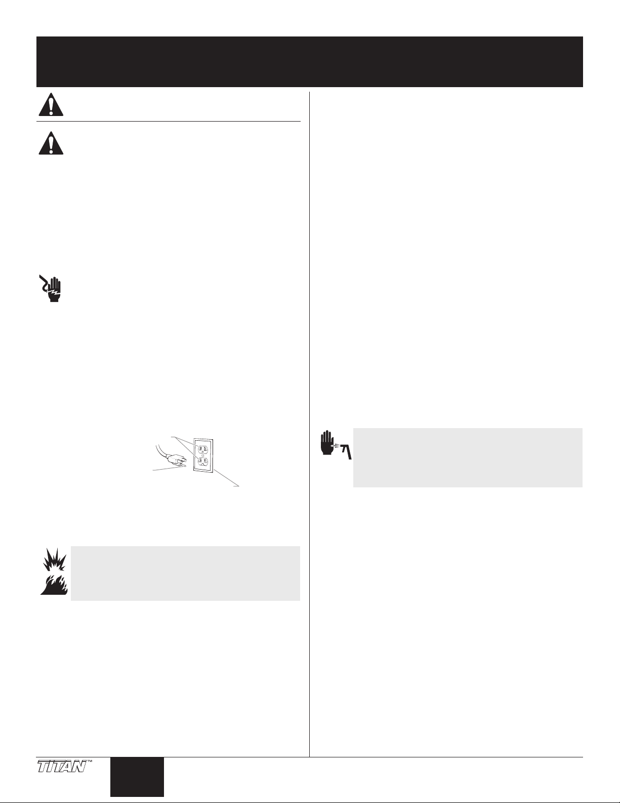
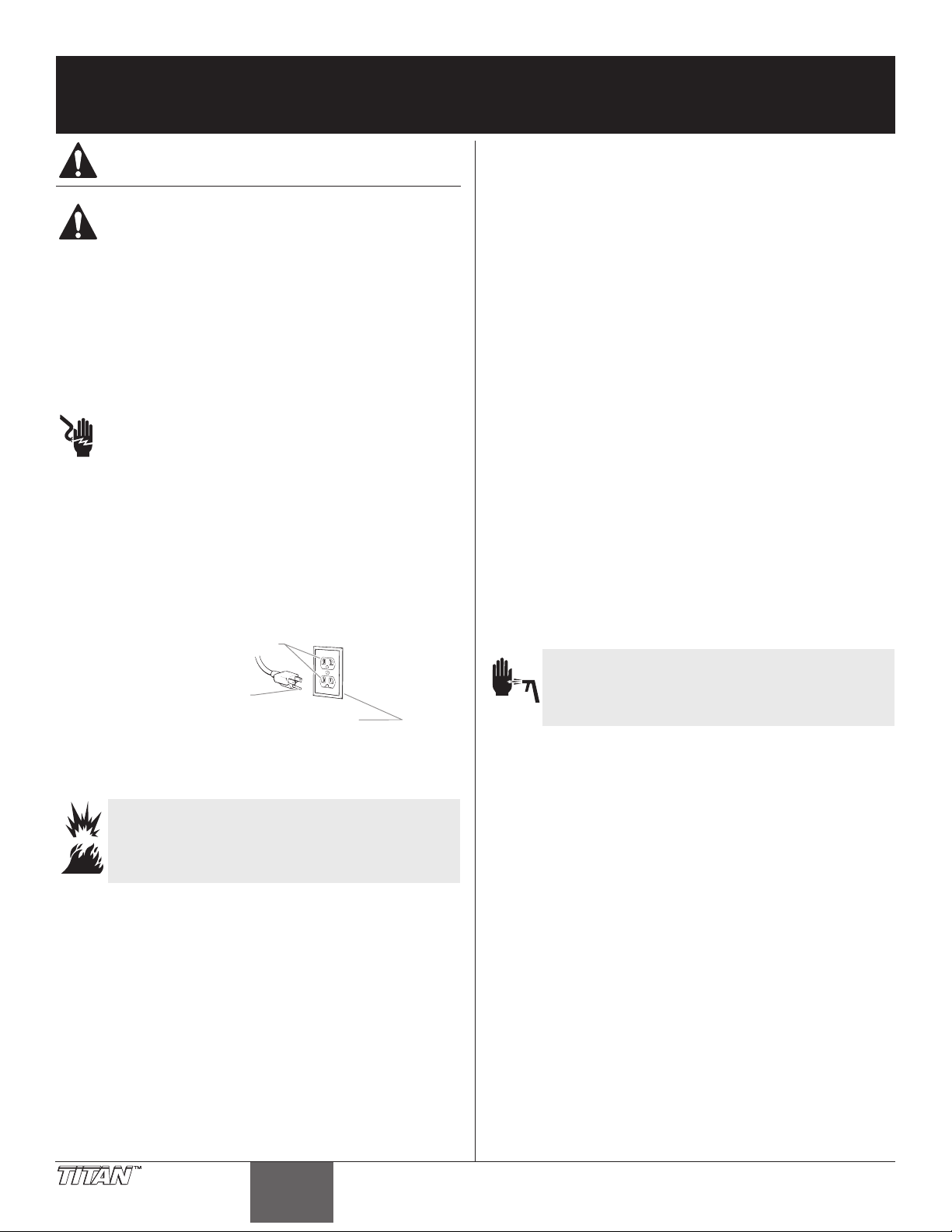
Grounded Outlet
Grounding Pin
Read all safety information before operating the
equipment. Save these instructions.
Indicates a hazardous situation which, if not avoided,
could result in death or serious injury.
To reduce the risks of re or explosion, electrical shock
and the injury to persons, read and understand all
instructions included in this manual. Be familiar with the
controls and proper usage of the equipment.
Grounding Instructions
This product must be grounded. In the event of an electrical short circuit,
grounding reduces the risk of electric shock by providing an escape wire
for the electric current. This product is equipped with a cord having a
grounding wire with an appropriate grounding plug. The plug must
be plugged into an outlet that is properly installed and grounded in
accordance with all local codes and ordinances.
WARNING - Improper installation of the grounding plug
can result in a risk of electric shock.
If repair or replacement of the cord or plug is necessary, do not connect
the green grounding wire to either at blade terminal. The wire with
insulation having a green outer surface with or without yellow stripes is
the grounding wire and must be connected to the grounding pin.
Check with a qualied electrician or serviceman if the grounding
instructions are not completely understood, or if you are in doubt as
to whether the product is properly grounded. Do not modify the plug
provided. If the plug will not t the outlet, have the proper outlet
installed by a qualied electrician.
This product is for use on a nominal 120 volt circuit and has a grounding
plug that looks like the plug illustrated below. Make sure that the product
is connected to an outlet having the same conguration as the plug. No
adapter should be used with this product.
conductive or grounded high-pressure airless paint sprayer hoses
specied by the manufacturer.
• Verify that all containers and collection systems are grounded to
prevent static discharge.
• Connect to a grounded outlet and use grounded extension cords
(electric models only). Do not use a 3 to 2 adapter.
• Do not use a paint or solvent containing halogenated
hydrocarbons. Such as chlorine, bleach mildewcide, methylene
chloride and trichloroethane. They are not compatible with
aluminum. Contact the coating supplier about compatibility of
material with aluminum.
• Keep spray area well ventilated. Keep a good supply of fresh air
moving through the area to keep the air within the spray area free
from accumulation of ammable vapors. Keep pump assembly in
well ventilated area. Do not spray pump assembly.
• Do not smoke in the spray area.
• Do not operate light switches, engines, or similar spark producing
products in the spray area.
• Keep area clean and free of paint or solvent containers, rags, and
other ammable materials.
• Know the contents of the paint and solvents being sprayed.
Read all Material Safety Data Sheets (MSDS) and container labels
provided with the paints and solvents. Follow the paint and
solvent manufacture’s safety instructions.
• Place pump at least 25 feet (7.62 meters) from the spray object in
a well ventilated area (add more hose if necessary). Flammable
vapors are often heavier than air. Floor area must be extremely
well ventilated. The pump contains arcing parts that emit sparks
and can ignite vapors.
• Plastic can cause static sparks. Never hang plastic to enclose spray
area. Do not use plastic drop cloths when spraying ammable
material.
• Fire extinguisher equipment shall be present and working.
Cover for grounded outlet box
IMPORTANT: When the sprayer is used with a generator
or uncontrolled line voltage, the use of Titan’s “Line Surge
Protector” (P/N 800-935) is recommended.
WARNING: EXPLOSION OR FIRE
Solvent and paint fumes can explode or ignite. Property
damage and/or severe injury can occur.
PREVENTION:
• Do not spray ammable or combustible materials near an open
ame, pilot lights or sources of ignition such as hot objects,
cigarettes, motors, electrical equipment and electrical appliances.
Avoid creating sparks from connecting and disconnecting power
cords.
• Use extreme caution when using materials with a ashpoint
below 100ºF (38ºC). Flashpoint is the temperature that a uid can
produce enough vapors to ignite.
• Paint or solvent owing through the equipment is able to result
in static electricity. Static electricity creates a risk of re or
explosion in the presence of paint or solvent fumes. All parts
of the spray system, including the pump, hose assembly, spray
gun and objects in and around the spray area shall be properly
grounded to protect against static discharge and sparks. Use only
WARNING: INJECTION INJURY
A high pressure paint stream produced by this equipment
can pierce the skin and underlying tissues, leading to
serious injury and possible amputation. See a physician
immediately.
PREVENTION:
• Do not aim the gun at, or spray any person or animal.
• Keep hands and other body parts away from the discharge. For
example, do not try to stop leaks with any part of the body.
• NEVER put your hand in front of the gun. Gloves will not provide
protection against an injection injury.
• ALWAYS keep the tip guard in place while spraying. The tip guard
provides some protection but is mainly a warning device.
• Only use a nozzle tip specied by the manufacturer.
• Use caution when cleaning and changing nozzle tips. In the
case where the nozzle tip clogs while spraying, ALWAYS lock
gun trigger, shut pump o, and release all pressure before
servicing, cleaning tip or guard, or changing tip. Pressure will
not be released by turning o the motor. The PRIME/SPRAY
valve or pressure bleed valve must be turned to their appropriate
positions to relieve system pressure. Refer to PRESSURE RELIEF
PROCEDURE described in the pump manual.
• Do not leave the unit energized or under pressure while
unattended. When the unit is not in use, turn o the unit and
relieve the pressure in accordance with the manufacturer’s
instructions.
• High-pressure spray is able to inject toxins into the body and
cause serious bodily injury. In the event that injection occurs,
seek medical attention immediately.
• Check hoses and parts for signs of damage, a leak can inject
material into the skin. Inspect hose before each use. Replace any
2 © Titan Tool Inc. All rights reserved.
English English
Page 3
Important Safety Information
damaged hoses or parts. Only use TITAN original-high-pressure
hoses in order to ensure functionality, safety and durability.
• This system is capable of producing 3000 PSI / 207 Bar. Only
use replacement parts or accessories that are specied by the
manufacturer and that are rated a minimum of 3000 PSI. This
includes spray tips, nozzle guards, guns, extensions, ttings, and
hose.
• Always engage the trigger lock when not spraying. Verify the
trigger lock is functioning properly.
• Verify that all connections are secure before operating the unit.
• Know how to stop the unit and bleed pressure quickly. Be
thoroughly familiar with the controls. Pressure will not be
released by turning o the motor. The PRIME/SPRAY valve
or pressure bleed valve must be turned to their appropriate
positions to relieve system pressure. Refer to PRESSURE RELIEF
PROCEDURE described in the pump manual.
• Always remove the spray tip before ushing or cleaning the
system.
NOTE TO PHYSICIAN:
Injection into the skin is a traumatic injury which can lead to
possible amputation. It is important to treat the injury as soon as
possible. DO NOT delay treatment to research toxicity. Toxicity
is a concern with some coatings injected directly into the blood
stream. Consultation with a plastic surgeon or reconstructive hand
surgeon may be advisable.
WARNING: HAZARDOUS VAPORS
Paints, solvents, insecticides, and other materials can
be harmful if inhaled or come in contact with the body.
Vapors can cause severe nausea, fainting, or poisoning.
PREVENTION:
• Use a respirator or mask if vapors can be inhaled. Read all
instructions supplied with the mask to be sure it will provide the
necessary protection.
• Wear protective eyewear.
• Wear protective clothing as required by coating manufacturer.
WARNING: GENERAL
Can cause severe injury or property damage.
PREVENTION:
• Always wear appropriate gloves, eye protection, clothing and a
respirator or mask when painting.
• Do not operate or spray near children. Keep children away from
equipment at all times.
• Do not overreach or stand on an unstable support. Keep eective
footing and balance at all times.
• Stay alert and watch what you are doing.
• Do not operate the unit when fatigued or under the inuence of
drugs or alcohol.
• Do not kink or over-bend the hose. Airless hose can develop leaks
from wear, kinking and abuse. A leak can inject material into the
skin.
• Do not expose the hose to temperatures or pressures in excess of
those specied by manufacturer.
• Do not use the hose as a strength member to pull or lift the
equipment.
• Use lowest possible pressure to ush equipment.
• Follow all appropriate local, state and national codes governing
ventilation, re prevention and operation.
• The United States Government Safety Standards have been
adopted under the Occupational Safety and Health Act (OSHA).
These standards, particularly part 1910 of the General Standards
and part 1926 of the Construction Standards should be consulted.
• Before each use, check all hoses for cuts, leaks, abrasion or
bulging of cover. Check for damage or movement of couplings.
Immediately replace hose if any of those conditions exist. Never
repair a paint hose. Replace with a conductive high-pressure
hose.
• Do not spray outdoors on windy days.
• Always unplug cord from outlet before working on equipment
(electric models only).
Specications
Gallons per minute (GPM) 0.47 (1.8 LPM)
Maximum tip size 0.021”
Maximum pressure 3000 PSI (20.7 MPa)
Power 0.75 HP DC motor, 120V, 60 Hz
Weight 27 lbs (12.2 kg)
Maximum hose length 100’ (30.5 m)
Generator requirement 5000 Watt, 20A, sine wave generator,
idle-down feature disabled
Table of Contents
Safety Precautions ........................................................................... 2
Specications ................................................................................... 3
General Description ........................................................................ 4
Operation ......................................................................................... 4
Locking the Spray Gun ...............................................................................4
Pressure Relief Procedure .......................................................................... 4
Setup ................................................................................................................. 5
Preparing a New Sprayer ........................................................................... 5
Preparing to Paint.........................................................................................5
Painting ............................................................................................................ 6
Spraying ........................................................................................... 6
Spraying Technique ..................................................................................... 6
Practice ............................................................................................................. 7
Clearing the Spray Tip ................................................................................. 7
Cleanup ............................................................................................ 8
Maintenance .................................................................................... 9
General Repair and Service Notes ..........................................................9
Replacing the Motor .................................................................................... 9
Replacing the Gears ...................................................................................10
Replacing the Pressure Switch / Transducer ....................................10
Replacing the Circuit Board ....................................................................11
Replacing the PRIME/SPRAY Valve .......................................................12
Replacing the Filters ..................................................................................12
Servicing the Fluid Section ......................................................................13
Troubleshooting ............................................................................ 15
Parts Listings .................................................................................. 44
Main Assembly ............................................................................................44
Skid Assembly ..............................................................................................45
Drive Assembly I ..........................................................................................46
Drive Assembly II ........................................................................................48
Siphon Assembly ........................................................................................50
Labels ..............................................................................................................51
Electrical Schematic....................................................................... 52
Product Registration ..................................................................... 53
Accessories ................................................................................54/55
Warranty ........................................................................................ 55
© Titan Tool Inc. All rights reserved. 3
Page 4
General Description
1
11
12
This airless sprayer is a precision power tool used for spraying
many types of materials. Read and follow this instruction manual
carefully for proper operating instructions, maintenance, and safety
information.
6
2
7
3
4
5
8
Operation
This equipment produces a fluid stream at extremely
high pressure. Read and understand the warnings
in the Safety Precautions section at the front of this
manual before operating this equipment.
IMPORTANT: The vents in the bottom and rear of the motor
shroud are designed to keep the motor from getting excessively
hot during operation. Make sure the vents in the bottom and
rear of the motor shroud are not covered or obstructed.
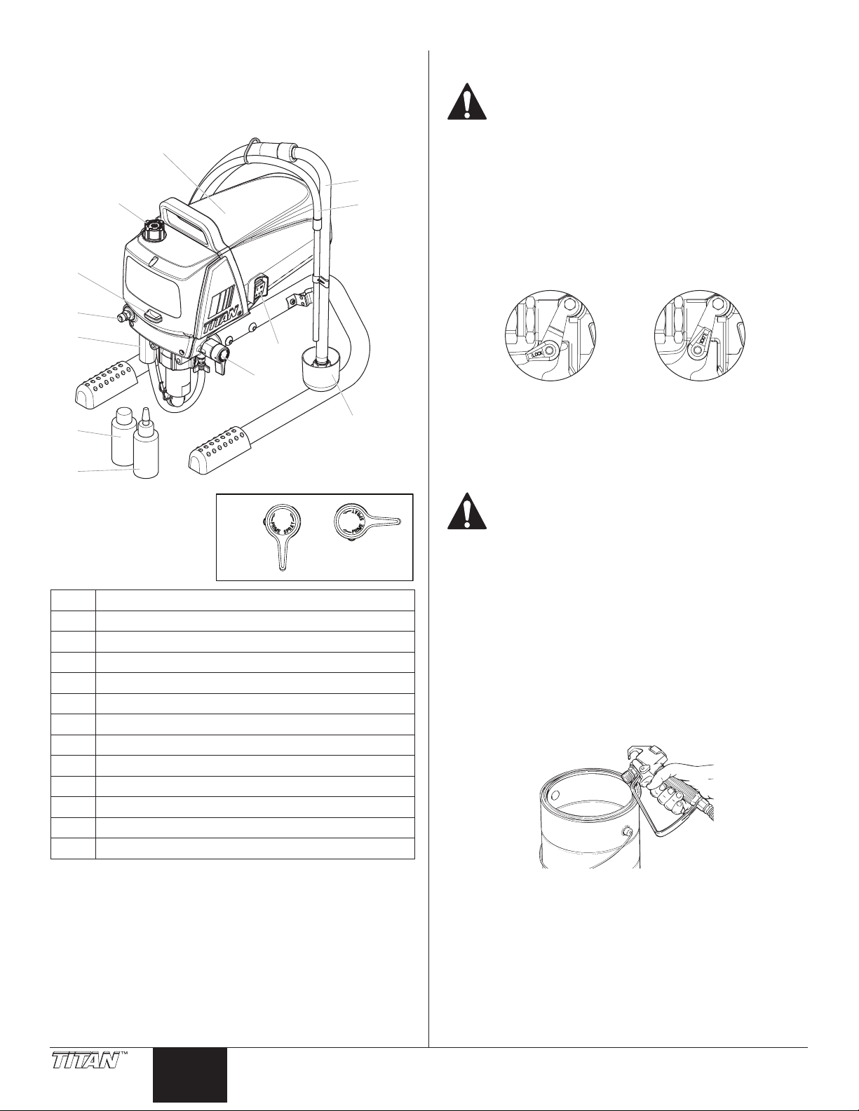
Locking the Spray Gun
1. To lock the trigger, rotate the trigger lock forward until it
stops.
2. To unlock the trigger, rotate the trigger lock backwards until it
is vertical.
Item Description
1 Motor
2 Pressure control knob
3 Oil cup
4 Outlet tting
5 Filter
6 Siphon tube
7 Return hose
8 ON/OFF switch
9 PRIME/SPRAY valve
10 Drip cup (stand model only)
11 Liquid Shield™ (4 oz.)
12 Piston Lube™ (4 oz.)
9*
k
PRIME
9*
10
SPRAY
p
Trigger locked (gun
will not spray)
Trigger unlocked
(gun will spray)
Pressure Relief Procedure
Be sure to follow the Pressure Relief Procedure when
shutting down the sprayer for any purpose, including
servicing or adjusting any part of the spray system,
changing or cleaning spray tips, or preparing for
cleanup.
1. Lock the gun by turning the gun trigger lock to the locked
position.
2. Move the PRIME/SPRAY valve down to the PRIME position.
3. Turn o the sprayer by moving the ON/OFF switch to the OFF
position.
4. Set the pressure to minimum by turning the pressure control
knob fully counterclockwise.
5. Unlock the gun by turning the gun trigger lock to the
unlocked position.
6. Hold the metal part of the gun rmly to the side of a metal
container to ground the gun and avoid a build up of static
electricity.
7. Trigger the gun to remove any pressure that may still be in the
hose.
8. Lock the gun by turning the gun trigger lock to the locked
position.
4 © Titan Tool Inc. All rights reserved.
English English
Page 5
Setup
Perform the following procedure before plugging in the power cord
of an electric unit.
1. Ensure that the siphon tube and the return hose are attached
and secure.
2. Using a wrench, attach a minimum of 50’ of 1/4” airless spray
hose to the outlet tting on the sprayer. Tighten securely.
3. Attach an airless spray gun to the spray hose. Using two
wrenches (one on the gun and one on the hose), tighten
securely.
NOTE: Do not attach the tip to the spray gun yet. Remove
the tip if it is already attached.
Make sure all airless hoses and spray guns are
electrically grounded and rated at or above the
maximum operating pressure range of the airless
sprayer.
4. Make sure the pressure control knob is turned fully
counterclockwise to its lowest pressure setting.
5. Make sure the ON/OFF switch is in its OFF position.
6. Fill the oil cup with approximately one tablespoon of Piston
Lube™ (see “Accessories” section, page 54).
IMPORTANT: Never operate unit for more than ten seconds
without fluid. Operating this unit without fluid will cause
unnecessary wear to the packings.
7. Make sure the electrical service is 120V, 15 amp minimum.
8. Plug the power cord into a properly grounded outlet at least
25’ from the spray area.
IMPORTANT: Always use a minimum 12 gauge, three-wire
extension cord with a grounded plug. Never remove the third
prong or use an adapter.
Preparing a New Sprayer
If this sprayer is new, it is shipped with test uid in the uid section to
prevent corrosion during shipment and storage. This uid must be
thoroughly cleaned out of the system with mineral spirits before you
begin spraying.
IMPORTANT: Always keep the trigger lock on the spray gun in
the locked position while preparing the system.
1. Place the siphon tube into a container of mineral spirits.
2. Place the return hose into a metal waste container.
3. Set the pressure to minimum by turning the pressure control
knob fully counterclockwise.
4. Move the PRIME/SPRAY valve down to the PRIME position.
5. Turn on the sprayer by moving the ON/OFF switch to the ON
position.
6. Allow the sprayer to run for 15–30 seconds to ush the
test uid out through the return hose and into the waste
container.
7. Turn o the sprayer by moving the ON/OFF switch to the OFF
position.
Preparing to Paint
Before painting, it is important to make sure that the uid in the
system is compatible with the paint that is going to be used.
NOTE: Incompatible uids and paint may cause the valves
to become stuck closed, which would require
disassembly and cleaning of the sprayer’s uid
section.
IMPORTANT: Always keep the trigger lock on the spray gun in
the locked position while preparing the system.
1. Place the siphon tube into a container of the appropriate
solvent. Examples of the appropriate solvent are water for
latex paint or mineral spirits for oil-based paints.
2. Place the return hose into a metal waste container.
3. Set the pressure to minimum by turning the pressure control
knob fully counterclockwise.
4. Move the PRIME/SPRAY valve down to the PRIME position.
NOTE: Hold the return hose in the waste container when
moving the PRIME/SPRAY valve to PRIME in case the
sprayer is pressurized.
5. Turn on the sprayer by moving the ON/OFF switch to the ON
position.
6. Allow the sprayer to run for 15–30 seconds to ush the old
solvent out through the return hose and into the metal waste
container.
7. Turn o the sprayer by moving the ON/OFF switch to the OFF
position.
NOTE: Make sure that the spray gun does not have a tip or
tip guard installed.
8. Move the PRIME/SPRAY valve up to the SPRAY position.
9. Turn on the sprayer.
10. Unlock the gun by turning the gun trigger lock to the
unlocked position.
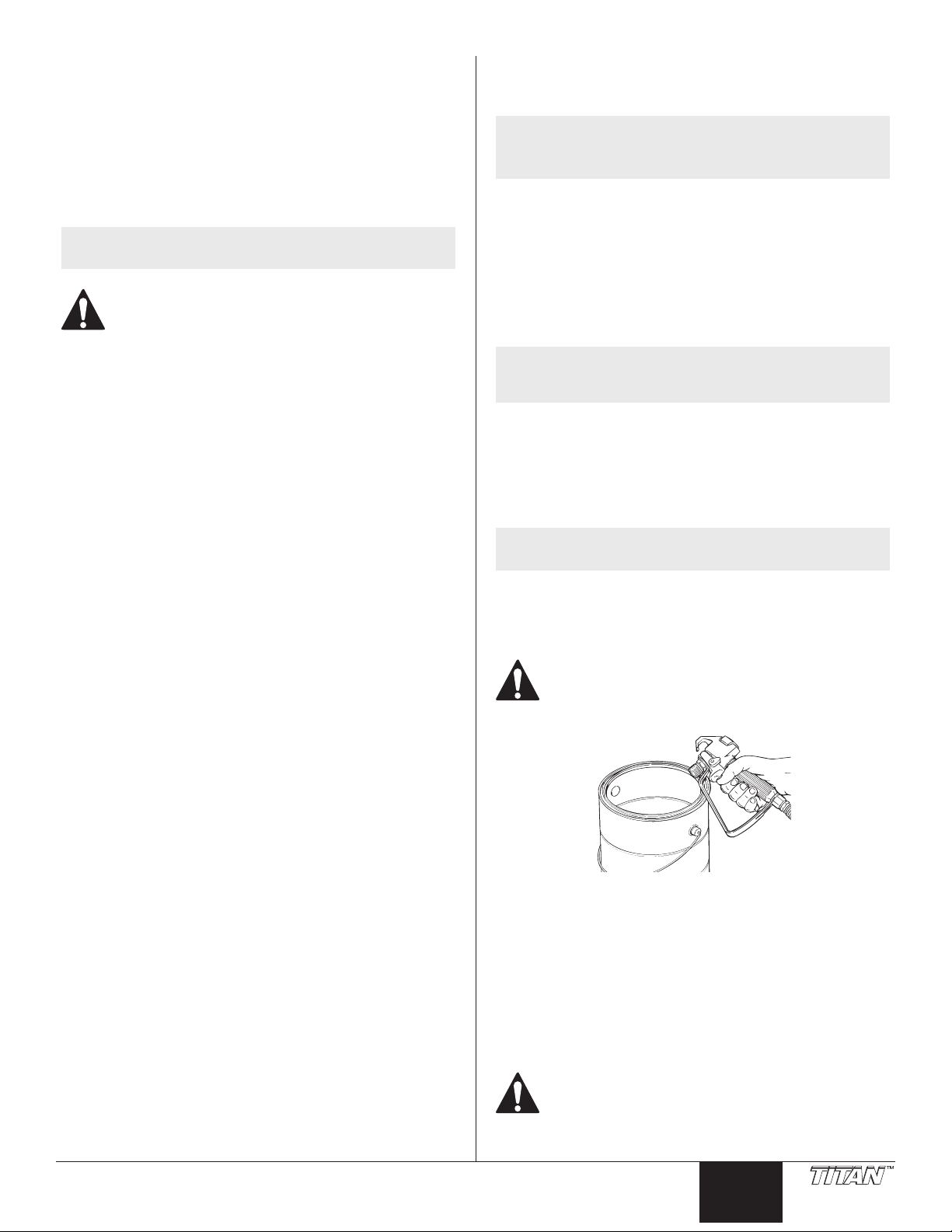
Ground the gun by holding it against the edge of the
metal container while flushing. Failure to do so may
lead to a static electric discharge, which may cause a
fire.
11. Trigger the gun into the metal waste container until the old
solvent is gone and fresh solvent is coming out of the gun.
12. Lock the gun by turning the gun trigger lock to the locked
position.
13. Set down the gun and increase the pressure by turning the
pressure control knob slowly clockwise.
14. Check the entire system for leaks. If leaks occur, follow the
“Pressure Relief Procedure” in this manual before tightening
any ttings or hoses.
15. Follow the “Pressure Relief Procedure” in this manual before
changing from solvent to paint.
© Titan Tool Inc. All rights reserved. 5
Be sure to follow the “Pressure Relief Procedure” when
shutting down the sprayer for any purpose, including
servicing or adjusting any part of the spray system,
changing or cleaning spray tips, or preparing for
cleanup.
Page 6
Painting
Keep stroke smooth and at an even speed.
Even coat throughout
Heavy Coat
Do not ex wrist while spraying.
Light Coat Light Coat
Approximately
1. Place the siphon tube into a container of paint.
2. Place the return hose into a metal waste container.
3. Set the pressure to minimum by turning the pressure control
knob fully counterclockwise.
4. Move the PRIME/SPRAY valve down to the PRIME position.
5. Turn on the sprayer by moving the ON/OFF switch to the ON
position.
6. Allow the sprayer to run until paint is coming through the
return hose into the metal waste container.
7. Turn o the sprayer by moving the ON/OFF switch to the OFF
position.
8. Remove the return hose from the waste container and place it
in its operating position into the container of paint.
9. Move the PRIME/SPRAY valve up to the SPRAY position.
10. Turn on the sprayer.
11. Unlock the gun by turning the gun trigger lock to the
unlocked position.
Ground the gun by holding it against the edge of the
metal container while flushing. Failure to do so may
lead to a static electric discharge, which may cause a
fire.
12. Trigger the gun into the metal waste container until all air and
solvent is ushed from the spray hose and paint is owing
freely from the gun.
13. Lock the gun by turning the gun trigger lock to the locked
position.
14. Turn o the sprayer.
15. Attach tip guard and tip to the gun as instructed by the tip
guard or tip manuals.
Spraying
POSSIBLE INJECTION HAZARD. Do not spray without
the tip guard in place. Never trigger the gun unless
the tip is in either the spray or the unclog position.
Always engage the gun trigger lock before removing,
replacing, or cleaning tip.
Spraying Technique
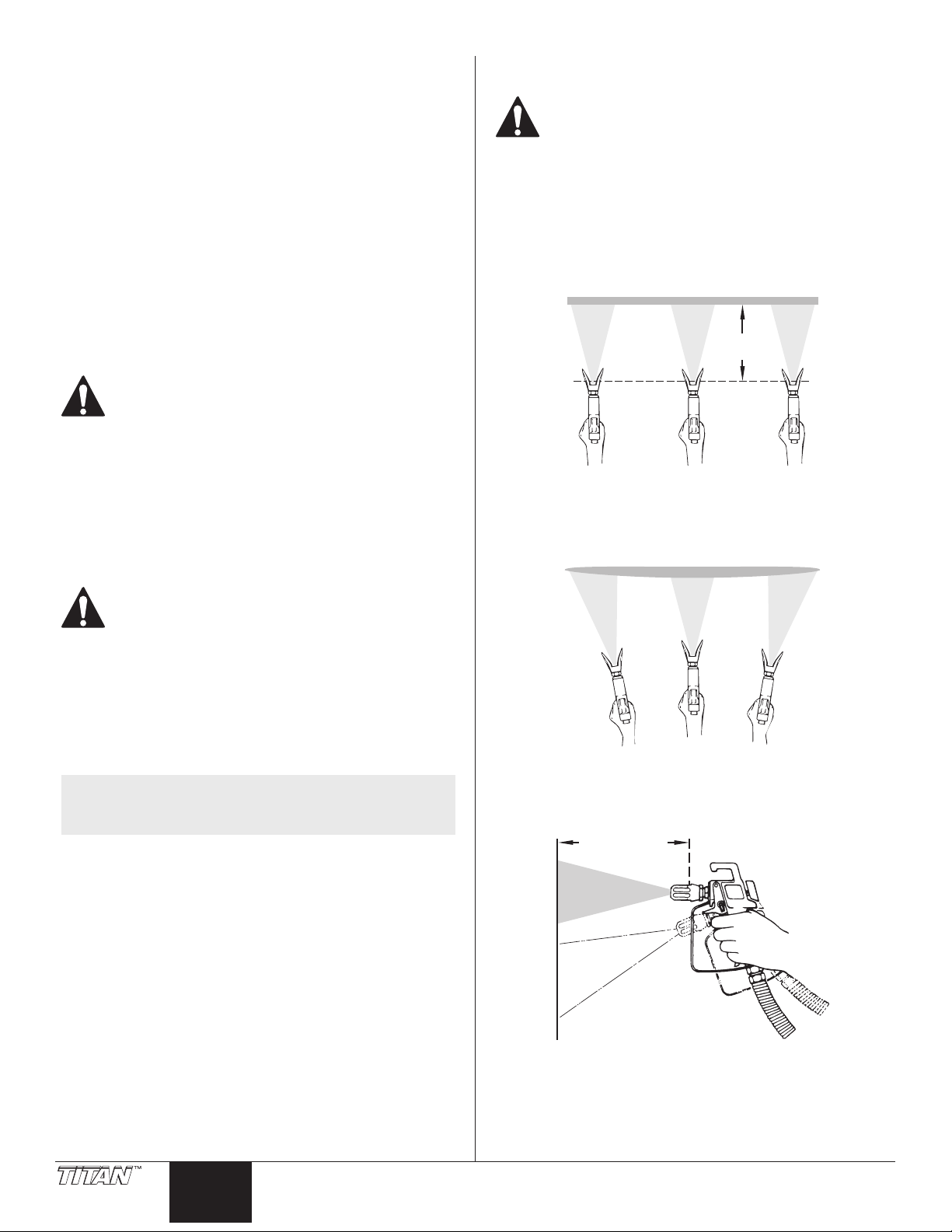
The key to a good paint job is an even coating over the entire surface.
This is done by using even strokes. Keep your arm moving at a
constant speed and keep the spray gun at a constant distance from
the surface. The best spraying distance is 10 to 12 inches between
the spray tip and the surface.
Approximately
10 to 12 inches
Keep the spray gun at right angles to the surface. This means moving
your entire arm back and forth rather than just exing your wrist.
POSSIBLE INJECTION HAZARD. Do not spray without
the tip guard in place. Never trigger the gun unless
the tip is in either the spray or the unclog position.
Always engage the gun trigger lock before removing,
replacing or cleaning tip.
16. Turn on the sprayer.
17. Increase the pressure by turning the pressure control knob
slowly clockwise and test the spray pattern on a piece of
cardboard. Adjust the pressure control knob until the
spray from the gun is completely atomized. Try to keep the
pressure control knob at the lowest setting that maintains
good atomization.
NOTE: Turning the pressure up higher than needed to
atomize the paint will cause premature tip wear and
additional overspray.
Keep the spray gun perpendicular to the surface, otherwise one end
of the pattern will be thicker than the other.
10 to 12 inches
Right way
Wrong way
6 © Titan Tool Inc. All rights reserved.
English English
Page 7
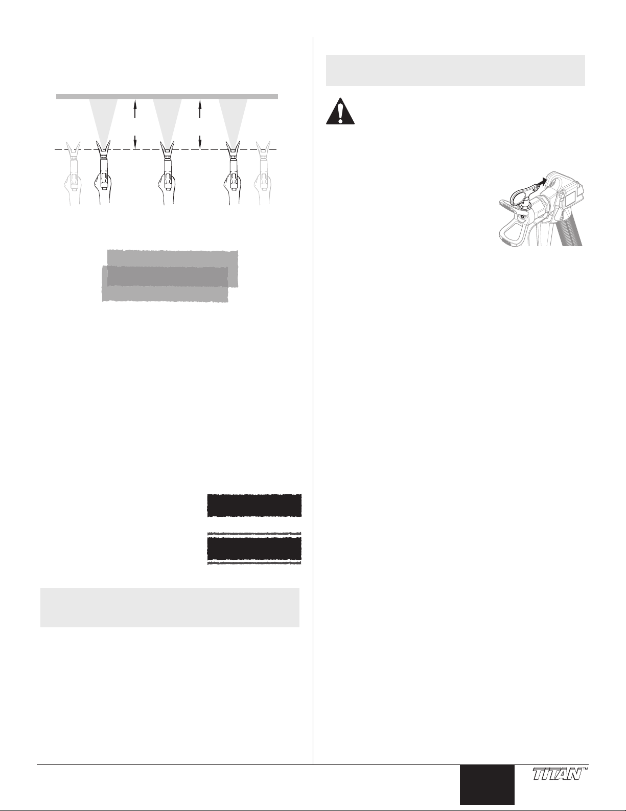
The spray gun should be triggered by turning it on and o with each
Proper way to trigger the spray gun
Start stroke End strokePull trigger Release triggerKeep steady
stroke. This will save paint and avoid paint buildup at the end of the
stroke. Do not trigger the gun during the middle of a stroke. This will
result in an uneven spray and splotchy coverage.
Keep stroke
even
Approximately
10 to 12 inches
Overlap each stroke by about 50%. This will ensure an even coating.
50% Overlap
When you stop painting, lock the gun trigger lock, turn the pressure
control knob counterclockwise to its lowest setting and set the
PRIME/SPRAY valve to PRIME. Turn the ON/OFF switch to the OFF
position and unplug the sprayer.
Clearing the Spray Tip
NOTE: If your spray pattern becomes distorted or stops
completely during spraying, follow these steps.
The flow from the spray tip is at very high pressure.
Contact with any body part may be dangerous. Do not
place finger on gun outlet. Do not point the gun at
any person. Never operate the spray gun without the
proper tip guard.
1. Follow the “Pressure Relief Procedure” found in the Operation
section of this manual.
2. If the tip clogs, rotate the tip
handle 180º until the arrow on the
handle is facing the opposite of
the spray direction and the handle
stops in the reverse position.
3. Trigger the gun once into a waste
container so that the pressure
can blow the clog out. NEVER use
the tip in the reverse position for
more than ONE trigger pull at a time. This procedure can be
repeated until the tip is free of clogging.
Practice
1. Be sure that the paint hose is free of kinks and clear of objects
with sharp cutting edges.
3. Set the pressure to minimum by turning the pressure control
knob fully counterclockwise.
3. Move the PRIME/SPRAY valve up to its SPRAY position.
4. Turn the pressure control knob clockwise to its highest
setting. The paint hose should stien as paint begins to ow
through it.
5. Unlock the gun trigger lock.
6. Trigger the spray gun to bleed air out of the hose.
7. When paint reaches the spray tip,
spray a test area to check the spray
pattern.
8. Use the lowest pressure setting
necessary to get a good spray
pattern. If the pressure is set too
low, tailing will appear or the paint
will spatter out in gobs rather than
in a ne spray.
NOTE: Turning the pressure up higher than needed to
atomize the paint will cause premature tip wear and
additional overspray.
Good spray pattern
Paint tailing pattern
© Titan Tool Inc. All rights reserved. 7
Page 8
Cleanup
Special cleanup instructions for use with flammable
solvents:
• Always ush spray gun preferably outside and at least one
hose length from spray pump.
• If collecting ushed solvents in a one gallon metal container,
place it into an empty ve gallon container, then ush
solvents.
• Area must be free of ammable vapors.
• Follow all cleanup instructions.
Always spray at minimum pressure with the gun
nozzle tip removed when using mineral spirits or any
other solvent to clean the sprayer, hose, or gun. Static
electricity buildup may result in a re or explosion in
the presence of ammable vapors.
IMPORTANT: The sprayer, hose, and gun should be cleaned
thoroughly after daily use. Failure to do so permits material to
build up, seriously affecting the performance of the unit.
1. Follow the “Pressure Relief Procedure” found in the Operation
section of this manual.
2. Remove the gun tip and tip guard and clean with a brush
using the appropriate solvent.
3. Place the siphon tube into a container of the appropriate
solvent. Examples of the appropriate solvent are water for
latex paint or mineral spirits for oil-based paints.
4. Place the return hose into a metal waste container.
5. Set the pressure to minimum by turning the pressure control
knob fully counterclockwise.
6. Move the PRIME/SPRAY valve down to its PRIME position.
16. Turning clockwise, unscrew the lter (2) from the pump
manifold (3).
NOTE: Left-handed threads require turning the lter
clockwise to remove.
17. Make sure the lter seal (4) is in position.
18. Turning counterclockwise, screw the new or cleaned lter into
the pump manifold.
19. Clean the inside of the lter housing using the appropriate
cleaning solution.
20. Slide the lter housing over the lter and thread it into the
pump manifold until secure.
3
1
4
2
21. Unplug the unit and store in a clean, dry area.
IMPORTANT: Do not store the unit under pressure.
NOTE: Hold the return hose in the waste container when
7. Turn on the sprayer by moving the ON/OFF switch to the ON
8. Allow the solvent to circulate through the unit and ush the
9. Turn o the sprayer by moving the ON/OFF switch to the OFF
10. Move the PRIME/SPRAY valve up to its SPRAY position.
11. Turn on the sprayer.
12. Trigger the gun into the metal waste container until the paint
13. Continue to trigger the spray gun into the waste container
NOTE: For long-term or cold weather storage, pump
For short-term storage when using latex paint,
moving the PRIME/SPRAY valve to PRIME in case the
sprayer is pressurized.
position.
paint out of the return hose into the metal waste container.
position.
Ground the gun by holding it against the edge of the
metal container while flushing. Failure to do so may
lead to a static electric discharge, which may cause a
fire.
is ushed out of the hose and solvent is coming out of the
gun.
until the solvent coming out of the gun is clean.
mineral sprits through the entire system.
pump water mixed with Titan Liquid Shield through
the entire system (see the Accessories section of this
manual for part number).
14. Follow the “Pressure Relief Procedure” found in the Operation
section of this manual.
15. Loosen and remove the lter housing (1).
8 © Titan Tool Inc. All rights reserved.
English English
Page 9
Maintenance
Replacing the Motor
Before proceeding, follow the “Pressure Relief
Procedure” outlined previously in this manual.
Additionally, follow all other warnings to reduce the
risk of an injection injury, injury from moving parts
or electric shock. Always unplug the sprayer before
servicing!
General Repair and Service Notes
The following tools are needed when repairing this sprayer:
Phillips Screwdriver 3/8” Hex Wrench
Needle Nose Pliers 5/16” Hex Wrench
Adjustable Wrench 1/4” Hex Wrench
Rubber Mallet 3/16” Hex Wrench
Flat-blade Screwdriver 5/32” Hex Wrench
Torque wrench (in.-lbs.) Resistance multi-meter
Pressure gauge (P/N 0508239)
1. Before repairing any part of the sprayer, read the instructions
carefully, including all warnings.
IMPORTANT: Never pull on a wire to disconnect it. Pulling on a
wire could loosen the connector from the wire.
2. Test your repair before regular operation of the sprayer to be
sure that the problem is corrected. If the sprayer does not
operate properly, review the repair procedure to determine if
everything was done correctly. Refer to the Troubleshooting
Charts to help identify other possible problems.
3. Make certain that the service area is well ventilated in case
solvents are used during cleaning. Always wear protective
eyewear while servicing. Additional protective equipment
may be required depending on the type of cleaning solvent.
Always contact the supplier of solvents for recommendations.
4. If you have any further questions concerning your Titan Airless
Sprayer, call Titan:
Customer Service ................................................ 1-800-526-5362
Fax ................................................................. 1-800-528-4826
NOTE: It is recommended that the following procedure be
performed by a Titan Authorized Service Center.
1. Perform the “Pressure Relief Procedure” and unplug the
sprayer.
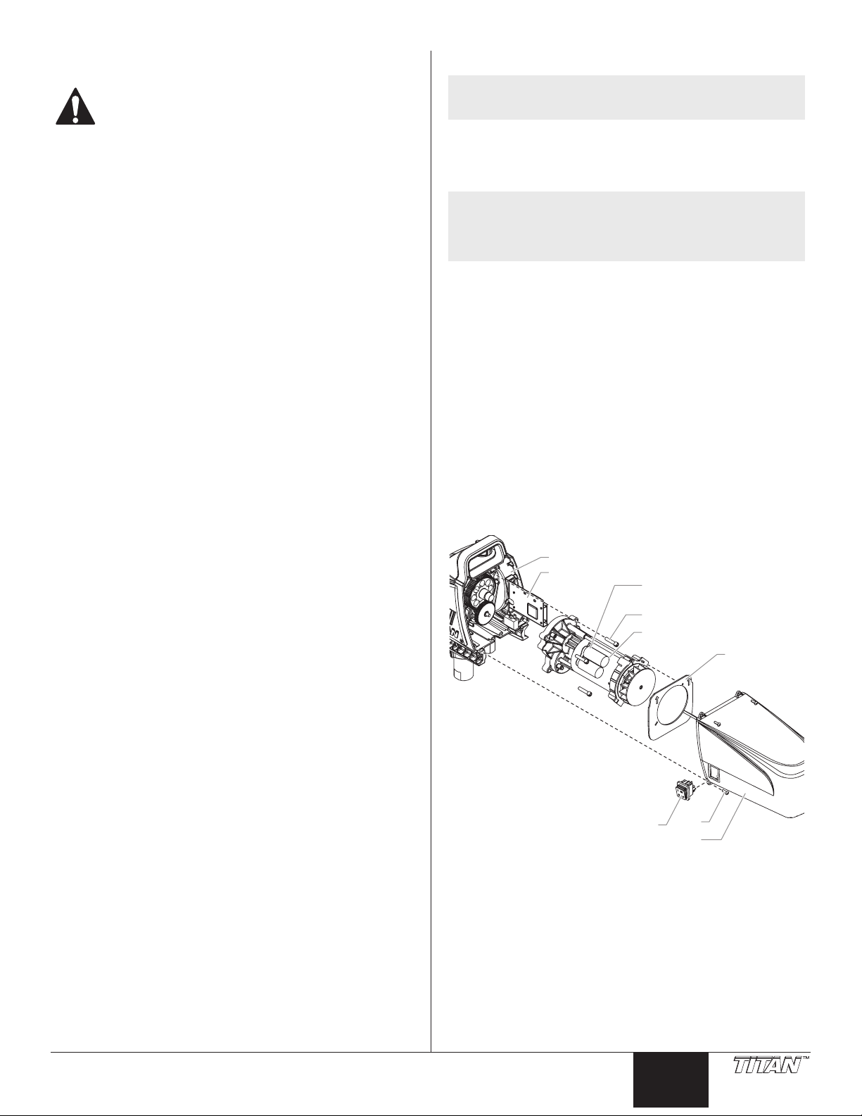
2. Loosen and remove the four motor cover screws (1). Remove
the motor cover (2).
NOTE: The ON / OFF switch (3) is housed inside the
motor cover. In order to remove the motor cover
completely, you must disconnect all of the wires at
the rear of the switch. Note the position of the wires
before disconnecting.
3. On the back of the motor (4), disconnect the two wires (black
and red) coming from the circuit board (5). Remove the
ground wire from the motor housing.
4. Slide the motor bae (7) o the rear of the motor.
5. Loosen and remove the four motor mounting screws (8).
6. Pull the motor (4) out of the pump housing (9).
7. With the motor removed, inspect the gears in the pump
housing (9) for damage or excessive wear. Replace the gears,
if necessary.
8. Install the new motor (4) into the pump housing (9).
9. Secure the motor with the four motor mounting screws (8).
10. Reconnect the wires (refer to the electrical schematic in the
Parts List section of this manual).
11. Slide the motor bae (7) onto the rear of the motor. The
arrows on the bae should be pointed up.
12. Slide the motor cover (2) over the motor. Secure the motor
cover with the four motor cover screws (1).
9
5
6
8
4
7
© Titan Tool Inc. All rights reserved. 9
3
1
2
Page 10
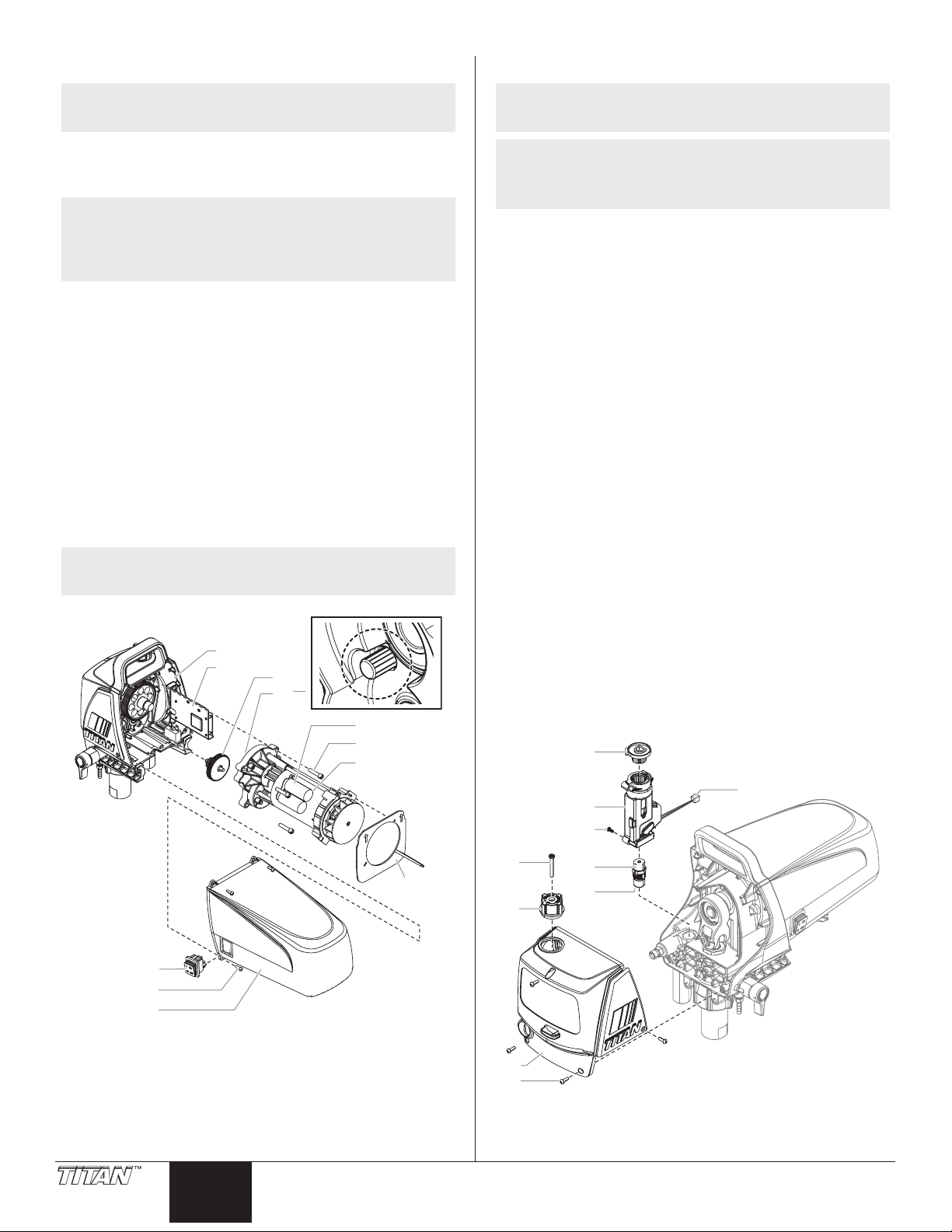
Replacing the Gears
2
3
4
Replacing the Pressure Switch / Transducer
NOTE: It is recommended that the following procedure be
1. Perform the Pressure Relief Procedure and unplug the sprayer.
2. Loosen and remove the four motor cover screws (1). Remove
NOTE: The ON / OFF switch (3) is housed inside the
3. On the back of the motor (4), disconnect the two wires (black
4. Slide the motor bae (7) o the rear of the motor.
5. Loosen and remove the four motor mounting screws (8).
6. Pull the motor (4) out of the pump housing (9).
7. Inspect the armature gear (10) on the end of the motor for
8. Remove and inspect the 2nd stage gear (11) for damage or
9. If the armature gear (10) or 2nd stage gear (11) are damaged,
10. Reassemble the pump by reversing the above steps.
NOTE: Rell the gear box in the pump housing with ve
performed by a Titan Authorized Service Center.
the motor cover (2).
motor cover. In order to remove the motor cover
completely, you must disconnect all of the wires at
the rear of the switch. Note the position of the wires
before disconnecting.
and red) coming from the circuit board (5). Remove the
ground wire from the motor housing.
damage or excessive wear. If this gear is completely worn out,
replace the entire motor.
excessive wear. Replace if necessary.
the pump housing (9) must be cleaned of any debris caused
by damaged gears.
ounces of Lubriplate™ grease (P/N 314-171).
9
5
11
10
6
8
4
NOTE: It is recommended that the following procedure be
performed by a Titan Authorized Service Center.
NOTE: If the sprayer loses all pressure adjustment, or there
is paint leakage from the front of the sprayer, the
pressure switch and/or transducer may need to be
replaced.
1. Perform the Pressure Relief Procedure and unplug the sprayer.
2. Remove the screw (1) that secures the pressure control knob
(2) to the bottom of the pressure control knob (3). Remove
the knob (2).
3. Loosen and remove the three front cover screws (4). Remove
the front cover (5).
4. Remove the screw (7) from the side of the pressure switch.
Remove the bottom of the pressure control knob (3) from the
top of the pressure switch.
5. Remove the pressure switch assembly (6) from the top of the
transducer (8).
6. Unplug the pressure switch (6) from the wire connector (10).
IMPORTANT: Do not attempt to pull wires from the inside of the
pressure switch assembly. If the pressure switch wire connector
(10) is not exposed through the opening in the pump housing,
pull gently on the wires until the connector is shown through the
opening.
7. Check pressure switch continuity at the connector. If the
switch is bad replace with a new pressure switch assembly.
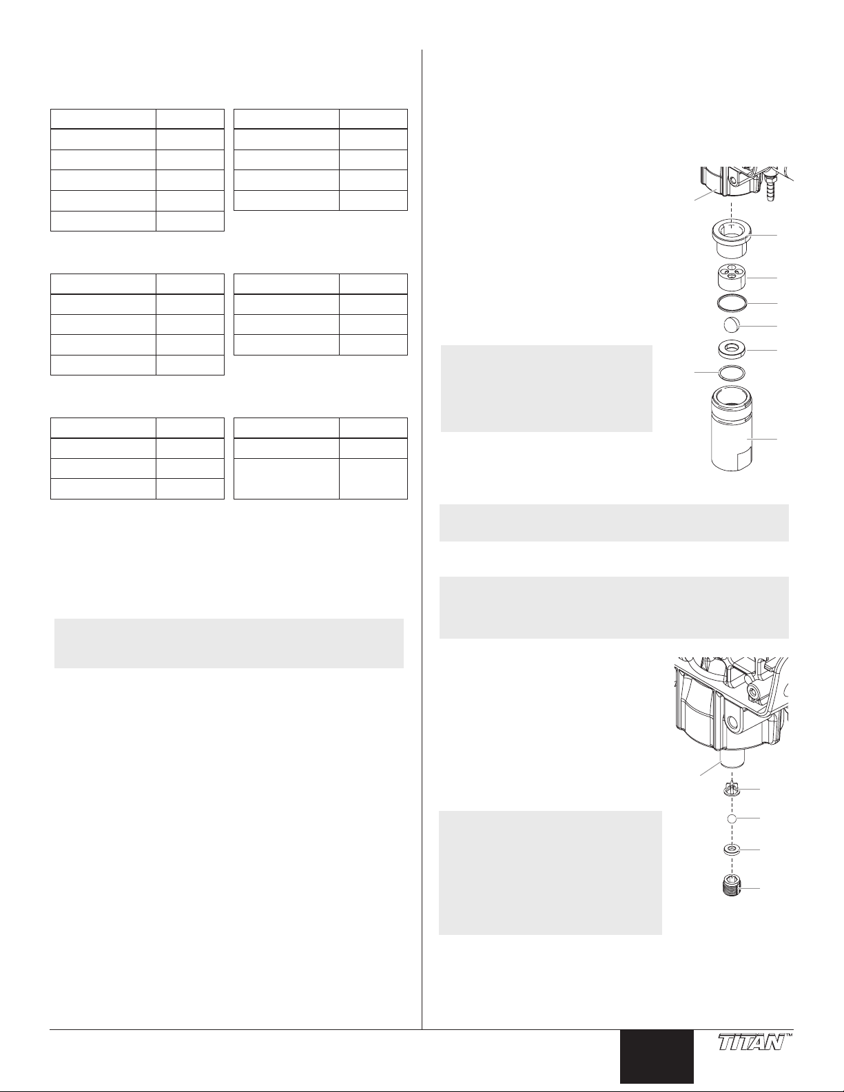
8. Inspect the transducer (8) for the presence of paint. If there is
paint, replace the transducer. If there is no paint, skip to step
9, below.
a. Using a wrench on the hex head of the transducer, loosen and
remove the transducer assembly.
b. Apply a generous amount of grease to the transducer O-ring (9).
Reinstall the transducer assembly and torque to 70-75 in-lbs.
9. Reconnect the pressure switch wires (refer to the electrical
schematic in the Parts List section of this manual).
10. Push pressure switch assembly (6) back onto the transducer
until it bottoms out on the transducer hex head.
11. Replace the screw (7) into the side of the pressure switch.
12. See “Resetting the Pressure Switch Timing”, next page.
6
7
1
3
1
10 © Titan Tool Inc. All rights reserved.
English English
7
2
5
8
9
10
Page 11
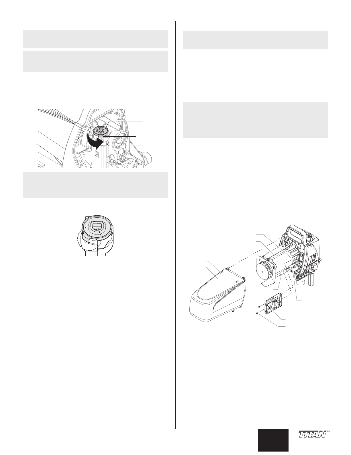
Resetting the Pressure Switch Timing
8
Replacing the Circuit Board
NOTE: It is recommended that the following procedure be
performed by a Titan Authorized Service Center.
NOTE: The components of the pressure switch must be
properly reassembled and adjusted in order for the
pump to operate at the correct maximum pressure.
Perform this procedure using pressure gauge P/N 0508239.
1. Make sure the knob bottom (1) is installed in the pressure
switch (2).
2. Viewing from the top, turn the knob bottom (1) counter-
clockwise as far as the teeth inside the pressure switch will allow.
1
3
2
NOTE: If the stop (3) on the pressure switch prevents the
knob bottom from continuing to turn, remove the
knob bottom, re-orient it on the teeth and continue
to turn it counterclockwise until it stops.
3. Re-orient the knob tab against the pressure switch tab stop.
NOTE: It is recommended that the following procedure be
performed by a Titan Authorized Service Center.
Perform this procedure using Circuit Board Kit P/N 0532208A.
1. Perform the Pressure Relief Procedure and unplug the sprayer.
2. Loosen and remove the four motor cover screws (1). Remove
the motor cover (2).
3. Disconnect the red and black wires that connect the circuit
board (3) to the motor assembly (4).
4. Disconnect the white wires that connect the circuit board to
the pressure switch.
NOTE: The pressure switch will not be visible as it is
located on the other side of the motor housing. The
white wires will be visible through an opening in
the housing (5). If the wire connector is not visible,
gently pull the wires through the opening until the
connector is accessible.
5. Disconnect the black wire that connects the circuit board to
the circuit breaker (6).
6. Disconnect the white wire that connects the circuit board to
the power switch (7).
7. Loosen and remove the two circuit board screws (8). Remove
the circuit board (3).
8. Install the new circuit board (3) and secure with the two circuit
board screws (8).
9. Reconnect the wires that were disconnected in steps 3-6
(refer to the electrical schematic in the Parts List section of this
manual).
10. Slide the motor cover over the motor. Secure the motor cover
with the four motor cover screws.
4. Replace the front cover and secure with the three screws.
5. Replace the pressure control knob into the knob bottom but
do not secure with the screw. Turn the knob fully clockwise to
maximum.
6. Connect the pressure gauge to the outlet tting.
7. Connect a high-pressure hose and gun to the pressure gauge.
8. Using water as a media, follow the steps in the “Painting”
section. It is not necessary to attach a spray tip to the gun.
Leave the pressure set to maximum.
9. The sprayer should now be pressurized at maximum pressure.
The pressure gauge should be reading between 2800-3000
PSI.
10. If the pressure reading is below or above this reading, the
set screw down inside the pressure switch will have to be
adjusted. Adjust it per the guidelines below using a long hex
wrench.
a. If the pressure reading is below 2800 PSI, turn the set screw
counterclockwise until the pressure gauge reads between 28003000 PSI.
b. If the pressure reading is above 3000 PSI, relieve pressure by
turning the PRIME/SPRAY knob to PRIME. While the sprayer is
circulating, turn the set screw clockwise slightly and then turn
the PRIME/SPRAY knob to SPRAY. Repeat this until the pressure
reading decreases to a range of 2800-3000 PSI.
11. When the pressure gauge reads between 2800-3000 PSI, the
pressure control knob is now set. Secure the pressure control
knob with the pressure control knob screw.
5
4
1
2
7
6
3
© Titan Tool Inc. All rights reserved. 11
Page 12
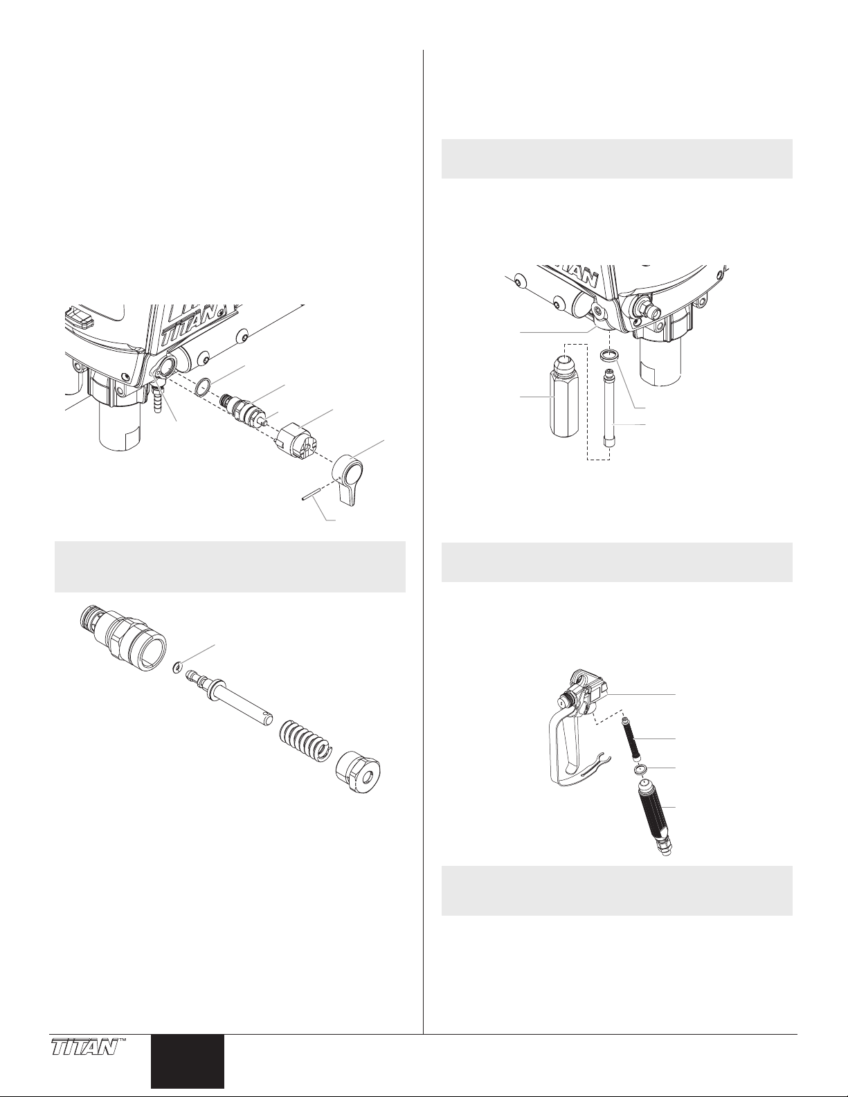
Replacing the PRIME/SPRAY Valve
1
2
1
4
3
2
Perform the following procedure using PRIME/SPRAY valve
replacement kit P/N 700-258.
1. Push the groove pin (1) out of the valve handle (2).
2. Remove the valve handle (2) and the cam base (3).
3. Using a wrench, loosen and remove the valve housing
assembly (4).
4. Make sure the gasket (5) is in place and thread the new valve
housing assembly into the pump block (6). Tighten securely
with wrench.
5. Place the cam base (3) over the valve housing assembly (4).
Lubricate the cam base with grease and line up the cam with
the pump block (6).
6. Line up the hole on the valve stem (7) with the hole in the
valve handle (2).
7. Insert the groove pin into the valve handle and through the
valve stem to secure the valve handle in position.
5
4
7
3
6
Replacing the Filters
Pump Filter
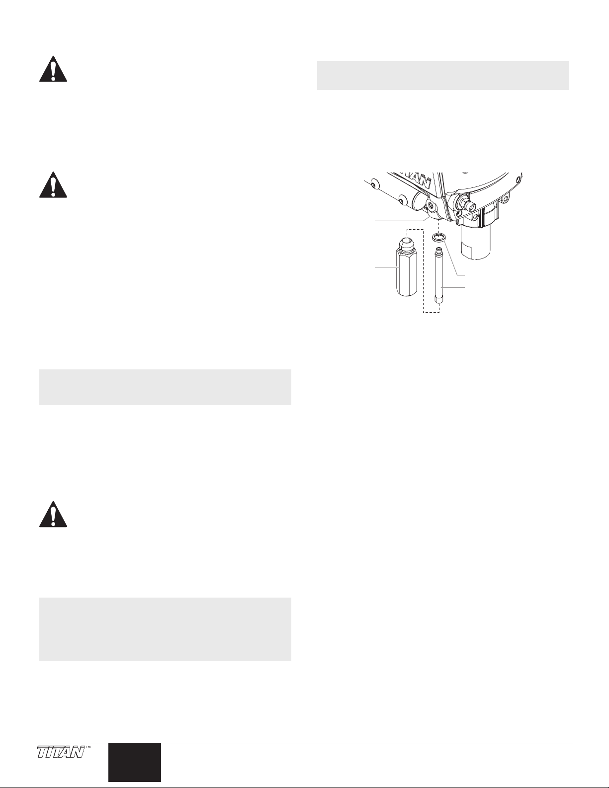
1. Loosen and remove the lter housing (1).
2. Turning clockwise, unscrew the lter (2) from the pump
manifold (3).
NOTE: Left-handed threads require turning the lter
clockwise to remove.
3. Make sure the lter seal (4) is in position.
4. Turning counterclockwise, screw the new or cleaned lter into
the pump manifold.
5. Slide the lter housing over the lter and thread it into the
pump manifold until secure.
3
1
4
2
NOTE: When using “HOT” solvents, replace Viton o-ring
(item 8) with optional PTFE o-ring (700-897). Install
with o-ring tool (700-890).
8
Gun Filter
1. Move the gun trigger lock to the unlocked position.
2. Loosen and remove the handle (1) from the gun body (2).
3. Turning clockwise, unscrew the lter (3) from the gun body.
NOTE: Left-handed threads require turning the lter
clockwise to remove.
4. Turning counterclockwise, screw the new or cleaned lter into
the gun body.
5. Make sure the handle seal (4) is in position and thread the
handle into the gun body until secure.
6. Move the gun trigger lock to the locked position.
NOTE: For more detail, part number information, and
12 © Titan Tool Inc. All rights reserved.
English
complete assembly drawings, please see the gun
owner’s manual.
Page 13
Servicing the Fluid Section
Three standard repair kits are available to repair the uid section:
Packing Kit P/N 0532911 Includes:
Item Part # Item Part #
Upper bushing 0532215 Inlet ball 700-821
Upper packing 0532914 Outlet valve ball 50164
Lower packing 0532915 Outlet valve cage 0516304
Inlet valve seal 700-821 Crush washer 704-612
O-ring, PTFE 762-058
Valve Seat Kit P/N 0532916 Includes:
Item Part # Item Part #
Inlet valve seat 0532345 Outlet valve seat 0512343
Inlet valve seal 700-821 Outlet valve ball 50164
Inlet valve ball 762-145 Outlet valve cage 0516304
O-ring, PTFE 762-058
Piston Assembly Kit P/N 0532204A Includes:
Item Part # Item Part #
Piston rod ------- Outlet valve seat 0512343
Upper cage 0516304 Outlet valve
Outlet valve ball 50164
retainer
0512342
Servicing the Valves
The design of the uid section allows access to the foot valve
and seat as well as the outlet valve and seat without completely
disassembling the uid section. It is possible that the valves may not
seat properly because of debris stuck in the foot valve seat or outlet
valve seat. Use the following instructions to clean the valves and
replace the seats.
Servicing the Inlet Valve
1. Using a wrench, loosen and remove
the inlet valve housing (1) from the
pump housing (2).
2. Remove the piston bushing (7),
cage (6), seal (5), ball (4) and inlet
valve seat (3).
3. Remove the O-ring (8) from inside
the inlet valve housing.
4. Clean out any debris in the inlet
valve housing (1) and examine the
valve housing and seat (3). If the
seat is damaged, replace the seat
and ball.
NOTE: When replacing the seat,
make sure the notched
side of the seat is facing
down when reinstalled
into the inlet valve
assembly.
5. Reinstall all parts back into the inlet
valve housing. The valve seat kit
includes a new O-ring (8), seat (3)
ball (4) and seal (5).
2
8
7
6
5
4
3
1
To service the uid section of the pump, use all the parts supplied by
either one or all of these kits.
When using the standard repair kits listed above, use the following
procedures to service the valves and repack the uid section. Perform
the following steps before performing any maintenance on the uid
section.
NOTE: Some optional service kits are available for this
sprayer and are listed in the “Accessories” section of
this manual (page 54).
1. Remove the screw that secures the pressure control knob.
Remove the knob.
2. Loosen and remove the three front cover screws. Remove the
front cover.
3. Rotate the pump shaft so the piston is in the bottom dead
center position. This can be done by moving the yoke. This is
required to disassemble all the parts.
4. For Upright Cart units, remove the return hose from the hose
clip on the siphon tube. Unscrew the siphon tube from the
inlet valve housing.
5. For Stand units, remove the retaining ring from the bottom
of the inlet valve housing by squeezing the tabs together.
Remove the suction set assembly.
6. Loosen and remove the high-pressure hose from the outlet
tting on pump manifold.
NOTE: The inlet valve assembly will be reinstalled onto the
Servicing the Outlet Valve
NOTE: Always service the outlet valve with the piston rod
1. Using a 5/16” hex wrench, loosen and
2. Clean out any debris and examine
3. Remove, clean, and inspect the outlet
NOTE: During reassembly of the
4. Reassemble the valve by reversing the steps above. Make
pump block during “Repacking the Fluid Section”.
attached to the pump. This will prevent the piston
rod from rotating during disassembly of the outlet
valve.
remove the outlet valve retainer (9)
from the piston rod (10).
the outlet valve retainer (9) and seat
(11). If the seat is damaged, replace
the seat. The radius edge of the seat
should contact the ball.
cage (13) and outlet valve ball (12) .
Replace if they are worn or damaged.
outlet valve, apply one drop
of Loctite (included in the
repacking kit) to the threads
of the outlet valve retainer
before threading it into the
piston rod. Then, torque the
retainer to 168-180 in.-lbs.
(14-15 ft.-lbs.).
sure the outlet valve retainer (9) is reinstalled with the non-
threaded “lip” facing up into the piston. The valve seat kit
includes a new outlet valve seat (11), outlet valve ball (12), and
outlet valve cage (13).
10
13
12
11
9
© Titan Tool Inc. All rights reserved. 13
English
Page 14
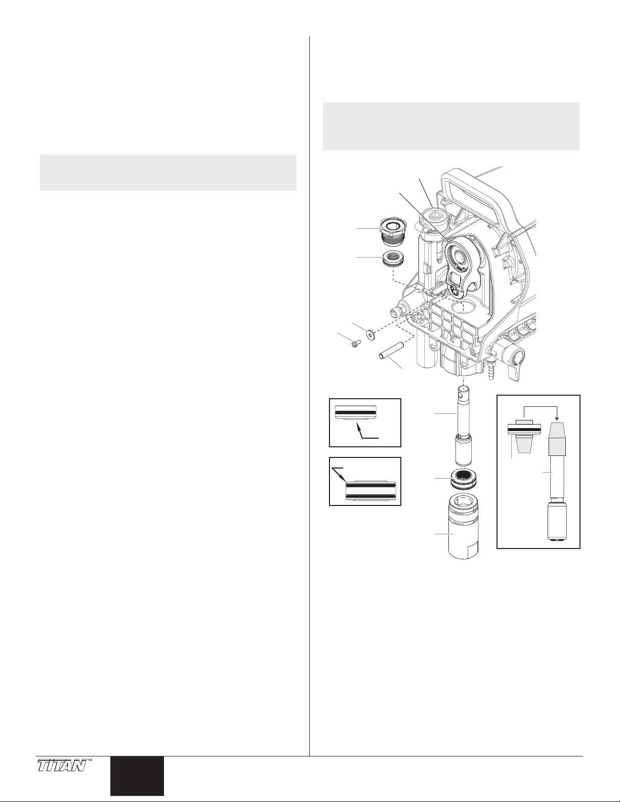
Repacking the Fluid Section
14
25
Disassembly
1. Rotate the pump shaft so the piston is in the top dead center
position. This can be done by moving the yoke.
2. Remove the yoke screw (14) and washer (15) that secures the
dowel pin (16). The dowel pin connects the yoke (17) to the
piston (18).
3. Using a pliers, pull the dowel pin (16) out.
4 Remove the piston assembly (18) by pushing down on the
piston near the yoke (17).
12. Reinstall the inlet valve assembly (22). Tighten by hand until
it cannot be tightented further, and then tighten another 1/2
turn with a wrench. This will automatically secure the lower
packing (21) into place.
13. Install front cover and three screws.
14. Reinstall the pressure control knob. Secure with the screw.
NOTE: If the knob bottom (25) has been removed from the
pressure switch assembly, it must be re-calibrated
prior to reinstallation. Follow the “Resetting the
Pressure Switch Timing” instructions.
NOTE: Inspect the piston rod for wear and replace if
5. Unscrew and remove the upper bushing (19) using an
6. Remove the worn seals using a at head screwdriver or punch.
7. Clean the area where the new packings are to be installed.
Reassembly
1. Slide the upper packing (20) o the grey sizing/insertion tool
2. Place the upper bushing (19) into the top of the housing and
3. Tilt the pump backwards so that it is laying on its back.
IMPORTANT: Cut the plastic wrap with a scissors. Do not cut
plastic wrap with a utility knife as damage can occur to the
O-rings.
4. Slide the lower packing (21) o the pre-form tool (towards the
5. Thread the inlet valve housing (22) back into the bottom
6. Place the grey insertion tool over the top of the piston
7. Insert the piston assembly into the bottom of the pump block
IMPORTANT: Make sure the piston is inserted precisely through
the middle of the upper and lower packing. Coming in at an
angle will bump the piston into the sides of the packings and
cause damage.
8. Apply any type of household grease to the piston and yoke
9. Install the dowel pin (16) to connect the yoke (17) to the
10. Install the yoke screw (14) and washer (15) to secure the dowel
11. Turn pump right side up and apply a few drops of Separating
necessary. Use piston assembly kit P/N 0532204A.
adjustable wrench.
Remove the upper packing (20) from the top and the lower
packing (21) from the bottom by pressing against the side
of the seal and popping it out. Be sure not to scratch the
housing where the seals are located.
(towards the tip) and install into the top of the pump housing
with the raised lip (23) facing down. Save the upper packing
sizing/insertion tool for use in step 6.
tighten with an adjustable wrench (torque to 300-360 in-lbs).
This will drive the upper packing (20) into the correct position.
Remove the plastic wrap from the lower packing and red preform tool.
top). Insert the lower packing partially into the bottom of the
pump block so that the beveled edge (24) of the packing faces
up.
of the pump housing by hand to drive the lower packing
into place. Once tightened as far as it will go, unthread and
remove again.
assembly (18). Coat the piston guide tool and the piston rod
with grease before inserting them into the pump housing.
and push upward until the hole in the piston is aligned with
the hole in the yoke (17). Discard insertion tool
area to prolong life. Apply to the holes in the yoke where the
dowel (16) is inserted.
piston (18). The piston may have to be moved up or down to
do this.
pin.
Oil or light household oil between the upper bushing (19) and
piston (18). This will prolong the seal life.
17
19
20
15
16
18
23
24
21
20
18
22
14 © Titan Tool Inc. All rights reserved.
English English
Page 15

Troubleshooting
Problem
A. The unit will not run.
B. The unit will not prime.
C. The unit will not build or
maintain pressure.
D. Fluid leakage at the upper end
of the uid section.
E. Excessive surge at the spray
gun.
Cause
1. The unit is not plugged in.
2. Tripped breaker.
3. The pressure is set too low (pressure control
knob set at minimum setting does not supply
power to unit).
4. Faulty or loose wiring.
5. Excessive motor temperature.
6. ON/OFF switch is defective.
1. The PRIME/SPRAY valve is in the SPRAY
position.
2. Air leak in the siphon tube/suction set.
3. The pump lter and/or inlet screen is clogged.
4. The siphon tube/suction set is clogged.
1. The spray tip is worn.
2. The spray tip is too large.
3. The pressure control knob is not set properly.
4. The pump lter, gun lter, or inlet screen is
clogged.
5. Material ows from the return hose when the
PRIME/SPRAY valve is in the SPRAY position.
6. Air leak in the siphon tube/suction set.
7. There is external uid leak.
8. There is an internal uid section leak
(packings are worn and/or dirty, valve balls
are worn).
9. Worn valve seats
10. Motor powers but fails to rotate
1. The upper packing is worn.
2. The piston rod is worn.
1. Wrong type of airless spray hose.
2. The spray tip worn or too large.
3. Excessive pressure.
Solution
1. Plug the unit in.
2. Reset the breaker.
3. Turn the pressure control knob clockwise to supply
power to the unit and increase the pressure setting.
4. Inspect or take to a Titan authorized service center.
5. Allow motor to cool.
6. Replace the ON/OFF switch.
1. Rotate the PRIME/SPRAY valve clockwise to the PRIME
position.
2. Check the siphon tube/suction set connection and
tighten or re-tape the connection with PTFE tape.
3. Remove the pump lter element and clean. Remove the
inlet screen and clean.
4. Remove the siphon tube/suction set and clean.
1. Replace the spray tip following the instructions that
came with the spray gun.
2. Replace the spray tip with a tip that has a smaller orice
following the instructions that came with the spray gun.
3. Turn the pressure control knob clockwise to increase the
pressure setting.
4. Remove the pump lter element and clean. Remove the
gun lter and clean. Remove the inlet screen and clean.
5. Clean or replace the PRIME/SPRAY valve.
6. Check the siphon tube/suction set connection and
tighten or re-tape the connection with PTFE tape.
7. Check for external leaks at all connections. Tighten
connections, if necessary.
8. Clean the valves and service the uid section following
the “Servicing the Fluid Section” procedure in the
Maintenance section of this manual.
9. Replace the valve seats following the “Servicing the Fluid
Section” procedure in the Maintenance section of this
manual.
10. Take unit to a Titan authorized service center.
1. Repack the pump following the “Servicing the Fluid
Section” procedure in the Maintenance section of this
manual.
2. Replace the piston rod following the “Servicing the Fluid
Section” procedure in the Maintenance section of this
manual.
1. Replace hose with a minimum of 50’ of 1/4” grounded
textile braid airless paint spray hose.
2. Replace the spray tip following the instructions that
came with the spray gun.
3. Rotate the pressure control knob counterclockwise to
decrease spray pressure.
F. Poor spray pattern.
G. The unit lacks power.
H. Pump over-pressurizes and will
not shut o.
© Titan Tool Inc. All rights reserved. 15
1. The spray tip is too large for the material
being used.
2. Incorrect pressure setting.
3. Insucient uid delivery.
4. The material being sprayed is too viscous.
1. The pressure adjustment is too low.
2. Improper voltage supply.
1. Pressure switch defective.
2. Transducer defective.
1. Replace the spray tip with a new or smaller spray tip
following the instructions that came with the spray gun.
2. Rotate the pressure control knob to adjust the pressure
for a proper spray pattern.
3. Clean all screens and lters.
4. Add solvent to the material according to the
manufacturer’s recommendations.
1. Rotate the pressure control knob clockwise to increase
the pressure setting.
2. Reconnect the input voltage for 120V AC.
1. Take unit to a Titan authorized service center.
2. Take unit to a Titan authorized service center.
Page 16
Consignes de sécurite important
Lire toutes ces consignes avant d’utiliser l’appareil.
Garder ces consignes.
Indique une situation à risque, laquelle, si elle n’est pas
évitée, peut entraîner des blessures graves, voire la mort.
Pour réduire les risques d’incendie ou d’explosion,
de choc électrique et de blessure, vous devez lire et
comprendre les directives gurant dans ce manuel.
Familiarisez-vous avec les commandes et l’utilisation
adéquate de l’équipement.
Directives de mise à la terre
Cet appareil doit être mis à la terre. En cas de court-circuit, cette précaution
réduit les risques de choc en procurant un parcours au courant électrique. Le
cordon de l’appareil est doté d’un l de terre relié à la troisième broche de sa
che. Cette dernière doit être branchée dans une prise correctement câblée et
mise à la terre conformément aux codes et règlements locaux.
MISE EN GARDE - Le fait de ne pas brancher correctement la
che trilaire de l’appareil peut entraîner des risques de choc
électrique.
Si on doit réparer ou remplacer le cordon ou la che, ne pas raccorder le
l de terre à la borne des broches plates (lames) de cette dernière. Ce l,
normalement vert (avec ou sans rayures jaunes), doit être relié à la broche de
terre.
Consulter un technicien ou un électricien qualié à défaut de comprendre
l’ensemble des présentes directives ou en cas d’incertitude quant à la mise à
terre de l’appareil. Ne pas modier la che de l’appareil; si elle ne s’adapte pas
dans la prise voulue, la faire remplacer par un électricien qualié.
Conçu pour les circuits de 120 V, cet appareil est doté d’une che ressemblant
à celle illustrée ci-dessous. S’assurer que le produit est connecté à une prise
électrique ayant la même conguration que la che mâle. Ne pas utiliser
d’adaptateur avec ce produit.
Prise trilaire
Broche de mise à la terre
Plaque murale de la prise
IMPORTANT: Quand le pulvérisateur est utilisé avec un générateur de
tension de la ligne ou non, l’utilisation de Titan “Line Surge Protector” (P
/ N 800-935) est recommandé.
MISE EN GARDE : EXPLOSION OU INCENDIE
Les émanations de certains produits peuvent exploser
ou s’enammer, et risquent d’entraîner des dommages
matériels ou de graves blessures.
MESURES PRÉVENTIVES :
• Ne pulvérisez pas de matières inammables ou combustibles près
d’une amme nue, de voyants lumineux ou de sources d’ignition
telles que des objets chauds, cigarettes, moteurs, matériel et appareils
électriques. Évitez de produire des étincelles en connectant et en
déconnectant les cordons électriques.
• S’entourer de toutes les précautions possibles lorsqu’on utilise
des produits ayant un point d’éclair inférieur à 38°C (100°F). Le
point d’éclair est la température à laquelle le liquide peut créer
susamment de vapeurs et s’enammer.
• L’écoulement de peinture ou de solvant dans l’équipement peut
produire de l’électricité statique. L’électricité statique crée un risque
d’incendie ou d’explosion en présence de fumées de peinture ou de
solvant. Toutes les pièces du système du pulvérisateur, y compris la
pompe, l’ensemble du tuyau, le pistolet de pulvérisation et les objets
dans et autour de la zone de pulvérisation doivent être correctement
reliés à la terre pour protéger contre les décharges d’électricité
statique et les étincelles. N’utilisez que des tuyaux conducteurs ou
reliés à la terre pour pulvérisateurs de peinture sous vide à haute
pression, spéciés par le fabricant.
• Vériez que tous les conteneurs ou systèmes de stockage sont reliés à
la terre pour éviter les décharges d’électricité statique.
• Connectez à une prise électrique avec prise de terre et utilisez des
rallonges électriques reliées à la terre. N’utilisez pas d’adaptateur 3 à 2.
• N’utilisez pas de peinture ou de solvant contenant du halon,
par exemple, le chlore, les agents antimoisissure à l’eau de
Javel, le chlorure de méthylène et le trichloroéthane. Ils ne sont
pas compatibles avec l’aluminium. Contactez le fournisseur de
revêtements pour connaître la compatibilité du matériau avec
l’aluminium.
• La zone de pulvérisation doit toujours être bien aérée. Une
bonne quantité d’air frais doit constamment traverser la zone de
pulvérisation pour éviter les accumulations de vapeurs inammables.
Le système de pompage doit être placé dans une zone bien aérée. Ne
pulvérisez pas le système de pompage.
• Ne fumez pas dans la zone de pulvérisation.
• N’actionnez pas d’interrupteurs électriques, de moteurs ou autres
dispositifs produisant des étincelles dans la zone de pulvérisation.
• Maintenez la propreté de la zone et veillez à ce qu’elle ne contienne
pas de conteneurs de peinture ou de solvant, de chions et autres
matières inammables.
• Sachez ce que contiennent la peinture et les solvants pulvérisés. Lisez
les ches de sécurité du matériel (MSDS) et les étiquettes apposées sur
les conteneurs de peintures et de solvants. Respectez les consignes de
sécurité du fabricant de peinture et de solvant.
• Placez la pompe à une distance minimum de 7,62 mètres (25 pieds) de
l’objet à pulvériser, dans une zone bien aérée (ajoutez de la longueur
de tuyau si besoin est). Les vapeurs inammables sont souvent plus
lourdes que l’air. La zone près du sol doit être très bien aérée. La
pompe contient des pièces qui produisent des arcs et émettent des
étincelles pouvant enammer les vapeurs.
• Le plastique peut causer des étincelles d’électricité statique.
N’accrochez aucun plastique dans une zone de pulvérisation fermée.
N’utilisez pas de toiles de protection en plastique quand vous
pulvérisez une matière inammable.
• Ayez un extincteur en bon état de fonctionnement à portée de main.
MISE EN GARDE : INJECTION CUTANÉE
Le jet de haute pression produit par cet appareil peut
transpercer la peau et les tissus sous-jacents, causant des
blessures graves pouvant entraîner l’amputation.
MESURES PRÉVENTIVES :
• Ne dirigez pas le pistolet sur et ne pulvérisez pas les personnes ou les
animaux.
• N’approchez pas les mains ni d’autres parties du corps de la sortie du
produit. Par exemple, ne tentez pas d’arrêter une fuite avec une partie
du corps.
• NE JAMAIS mettre la main, même gantée, devant le pistolet (les gants
n’orent aucune protection contre les blessures par injection).
• TOUJOURS s’assurer que le protège-embout est en place avant
de pulvériser. Il est cependant à noter que, s’il assure une certaine
protection, ce dispositif joue surtout un rôle préventif.
• Utilisez exclusivement un embout de buse spécié par le fabricant.
• Prenez garde quand vous nettoyez ou que vous changez les embouts
de buse. Si l’embout se bouche pendant que vous pulvérisez,
verrouillez TOUJOURS la détente du pistolet, arrêtez la pompe et
libérez toute la pression avant de réparer ou de nettoyer l’embout
ou le protecteur ou avant de changer d’embout. La pression n’est
pas libérée par l’arrêt du moteur. La poignée du robinet-valve PRIME/
SPRAY doit être placée sur PRIME pour libérer la pression. Consultez
la PROCÉDURE DE DÉCOMPRESSION décrite dans le manuel de la
pompe.
• Ne laissez pas l’appareil sous tension ou sous pression quand vous
vous en éloignez. Quand vous n’utilisez pas l’appareil, éteignez-le et
libérez la pression conformément aux instructions du fabricant.
• La pulvérisation à haute pression peut injecter des toxines dans le
corps et causer de graves blessures corporelles. Si une telle injection se
produisait, consultez immédiatement un médecin.
• Vériez les tuyaux et les pièces pour détecter des signes
d’endommagement : une fuite peut injecter le produit dans la peau.
Inspectez le tuyau avant chaque emploi. Changez tous les tuyaux ou
pièces endommagés. Pour des raisons de fonctionnement, de sécurité
16 © Titan Tool Inc. Tous droits réservés.
Français
Page 17
Consignes de sécurite important
et de durée de vie, utiliser exclusivement des tuyaux exibles à haute
pression d‘origine de TITAN.
• Ce système peut produire une pression de 3 000 PSI / 207 Bar.
N’utilisez que les pièces de rechange ou les accessoires spéciés par le
fabricant et ayant une pression nominale minimum de 3 300 PSI. Ceci
est valable pour les embouts de pulvérisation, les protecteurs de buse,
les pistolets, les rallonges, les raccords et le tuyau.
• Verrouillez toujours la détente quand vous ne pulvérisez pas. Vériez
que le verrou de la détente fonctionne correctement.
• Vériez que toutes les connexions sont bien serrées avant d’utiliser
l’appareil.
• Sachez comment arrêter l’appareil et le dépressuriser rapidement.
Soyez bien familiarisé avec les commandes. La pression n’est pas
libérée lorsque le moteur est arrêté. La poignée du robinet-valve
PRIME/SPRAY doit être placée sur PRIME pour libérer la pression.
Consultez la PROCÉDURE DE DÉCOMPRESSION décrite dans le
manuel de la pompe.
• Retirez toujours l’embout de pulvérisation avant de rincer ou de
nettoyer le système.
REMARQUE À L’INTENTION DES MÉDECINS : Les injections cutanées
sont des lésions traumatiques; il importe donc de les traiter sans délai.
On NE DOIT PAS retarder ce traitement sous prétexte de vérier la
toxicité du produit en cause, celle-ci n’étant conséquente que dans le
cas d’injection directe de certains produits dans le système sanguin.
Il pourrait s’avérer nécessaire de consulter un plasticien ou un
spécialiste en chirurgie reconstructive de la main.
MISE EN GARDE : ÉMANATIONS DANGEREUSES
Certains produits (peintures, solvants, insecticides ou
autres) peuvent être nocifs s’ils sont inhalés ou entrent en
contact avec l’organisme. Les émanations de ces produits
peuvent provoquer de graves nausées, évanouissements
ou empoisonnements.
MESURES PRÉVENTIVES :
• Se servir d’un masque ou d’un respirateur s’il y a risque d’inhalation
(lire toutes les directives concernant ces dispositifs an de s’assurer
qu’ils orent la protection requise).
• Porter des lunettes de protection.
• Porter les vêtements de protection prescrits par le fabricant du
produit utilisé.
MISE EN GARDE : GÉNÉRALITÉS
D’autres dangers peuvent entraîner des dommages
matériels ou des blessures graves.
MESURES PRÉVENTIVES :
• Portez toujours les gants, la protection oculaire, les vêtements et un
respirateur ou masque appropriés quand vous peignez.
• Ne travaillez pas et ne pulvérisez pas près d’enfants. Éloignez toujours
les enfants de l’équipement.
• Ne travaillez pas avec les bras au-dessus de la tête ni sur un support
instable. Appuyez-vous bien sur les deux pieds pour toujours
conserver l’équilibre.
• Soyez attentif et regardez ce que vous faites.
• N’utilisez pas l’appareil quand vous êtes fatigué ou sous l’inuence de
drogues ou d’alcool.
• Ne faites pas de nœuds avec le tuyau et ne le tordez pas trop. Le
tuyau à vide peut présenter des fuites suite à l’usure, les nœuds ou
les mauvais traitements. Une fuite risque d’injecter du produit dans la
peau.
• N’exposez pas le tuyau à des températures ou des pressions
supérieures à celles spéciées par le fabricant.
• N’utilisez pas le tuyau pour tirer ou soulever l’équipement.
• Utilisez la plus basse pression possible pour rincer l’équipement.
• Respectez tous les codes locaux, étatiques et nationaux qui régulent
la ventilation, la prévention d’incendies et le fonctionnement.
• Les normes de sécurité du gouvernement des États-Unis ont été
adoptées dans la loi Occupational safety and Health Act (OSHA). Ces
normes, en particulier la partie 1910 des Normes générales et la partie
1926 des Normes de construction, doivent être consultées.
• Avant chaque emploi, vériez tous les tuyaux pour détecter
d’éventuelles coupures, fuites, abrasion ou couvercle bombé. Vériez
l’état ou le mouvement des accouplements. Changez immédiatement
le tuyau si l’une de ces conditions est vériée. Ne réparez jamais un
tuyau de peinture. Remplacez-le par un tuyau conducteur à haute
pression.
• Ne pulvérisez pas à l’extérieur par temps venteux.
• Débranchez toujours le cordon électrique de la prise avant de
travailler sur l’équipement.
Spécications
Débit (LPM) 1,8 LPM
Embout, dimension max. 0,021” (0,53 mm)
Pression max. 3 000 PSI (20,7 MPa)
Source de puissance 0,75 HP DC moteur, 120V, 60 Hz
Poids 12,2 kg
Flexible, dimension max. 30,5 m (100’)
Génératrice 5 000 watts, 20 A, générateur
sinusoïdal, fonctionnalité de régime
ralenti désactivée
Table des matières
Consignes de sécurité ................................................................... 16
Specications ................................................................................. 17
Description générale ..................................................................... 18
Fonctionnement ............................................................................ 18
Verrouillage du pistolet de pulvérisation ..........................................18
Procédure de décompression ................................................................18
Vérications préliminaires .......................................................................19
Préparation d’un nouveau vaporisateur ............................................19
Préparation avant de peindre ................................................................19
Peinture ..........................................................................................................19
Vaporisation .................................................................................. 20
Technique de vaporisation .....................................................................20
Essais préliminaires ....................................................................................21
Dégager la buse de pulvérisation .........................................................21
Nettoyage ...................................................................................... 22
Maintenance .................................................................................. 23
Généralités concernant la maintenance ............................................23
Remplacement du moteur ......................................................................23
Remplacement des engrenages ...........................................................24
Remplacement du pressostat / transducteur ...................................24
Remplacer la carte de circuit imprimé ................................................25
Remplacement de la soupape PRIME/SPRAY ..................................26
Remplacement des ltres ........................................................................26
Maintenance de la section des liquides .............................................27
Dépannage ..................................................................................... 29
Listes de pièces .............................................................................. 44
Vue d’ensemble ...........................................................................................44
Ensemble de support ................................................................................45
Boîte d’engrenages I ..................................................................................46
Boîte d’engrenages II.................................................................................48
Ensemble d’aspiration ..............................................................................50
Étiquettes ......................................................................................................51
Schéma de raccordement électrique ........................................... 52
Enregistrement du produit ........................................................... 53
Accessoires ................................................................................54/55
Garantie .......................................................................................... 56
© Titan Tool Inc. Tous droits réservés. 17
Français
Page 18

Description générale
1
11
12
Ce vaporisateur à dépression est un outil électrique de précision
servant à atomiser divers types de matériaux. On doit lire et suivre
attentivement les directives apparaissant dans ce manuel pour
savoir comment l’utiliser et le maintenir en bon ordre, et ce, en toute
sécurité.
6
2
7
3
4
5
8
Fonctionnement
Cet appareil produit un jet à très haute pression; avant
de le faire fonctionner, il est donc essentiel de lire et de
comprendre les avertissements formulés dans la section
Consignes de sécurité à l’avant de ce manuel.
IMPORTANT: Les évents au bas et à l’arrière du capot du moteur
sont conçus pour empêcher le moteur de devenir excessivement
chaud pendant son utilisation. Assurez-vous que les évents au
bas et à l’arrière du capot du moteur ne sont pas recouverts ou
obstrués.
Verrouillage du pistolet de pulvérisation
1. Pour verrouiller le pistolet, tournez le verrou de détente vers
l’avant et légèrement vers le bas jusqu’à la butée.
2. Pour déverrouiller le pistolet, tourner le verrou de détente de
manière qu’il soit vertical et pointe vers le haut.
9*
k
PRIME
Art. Description
1 Moteur
2 Bouton de régulation de pression
3 Coupelle d’huile
4 Raccord de exible
5 Filtre
6 Flexible d’aspiration
7 Tube de retour
8 Communtateur ON/OFF
9 Soupape PRIME/SPRAY
10 Cuvette d’égouttage
11 Liquid Shield™ (118 ml)
12 Piston Lube™ (118 ml)
9*
10
SPRAY
p
Pistolet verrouillé
(le pistolet ne peut
pas pulvériser)
Pistolet déverrouillé
(le pistolet peut
pulvériser)
Procédure de décompression
On doit effectuer la procédure de décompression chaque
fois qu’on arrête l’appareil pour en faire la maintenance,
en changer les réglages de vaporisation, en remplacer/
nettoyer les embouts ou en effectuer la préparation en
vue d’un nettoyage.
1. Verrouiller le pistolet en mettant le verrou de détente à la
position appropriée.
2. Abaisser la soupape PRIME/SPRAY à la position PRIME.
3. Arrêter l’appareil en mettant le commutateur à la position
OFF.
4. Tourner le bouton de régulation de la pression à fond dans le
sens inverse des aiguilles d’une montre jusqu’au minimum.
5. Déverrouiller le pistolet en mettant le verrou de détente à la
position appropriée.
6. Tenir fermement la partie métallique du pistolet contre le bord
d’un contenant métallique an d’éviter une accumulation
d’électricité statique.
7. Appuyer sur la détente du pistolet an de purger tout l’air
restant dans le exible.
8. Verrouiller le pistolet en mettant le verrou de détente à la
position appropriée.
18 © Titan Tool Inc. Tous droits réservés.
Français
Page 19

Vérications préliminaires
On doit procéder aux étapes suivantes avant de brancher le cordon
d’alimentation de l’appareil.
1. S’assurer que le exible et le bloc d’aspiration soient
solidement xés.
2. Fixer un exible de vaporisation à tresse de Nylon, conçu pour
les appareils à dépression, et mesurant au moins 15 mètres (50
pi).
3. Fixer un pistolet à dépression au exible de vaporisation; ne
pas xer l’embout au pistolet tout de suite (le retirer s’il est
déjà xé).
NOTA : Ne pas encore xer l’embout sur le pistolet de
vaporisation. Démonter l’embout s’il est déjà xé.
Assurez-vous que tous les tuyaux et pistoletspulvérisateurs sans air comprimé sont mis à la terre
et que leur pression de régime nominale atteint ou
dépasse la plage maximale du pulvérisateur sans air
comprimé.
4. Tourner à fond le bouton de régulation de la pression dans le
sens inverse des aiguilles d’une montre jusqu’au minimum de
pression.
5. S’assurer que le commutateur soit à la position OFF.
6. Remplir la coupelle à l’huile de la section de liquide avec
environ une cuillerée à Piston Lube™ (voir la section
“Accessiores”, page 54).
IMPORTANT : Ne jamais faire fonctionner l’appareil sans liquide
pendant plus de 10 secondes, ce qui pourrait user inutilement les
tampons graisseurs.
7. S’assurer que l’alimentation électrique soit d’au moins 15 A à
120 V.
8. Brancher le cordon d’alimentation dans une prise
adéquatement mise à la terre située à une distance d’au moins
7,5 m (25 pi) de la surface à vaporiser.
IMPORTANT : Les rallonges utilisées doivent être trifilaires, de
calibre 12 et dotées d’une fiche à broche de MALT; on ne doit
jamais retirer cette troisième broche ou utiliser un adaptateur.
Préparation d’un nouveau vaporisateur
Si cet appareil est neuf, il contient encore un liquide d’essai mis en
usine pour le protéger de la corrosion en cours d’expédition ou
d’entreposage. Ce liquide doit être complètement éliminé au moyen
d’essence minérale avant que l’appareil puisse être utilisé.
IMPORTANT : La détente du pistolet doit toujours être
verrouillée lorsqu’on procède à ces vérifications préliminaires.
1. Mettre le exible d’aspiration dans un contenant d’essence
minérale.
2. Mettre le exible de retour dans un contenant de purge
métallique.
3. Tourner le bouton de régulation de la pression à fond dans le
sens inverse des aiguilles d’une montre jusqu’au minimum.
4. Abaisser la soupape PRIME/SPRAY à la position PRIME.
5. Mettre l’appareil en marche en mettant le commutateur à la
position ON.
6. Laisser le vaporisateur fonctionner pendant 15 à 30 secondes
pour évacuer le liquide d’essai par le exible de retour,
jusqu’au contenant de purge.
7. Arrêter l’appareil en mettant le commutateur à la position
OFF.
Préparation avant de peindre
Avant de peindre, il est important de s’assurer que le liquide dans
l’appareil est compatible avec le produit à utiliser.
NOTA : L’incompatibilité liquide/produit peut provoquer le
blocage des soupapes, ce qui entraînerait le besoin
de démonter et de nettoyer la section des liquides du
vaporisateur.
IMPORTANT : La détente du pistolet doit toujours être
verrouillée lorsqu’on procède à ces vérifications préliminaires.
1. Mettre le exible d’aspiration dans un contenant de solvant
approprié (de l’eau dans le cas de peintures au latex, de
l’essence minérale dans le cas de peintures à l’huile, etc.).
2. Mettre le exible de retour dans un contenant de purge
métallique.
3. Tourner le bouton de régulation de la pression à fond dans le
sens inverse des aiguilles d’une montre jusqu’au minimum.
4. Abaisser la soupape PRIME/SPRAY à la position PRIME.
NOTA : Tenez le tube de retour dans le conteneur de déchets
en faisant passer le PRIME / SPRAY soupape de PRIME
dans le cas où le pulvérisateur est sous pression.
5. Mettre l’appareil en marche en mettant le commutateur à la
position ON.
6. Laisser le vaporisateur fonctionner pendant 15 à 30 secondes
pour évacuer le solvant usé par le exible de retour, jusqu’au
contenant de purge.
7. Arrêter l’appareil en mettant le commutateur à la position
OFF.
NOTA : S’assurer que l’embout ou le protège-embout ne
soient pas installés.
8. Soulever la soupape PRIME/SPRAY à la position SPRAY.
9. Mettre l’appareil en marche.
10. Déverrouiller le pistolet en mettant le verrou de détente à la
position appropriée.
On doit mettre le pistolet à la terre en le tenant contre
le bord du contenant de purge métallique pendant
qu’il se vide afin d’éviter les risques de décharges
électrostatiques, lesquelles peuvent provoquer un
incendie.
11. Appuyer sur la détente en visant le contenant métallique pour
purger le solvant usé du pistolet, jusqu’à ce que du solvant
frais en ressorte.
12. Verrouiller le pistolet en mettant le verrou de détente à la
position appropriée.
13. Déposer le pistolet et augmenter la pression en tournant
lentement le bouton de régulation vers la droite.
14. Inspecter tous les composants an d’y détecter des fuites
potentielles. Le cas échéant, suivre les directives de la section
“Procédure de décompression” du présent manuel avant de
xer les exibles et de serrer les raccords.
15. Procéder aux étapes de la section “Procédure de
décompression” du présent manuel avant de passer du
solvant au produit de peinture.
© Titan Tool Inc. Tous droits réservés. 19
On doit eectuer la “Procédure de décompression”
chaque fois qu’on arrête l’appareil pour en faire la
maintenance, en changer les réglages de vaporisation,
en remplacer/ nettoyer les embouts ou en eectuer la
préparation en vue d’un nettoyage.
Français
English
Page 20

Peinture
régulier et à vitesse constante.
Revêtement également réparti
Revêtement épais
Ne pas échir le poignet durant la pulvérisation
Revêtement n Revêtement n
Environ
1. Mettre le exible d’aspiration dans un contenant de produit
de peinture.
2. Mettre le exible de retour dans un contenant de purge
métallique.
3. Tourner le bouton de régulation de la pression à fond dans le
sens inverse des aiguilles d’une montre jusqu’au minimum.
4. Abaisser la soupape PRIME/SPRAY à la position PRIME.
5. Mettre l’appareil en marche en mettant le commutateur à la
position ON.
6. Laisser le vaporisateur fonctionner jusqu’à ce que le produit
commence à s’écouler par le exible de retour dans le
contenant de purge.
7. Arrêter l’appareil en mettant le commutateur à la position
OFF.
8. Retirer le exible de retour du contenant de purge et le mettre
à sa position normale, au-dessus du contenant de produit de
peinture.
9. Soulever la soupape PRIME/SPRAY à la position SPRAY.
10. Mettre l’appareil en marche.
11. Déverrouiller le pistolet en mettant le verrou de détente à la
position appropriée.
On doit mettre le pistolet à la terre en le tenant contre
le bord du contenant de purge métallique pendant
qu’il se vide afin d’éviter les risques de décharges
électrostatiques, lesquelles peuvent provoquer un
incendie.
Vaporisation
RISQUES D’INJECTION. Ne pas vaporiser sans avoir
installé le protège-embout. Ne jamais appuyer
sur la détente sans avoir mis l’embout en position
de vaporisation ou de désobstruction. Toujours
enclencher le verrou de détente avant de retirer, de
remplacer ou de nettoyer l’embout.
Technique de vaporisation
Pour obtenir une peinture d’un ni impeccable il est essentiel que le
produit soit également réparti sur toute la surface. Il faut pour cela que
vous appliquiez la peinture de façon régulière en déplaçant votre bras
à vitesse constante et en gardant le pistolet de pulvérisation à une
distante constante de la surface. La meilleure distance de pulvérisation
est de 25 à 30 cm entre le pistolet et la surface traitée.
Environ 25 à 30 cm
Déplacez votre bras d'un mouvement
12. Appuyer sur la détente en visant le contenant métallique pour
purger le solvant et l’air du exible de vaporisation, jusqu’à ce
que le produit de peinture s’écoule librement du pistolet.
13. Verrouiller le pistolet en mettant le verrou de détente à la
position appropriée.
14. Arrêter l’appareil.
15. Fixer l’embout et le protège-embout au pistolet,
conformément aux directives accompagnant ces derniers.
RISQUES D’INJECTION. Ne pas vaporiser sans avoir
installé le protège-embout. Ne jamais appuyer
sur la détente sans avoir mis l’embout en position
de vaporisation ou de désobstruction. Toujours
enclencher le verrou de détente avant de retirer, de
remplacer ou de nettoyer l’embout.
16. Mettre l’appareil en marche.
17. Augmenter la pression en tournant lentement le bouton de
régulation vers la droite, jusqu’à la zone verte, puis eectuer
un essais sur un morceau de carton en examinant le jet
résultant. Régler la pression de manière à ce que le produit
soit parfaitement atomisé.
NOTA : Si la pression est trop élevée, l’embout subira une
usure prématurée et produira des éclaboussures de
surpulvérisation.
Gardez le pistolet perpendiculaire à la surface traitée. Il vous
faut pour cela déplacer tout votre bras de haut en bas et non pas
seulement échir votre poignet.
Veillez à garder le pistolet perpendiculaire à la surface traitée an
d’éviter qu’une extrémité de chaque passage soit plus épaisse que
l’autre.
25 à 30 cm
Bonne
technique
Mauvaise
technique
20 © Titan Tool Inc. Tous droits réservés.
Français
Page 21

Appuyez sur la gâchette au début et à la n de chaque passage. Vous
Comment bien utiliser la gâchette du pistolet
du passage
du passage
la gâchette
éviterez ainsi de gaspiller de la peinture ou d’avoir une accumulation
de peinture à l’extrémité du passage. Ne jouez pas avec la gâchette
durant le passage an d’éviter un ni irrégulier ou des éclaboussures.
Début
Déplacez votre bras
d'un mouvement
régulier
Appuyez sur
la gâchette
Environ 25 à 30 cm
(10 à 12 pi)
Gardez une
vitesse constante
Relâchez
Fin
Chevauchez chaque passage d’environ 50% an d’obtenir un ni
régulier.
Chevaucher d’environ 50%
Lorsqu’on arrête la peinture, il faut bloquer le cran de sûreté, tourner
le bouton de réglage de la pression dans le sens inverse des aiguilles
d’une montre jusqu’à ce qu’il atteigne sa valeur minimum, puis régler
le bouton d’amorçage à la position PRIME. Tourner le commutateur
du moteur à ARRÊT et débrancher le pulvérisateur.
Dégager la buse de pulvérisation
NOTA : Si la répartition de votre pulvérisation devient
déformée ou si la pulvérisation cesse complètement
au cours de la pulvérisation, suivez ces étapes.
Le débit passant par la buse de pulvérisation est à une
pression très élevée. Le contact avec une quelconque
partie du corps peut être dangereux. Ne placez pas un
doigt sur la sortie du pistolet. Ne pointez quiconque
avec le pistolet. N’utilisez jamais le pulvérisateur sans
le dispositif de protection de buse approprié.
1. Suivre la “Procédure de décompression” à la section
Fonctionnement du présent manuel.
2. Si la buse devient bouchée, tournez
la poignée de la buse de 180
degrés jusqu’à ce que la èche
sur la poignée soit orientée vers la
direction opposée à la pulvérisation
et la poignée s’enclenche dans la
position inverse.
3. Appuyez sur la détente du pistolet
une fois dans un contenant de
déchets de façon à ce que la pression puisse déboucher la
buse. N’utilisez JAMAIS la buse dans la position INVERSE plus
longtemps qu’UNE pression sur la détente du pistolet à la fois.
Cette procédure peut être répétée jusqu’à ce que la buse soit
débouchée.
Essais préliminaires
1. S’assurer que le exible à produit de peinture soit exempt de
coudes et éloigné de toute arête coupante.
2. Tourner le bouton de régulation de la pression à fond dans le
sens inverse des aiguilles d’une montre jusqu’au minimum.
3. Soulever la soupape PRIME/SPRAY à la position SPRAY.
4. Tourner le bouton de régulation de pression à son réglage le
plus élevé; le exible à produit devrait se raidir sous l’eet de
la pression.
5. Déverrouiller la détente du pistolet.
6. Appuyer sur la détente pour évacuer l’air du exible.
7. Quand la peinture atteint
l’embout, eectuer un essai de
vaporisation en vue de régler
le jet en fonction du travail à
eectuer.
8. Régler la pression au niveau le
plus bas qui permette d’obtenir
le jet désiré. Si elle est trop
basse, le jet produira des traînées
ou crachera des grumeaux de
produit.
NOTA : Si la pression est trop élevée, l’embout subira une
usure prématurée et produira des éclaboussures de
surpulvérisation.
Bonne répartition
de la pulvérisation
Traînées de peinture
© Titan Tool Inc. Tous droits réservés. 21
Français
English
Page 22

Nettoyage
Directives particulières pour le nettoyage au moyen de
solvants inflammables :
• Purger le pistolet à l’extérieur de préférence, à une distance
d’au moins une longueur de exible de la pompe.
• Si le solvant usé est recueilli dans un contenant métallique
de 4 litres (1 gallon), celui-ci doit être inséré dans un second
contenant d’au moins 20 litres (5 gallons).
• L’endroit choisi doit être exempt de vapeurs inammables.
• On doit suivre les directives de nettoyage à la lettre.
Lorsqu’on se sert d’essence minérale ou d’autres
solvants pour nettoyer le vaporisateur, le exible ou
le pistolet, on doit régler la pression au minimum et
retirer l’embout de la buse du pistolet. L’accumulation
d’électricité statique risque de provoquer des
incendies en présence de vapeurs inammables.
IMPORTANT : Le vaporisateur, le flexible et le pistolet doivent
être nettoyés en profondeur après chaque journée d’utilisation et
ce, afin d’éviter les accumulations de produit susceptibles de nuire
grandement au rendement de l’appareil.
1. Suivre la “rocédure de décompression” à la section
Fonctionnement du présent manuel.
2. Retirer l’embout et le protège-embout, et les nettoyer au
moyen d’une brosse et du solvant approprié.
3. Mettre le exible d’aspiration dans un contenant de solvant
approprié (de l’eau dans le cas de peintures au latex, de
l’essence minérale dans le cas de peintures à l’huile, etc.).
4. Mettre le exible de retour dans un contenant de purge
métallique.
5. Tourner le bouton de régulation de la pression à fond dans le
sens inverse des aiguilles d’une montre jusqu’au minimum.
6. Abaisser la soupape PRIME/SPRAY à la position PRIME.
15. Dégager et retirer le logement du ltre (1).
16. En tournant vers la droite, dévisser le ltre (2) du logement du
pompe (3).
NOTA : Le letage à gauche requiert qu’on tourne vers la
droite pour dévisser.
17. S’assurer que le joint de la ltre (4) soit bien placé.
18. En tournant vers la gauche, visser le ltre nettoyé ou de
rechange sur le logement du pompe.
19. Nettoyer l’intérieur du logement du ltre (1) à l’aide de la
solution de nettoyage appropriée.
20. Glisser le logement sur le ltre et le visser solidement sur le
bloc pompe.
3
1
4
2
21. Débrancher l’appareil et le ranger dans un endroit propre et
sec.
IMPORTANT : Ne pas ranger l’appareil sous pression.
NOTA : Tenez le tube de retour dans le conteneur de déchets
7. Mettre l’appareil en marche en mettant le commutateur à la
8. Laisser le solvant circuler dans l’appareil pour évacuer
9. Arrêter l’appareil en mettant le commutateur à la position OFF.
10. Soulever la soupape PRIME/SPRAY à la position SPRAY.
11. Mettre l’appareil en marche.
12. Appuyer sur la détente en visant le contenant métallique pour
13. Continuer d’appuyer sur la détente, en direction du contenant
NOTA : Pour l’entreposage à long terme en milieu froid,
Dans le cas de rangement à court terme après
14. Suivre la “Procédure de décompression” à la section
en faisant passer le PRIME / SPRAY soupape de PRIME
dans le cas où le pulvérisateur est sous pression.
position ON.
le produit de peinture par le exible de retour, jusqu’au
contenant de purge.
On doit mettre le pistolet à la terre en le tenant contre
le bord du contenant de purge métallique pendant
qu’il se vide afin d’éviter les risques de décharges
électrostatiques, lesquelles peuvent provoquer un
incendie.
purger le produit du exible, jusqu’à ce que le solvant s’écoule
du pistolet.
métallique, jusqu’à ce que le solvant évacué soit propre.
remplir tous les composants de l’appareil d’essence
minérale.
utilisation de peinture au latex, remplir tous les
composants d’eau mélangée au protecteur Titan Liquid
Shield (se reporter à la section Accessoires du présent
manuel pour obtenir le numéro de pièce de ce produit).
Fonctionnement du présent manuel.
22 © Titan Tool Inc. Tous droits réservés.
Français
Page 23

Maintenance
Remplacement du moteur
Avant de procéder, on doit suivre les directives de la
section “Procédure de décompression” du présent
manuel. On doit également respecter tous les autres
avertissements si on veut éviter les blessures par
injection, par contact avec une pièce mobile ou par choc
électrique. Le vaporisateur doit toujours être débranché
avant d’être entretenu ou réparé.
Généralités concernant la maintenance
Pour réparer ou entretenir le vaporisateur, on pourrait avoir à recourir
aux outils suivants :
Tournevis étoile Clé hexagonale de 1,0 cm (3/8 po)
Pince à bec pointu Clé hexagonale de 0,8 cm (5/16 po)
Clé à ouverture variable Clé hexagonale de 0,6 cm (1/4 po)
Maillet en caoutchouc Clé hexagonale de 0,5 cm (3/16 po)
Tournevis plat Clé hexagonale de 0,4 cm (5/32 po)
Clé dynamométrique (po-lb) Multimètre de résistance
Manomètre (P/N 0508239)
1. Avant de procéder à la maintenance de n’importe quel
composant du vaporisateur, il faut lire attentivement
les directives ainsi que tous les avertissements qu’elles
contiennent.
IMPORTANT : Ne jamais tirer sur le cordon pour le débrancher,
ce qui pourrait détacher le connecteur des fils.
2. Vérier les résultats de la maintenance eectuée avant
d’utiliser le vaporisateur en conditions normales an de
s’assurer que le problème ait bel et bien été corrigé. Si le
vaporisateur ne fonctionne toujours pas comme il faut,
repasser la procédure pour s’assurer qu’elle ait été bien suivie.
Se reporter ensuite à la section Dépannage pour cerner la
source potentielle du problème.
3. S’assurer que l’endroit choisi soit bien ventilé si des solvants
sont utilisés pour le nettoyage. Toujours porter des lunettes
de protection lorsqu’on procède à la maintenance. D’autres
dispositifs protecteurs pourraient être requis selon le type de
solvant utilisé; on doit toujours communiquer avec le fabricant
de ce dernier pour obtenir ses recommandations à cet eet.
4. Pour toute autre question relative à ce vaporisateur à
dépression, il sut de communiquer avec Titan :
Service à la clientèle ........................................... 1-800-526-5362
Télécopieur ................................................. 1-800-528-4826
NOTA : Il est recommandé que la procédure suivante soit
exécutée par un centre de service autorisé Titan.
1. Suivre la “Procédure de décompression” et débrancher
l’appareil.
2. Desserrer et retirer les quatre vis (1) du carter de moteur (2) et
retirer.
NOTA : L’interrupteur ON / OFF (3) est situé à l’intérieur du
carter du moteur. Pour retirer le carter de moteur
complètement, vous devez débrancher tous les ls
à l’arrière de l’interrupteur. Notez la position des ls
avant de les débrancher.
3. À l’arrière du moteur (4), débranchez les deux ls (noir et
rouge) provenant du circuit imprimé (5). Retirer le l de mise à
la terre du logement du moteur.
4. Glissez le déecteur du moteur (7) pour le retirer de l’arrière
du moteur.
5. Desserrer et retirer les quatre vis de montage du moteur (8).
6. Retirer le moteur (4) du logement de la pompe (9).
7. Une fois le moteur retiré, inspecter les engrenages dans
le logement de la pompe (9) pour y détecter d’éventuels
dommages ou une usure excessive. Les remplacer, le cas
échéant.
8. Installer le nouveau moteur (4) dans le logement de la pompe
(9).
9. Fixer le moteur au moyen des quatre vis de montage (8).
10. Reconnecter les ls (se reporter au schéma de raccordement
électrique de la section Listes de pièces du présent manuel).
11. Glissez le déecteur du moteur (7) sur l’arrière du moteur. Les
èches sur le déecteur devraient pointer vers le haut.
12. Glisser le carter sur le moteur (2) en le xant au moyen des
quatre vis prévues (1).
9
5
6
8
4
7
© Titan Tool Inc. Tous droits réservés. 23
Français
3
English
1
2
Page 24

Remplacement des engrenages
2
3
4
Remplacement du pressostat / transducteur
NOTA : Il est recommandé que la procédure suivante soit
1. Suivre la “Procédure de décompression” et débrancher
2. Desserrer et retirer les quatre vis du carter de moteur (1) et
NOTA : L’interrupteur ON / OFF (3) est situé à l’intérieur du
3. À l’arrière du moteur (4), débranchez les deux ls (noir et
4. Glissez le déecteur du moteur (7) pour le retirer de l’arrière
5. Desserrer et retirer les quatre vis de montage du moteur (8).
6. Retirer le moteur (4) du logement de la pompe (9).
7. Inspecter l’engrenage d’armature (10) à l’extrémité du
8. Retirer et inspecter le second engrenage (11) pour y détecter
9. Si l’engrenage d’armature (10) ou l’engrenage de 2e étage
10. Remonter la pompe en reprenant les étapes ci-dessus à
NOTA : Verser environ 150 ml (5 oz) de Lubriplate™ (no 314-
exécutée par un centre de service autorisé Titan.
l’appareil.
retirer ce premier (2).
carter du moteur. Pour retirer le carter de moteur
complètement, vous devez débrancher tous les ls
à l’arrière de l’interrupteur. Notez la position des ls
avant de les débrancher.
rouge) provenant du circuit imprimé (5). Retirer le l de mise à
la terre du logement du moteur.
du moteur.
moteur pour y détecter d’éventuels dommages ou une usure
excessive. Si cet engrenage est complètement usé, remplacer
tout le moteur.
d’éventuels dommages ou une usure excessive. Le remplacer,
le cas échéant.
(11) est endommagé, le boîtier de la pompe (9) doit être
nettoyé pour éliminer tous débris causés par des engrenages
endommagés.
l’envers.
171) dans la boîte d’engrenages.
9
5
11
10
6
8
4
7
NOTA : Il est recommandé que la procédure suivante soit
NOTA : Si le pulvérisateur perd tout ajustement de
1. Suivre la “Procédure de décompression” et débrancher
2. Retirez la vis (1) qui xe le bouton de commande de pression
3. Desserrer et retirer les quatre vis (1) du carter de moteur (2) et
4. Retirez la vis (7) du côté du pressostat. Retirez le bas du
5. Retirez l’assemblage du pressostat (6) du haut du transducteur (8).
6. Débrancher le
IMPORTANT : Ne pas tenter de tirer les ls de l’intérieur du
pressostat
pas exposé dans l’ouverture du logement de la pompe, tirer
doucement sur les ls jusqu’à ce que le capuchon de connexion
apparaisse.
7. Vérier la continuité du pressostat au niveau du capuchon de
8. Inspectez le transducteur (8) pour vérier s’il y a présence de
a. Au moyen d’une clé sur la tête hexagonale du transducteur,
b. Appliquez une quantité généreuse de graisse sur le joint torique du
9. Reconnecter les ls de pressostat (se reporter au schéma de
10. Poussez l’assemblage du pressostat (6) pour le remettre sur le
11. Replacez la vis (7) dans le côté du pressostat.
12. Voir la section “Réinitialiser la synchronisation du pressostat” à
1
2
exécutée par un centre de service autorisé Titan.
pression, ou s’il y a une fuite de l’avant du
pulvérisateur, le pressostat et/ou le transducteur
pourraient devoir être remplacés.
l’appareil.
(2) au bas du bouton de commande de pression (3). Retirez le
bouton (2).
retirer.
bouton de commande de pression (3) du haut du pressostat.
pressostat
. Si le capuchon de connexion (10) du
connexion. Si le manocontacteur est défectueux, le remplacer
par un nouveau manocontacteur.
peinture. S’il y a de la peinture, remplacez le transducteur. S’il
n’y a pas de peinture, passer à l’étape 9 ci-dessous.
desserrez et retirez l’assemblage du transducteur.
transducteur (9). Réinstallez l’assemblage du transducteur et serrez
au couple de 70 à 75 po-lb.
raccordement électrique de la section Listes de pièces du
présent manuel).
transducteur jusqu’à ce qu’il aboutisse sur la tête hexagonale
du transducteur.
la page suivante.
6
7
8
9
(6) du capuchon de connexion(10).
pressostat
10
n’est
3
1
5
24 © Titan Tool Inc. Tous droits réservés.
Français
Page 25

Réinitialiser la synchronisation du pressostat
8
NOTA : Il est recommandé que la procédure suivante soit
exécutée par un centre de service autorisé Titan.
11. Lorsque le manomètre lit entre 2 800 et 3 000 PSI, le bouton
de commande de pression est maintenant réglé. Fixez le
bouton de commande de pression avec la vis du bouton de
commande de pression.
NOTA : Les composants du pressostat doivent être
réassemblés de façon appropriée et ajustés an que
la pompe fonctionne à la bonne pression maximale.
Exécutez cette procédure au moyen du manomètre P/N 0508239.
1. Assurez-vous que le bas du bouton (1) est installé dans le
pressostat (2).
2. D’une vue du haut, tournez le bas du bouton (1) dans le
sans contraire aux aiguilles d’une montre aussi loin que le
permettront les dents à l’intérieur du pressostat.
1
3
2
NOTA : Si l’arrêt (3) sur le pressostat empêche le bas du
bouton de continuer de tourner, retirez le bas du
bouton, réorientez-le sur les dents et continuez de
le tourner dans le sens contraire aux aiguilles d’une
montre jusqu’à ce qu’il s’arrête.
3. Orienter à nouveau l’onglet du bouton contre la butée pour
onglet du manocontacteur.
Replacer le circuit imprimé
NOTA : Il est recommandé que la procédure suivante soit
exécutée par un centre de service autorisé Titan.
Exécutez cette procédure au moyen de la trousse de circuit imprimé
P/N 0532208A.
1. Suivre la “Procédure de décompression” et débrancher
l’appareil.
3. Desserrer et retirer les quatre vis (1) du carter de moteur (2) et
retirer.
3. Débranchez les ls rouge et noir qui relient le circuit imprimé
(3) à l’assemblage du moteur (4).
4. Débranchez les ls blancs qui relient le circuit imprimé au
pressostat.
NOTA : Le pressostat ne sera pas visible puisqu’il est situé
de l’autre côté du boîtier du moteur. Les ls blancs
seront visibles à travers une ouverture dans le
boîtier (5). Si le capuchon de connexion n’est pas
visible, tirer doucement sur les ls par l’ouverture
jusqu’à ce qu’il soit accessible.
5. Débranchez le l noir qui relie le circuit imprimé au disjoncteur
(6).
6. Débranchez le l blanc qui relie le circuit imprimé à
l’interrupteur d’alimentation (7).
7. Desserrez et retirez les deux vis du circuit imprimé (8). Retirez
le circuit imprimé (3).
8. Installez le nouveau circuit imprimé (3) et xez-le avec les
deux vis de circuit imprimé (8).
9. Rebranchez les ls qui ont été débranchés aux étapes 3 à 6 (se
reporter au schéma de raccordement électrique de la section
Liste de pièces du présent manuel).
10. Glisser le carter sur le moteur (2) en le xant au moyen des
quatre vis prévues (1).
4. Replacez le couvercle avant et xez-le au moyen des trois vis.
5. Replacez le bouton de commande de pression dans le bas
du bouton, mais ne le xez pas avec la vis. Tournez le bouton
entièrement dans le sens des aiguilles d’une montre.
6. Connectez le manomètre au raccord de sortie.
7. Connectez un tuyau et un pistolet à haute pression au
manomètre.
8. En utilisant l’eau comme milieu, suivez les étapes dans la
section “Peindre”. Il n’est pas nécessaire de xer une buse
de pulvérisation au pistolet. Laissez la pression réglée au
maximum.
9. Le pulvérisateur devrait maintenant être pressurisé à la
pression maximale. Le manomètre devrait lire une pression
d’entre 193 et 207 bar (2 800 et 3 000 PSI).
10. Si la pression est inférieure ou supérieure à cette valeur, la
vis de réglage à l’intérieur du pressostat devra être ajustée.
Ajustez la conformément aux lignes directrices ci-dessous au
moyen d’un long clé hexagonale.
a. Si la pression est inférieure à 193 bar (2 800 PSI), tournez la vis de
réglage dans le sens contraire aux aiguilles d’une montre jusqu’à ce
que le manomètre indique entre 193 et 207 bar (2 800 et 3 000 PSI).
b. Si la pression est supérieure à 207 bar (3 000 PSI), réduisez la
pression en tournant le bouton PRIME/SPRAY à PRIME. Pendant que
le pulvérisateur circule, tournez la vis de réglage dans le sens des
aiguilles d’une montre légèrement et ensuite tournez le bouton
PRIME/SPRAY à SPRAY. Répétez cela jusqu’à ce que la pression
baisse jusqu’à 2 800-3 000 PSI.
© Titan Tool Inc. Tous droits réservés. 25
5
4
1
2
7
6
3
Français
English
Page 26

Remplacement de la soupape PRIME/SPRAY
1
2
1
4
3
2
Pour eectuer cette procédure, on doit se procurer une trousse de
remplacement de soupape PRIME/SPRAY (Nº de pièce 700-258).
1. Pousser la goupille (1) hors de la manette de la soupape (2).
2. Retirer la manette (2) et la base à came (3).
3. Au moyen d’une clé, desserrer et retirer le logement de la
soupape (4).
4. S’assurer que le joint d’étanchéité (5) soit à sa place, et visser le
nouveau logement dans le bloc pompe (6); serrer fermement
à l’aide d’une clé.
5. Mettre la base à came (3) par dessus le logement de la
soupape (4); la lubrier au moyen de graisse et aligner la came
avec le bloc pompe (6).
6. Aligner le trou dans la tige de soupape (7) avec celui de la
manette (2).
7. Insérer la goupille à travers ces deux trous an de xer la
manette en place.
5
4
7
3
6
Remplacement des ltres
Filtre de pompe
1. Dégager et retirer le logement du ltre (1).
2. En tournant vers la droite, dévisser le ltre (2) du logement du
pompe (3).
NOTA : Le letage à gauche requiert qu’on tourne vers la
droite pour dévisser.
3. S’assurer que le joint de la ltre (4) soit bien placé.
4. En tournant vers la gauche, visser le ltre nettoyé ou de
rechange sur le logement du pompe.
5. Glisser le logement sur le ltre et le visser solidement sur le
bloc pompe.
3
1
4
2
NOTA : En présence de solvant CHAUDS, remplacer les
joints toriques en Viton (article 8) par ceux en PTFE
(700-897), installés au moyen de l’outil approprié
(700-890).
8
Filtre de pistolet
1. Déverrouiller la détente du pistolet.
2. Dégager et retirer la poignée (1) du corps du pistolet (2).
3. En tournant vers la droite, dévisser le ltre (3) du corps.
NOTA : Le letage à gauche requiert qu’on tourne vers la
4. En tournant vers la gauche, visser le ltre nettoyé ou de
5. S’assurer que le joint de la poignée soit bien placé et visser
6. Verrouiller la détente du pistolet.
droite pour dévisser.
rechange sur le corps.
solidement cette dernière sur le corps.
NOTA : Pour obtenir plus de détails, se renseigner sur les
26 © Titan Tool Inc. Tous droits réservés.
Français
numéros de pièce ou voir des dessins d’assemblage
à plus grande échelle, se reporter au manuel de
l’utilisateur du pistolet à dépression.
Page 27

Maintenance de la section des liquides
Trois trousses de réparation sont disponibles pour réparer la section
des liquides :
La trousse de garniture P/N 0532911 comprend :
Article Nº de
Écrou supérieur 0532215 Bille de soupape
Tampon graisseur
supérieur
Tampon graisseur
inférieur
Joint de soupape de
retenue
Joint torique, PTFE 762-058
pièce
0532914 Bille de soupape
0532915 Cage de soupape
700-821 Rondelle 704-612
La trousse de siège de clapet P/N 0532916 comprend :
Article Nº de
Siège de soupape de
retenue
Joint de soupape de
retenue
Clapet de soupape de
retenue
Joint torique, PTFE 762-058
pièce
0532345 Siège de soupape
700-821 Clapet de
762-145 Cage supérieur 0516304
La trousse de piston P/N 0532204A comprend :
Article Nº de
Piston ------- Siège de soupape
Cage supérieur 0516304 Retenue de
Clapet de soupape de
sortie
Pour entretenir la section des liquides de la pompe, utilisez toutes les
pièces fournies par l’une de ces trousses ou les toutes.
Lorsque vous utilisez les trousses d’entretien standard indiquées cidessus, suivez les directives suivantes pour l’entretien des soupapes
et le remplacement des garnitures d’étanchéité de la section de
liquide. Suivez chacune de ces étapes avant de procéder à l’entretien
de la section de liquide.
NOTA : Des trousses d’entretien facultatives sont oertes
pour ce pulvérisateur. Ces trousses gurent dans la
section « Accessoires » du présent manuel (page 54).
1. Retirez la vis qui xe le bouton de commande de pression.
Retirez le bouton.
2. Desserrez et retirez les trois vis de couvercle avant. Retirez le
couvercle avant.
3. Tournez l’arbre de la pompe de façon à ce que le piston soit au
point mort bas. On peut y parvenir en déplaçant la chape. Cela
est nécessaire pour démonter toutes les pièces.
4. Pour les unités verticales, retirez le tuyau de retour du collier
de serrage du tuyau sur le tube-siphon. Dévissez le tube-
siphon du boîtier de la soupape d’admission.
5. Pour les unités verticales, retirez l’anneau de retenue du bas
du boîtier de la soupape d’admission en serrant les languettes
ensemble. Retirez l’assemblage de l’ensemble d’aspiration.
6. Desserrez et retirez le tuyau à haute pression du raccord de
sortie sur le collecteur de la pompe.
pièce
50164
Article Nº de
pièce
700-821
de retenue
50164
de sortie
0516304
de sortie
Article Nº de
pièce
0512343
de sortie
50164
soupape de sortie
Article Nº de
pièce
0512343
de sortie
0512342
soupape de sortie
Maintenance des soupapes
La conception de la section des liquides du vaporisateur fait en sorte
qu’on peut accéder aux soupapes de retenue et de sortie, de même
qu’à leur siège respectif, sans avoir à démonter toute la section.
Il arrive que ces soupapes soient mal assises à cause de débris
accumulés; en suivant les directives ci-dessous, on peut les nettoyer
et remplacer leur siège.
Maintenance de soupape de retenue
1. Au moyen d’une clé, desserrer et retirer
le logement de la soupape de retenue
(1) du bloc pompe (2).
2. Retirez la douille du piston (7), le sceau
(6), la cage (5), la bille (4) et le siège de
la soupape d’admission (3).
3. Retirez le joint torique (8) de l’intérieur
du siège de la soupape d’admission.
4. Retirez tous débris dans le boîtier de la
soupape d’admission (1) et examinez
le boîtier et le siège du clapet (3). Si le
siège est endommagé, remplacez le
siège et la bille.
NOTA : Si vous remplacez un siège,
assurez-vous que le côté
encoché du siège fait face au
bas lors de la réinstallation
dans l’assemblage de la
soupape d’admission.
5. Réinstallez toutes les pièces dans le
boîtier de la soupape d’admission. La
trousse de siège de clapet comprend
un nouveau joint torique (8), un siège
(3), une bille (4) et un joint (5).
NOTA : L’assemblage de la soupape d’admission sera
réinstallé sur le groupe de pompage dans la section
« Remplacement des tampons graisseurs ».
Maintenance de soupape de sortie
NOTA : La tige du piston doit toujours être raccordée à la
pompe quand on eectue l’entretien de la soupape
de sortie; ce faisant, on évitera que la tige pivote
lorsqu’on démonte la soupape.
1. À l’aide d’une clé hexagonale de 0,8 cm
(5/16 po), dévisser et retirer le logement
de la soupape de sortie (9) de la tige du
piston (10).
2. Enlever tous les débris dans le logement
et examiner le logement (9) et siège (11).
Si le siège est endommagé, l’inverser ou
le remplacer. L’arrête arrondie du siège
devrait entrer en contact avec la bille.
3. Retirer, nettoyer et inspecter la cage (13)
et le clapet supérieurs (12); les remplacer
s’ils sont usés ou endommagés.
2
8
10
13
12
NOTA : Pendant le remontage de la
4. Remonter le soupape en reprenant les étapes ci-dessus à
soupape, appliquer une goutte
de Loctite (inclus dans le kit de
remballage) pour les ls de la
sortie soupape de retenue avant
de les assembler dans la tige de
piston. Couple de la retenue à
168-180 in.-lbs. (14-15 ft.-lbs.).
l’envers. S’assurer que la rondelle de retenue de soupape
de sortie (9) est réinstallée de façon à ce que la « lèvre » non
letée soit orientée vers le piston. La trousse de siège de
clapet comprend un nouveau siège de clapet de sortie (11),
une bille de clapet de sortie (12) et une cage de clapet de
sortie (13).
11
9
7
6
5
4
3
1
© Titan Tool Inc. Tous droits réservés. 27
Français
English
Page 28

14
25
Remplacement des tampons graisseurs
Disassemblage
1. Tournez l’arbre de la pompe de façon à ce que le piston soit
dans la position de point mort haut. On peut y parvenir en
déplaçant la chape.
2. Retirer la vis de chape (14) et la rondelle (15) qui retient la
goupille (16) de positionnement [qui relie la chape (17) au
piston (18)].
3. Retirer la goupille (16) à l’aide d’une pince.
4. Retirer le piston (18) et ses composants en exerçant une
pression près de la chape (17).
NOTA : Vériez si le piston porte des marques d’usure
5. Dévisser et retirer l’écrou supérieur (19) au moyen d’une clé à
6. Retirer les joints usés à l’aide d’un poinçon ou d’un tournevis à
7. Nettoyer l’emplacement avant d’y réinsérer les nouveaux
Assemblage
1. Faites glisser la garniture d’étanchéité supérieure (20) pour la
2. Remettre l’écrou supérieur (19) sur le logement et le serrer au
3. Inclinez la pompe vers l’arrière de façon à ce qu’elle soit
IMPORTANT : Coupez le lm étirable à l’aide de ciseaux. Ne
coupez pas le lm étirable à l’aide d’un couteau tout usage étant
donné qu’il pourrait endommager les joints toriques.
4. Retirez la garniture d’étanchéité inférieure (21) de l’outil à
5. Faites passer le boîtier de la soupape d’admission (22)
6. Glisser l’outil guide-piston (gris) sur le dessus de la tige du
7. Insérez l’assemblage du piston dans le bas du groupe de
IMPORTANT : Assurez-vous que le piston est inséré précisément
par le milieu de la garniture d’étanchéité supérieure et inférieure.
Le fait de passer à un angle tassera le piston vers les côtés des
garnitures d’étanchéité et causera des dommages.
8. Appliquer un peu d’huile domestique sur le piston et la
9. Insérer la goupille (16) de positionnement qui relie la chape
10. Installer la vis de chape (14) et la rondelle (15) pour xer la
et remplacez-le au besoin. Utilisez la trousse
d’ensemble de piston (no de pièce 0532204A).
molette.
lame plate. Enlever le joint supérieur (20) par le haut et le joint
inférieur (21) par le bas en appuyant sur les bords pour les
éjecter. Prendre soin de ne pas égratigner le logement où se
trouvent les joints.
joints.
retirer de l’outil de dimensionnement/d’insertion gris (vers le
bout) et installez dans le haut du groupe de pompage avec la
bordure relevée (23) faisant face vers le bas. Conservez l’outil
de préforme de garniture d’étanchéité supérieure aux ns
d’utilisation à l’étape 6.
moyen d’une clé à molette, ce qui aura pour eet d’enfoncer
le joint supérieur (20) en position (Serrer à un couple de 34 à
41 N-m)
étendue sur son dos. Retirez le lm étirable de la garniture
d’étanchéité inférieur et de l’outil de rouge à préforme.
préforme (vers le bout). Insérez la garniture d’étanchéité
inférieure partiellement dans le bas du groupe de pompage
de façon à ce que le bord biseauté (24) de la garniture fasse
face vers le haut.
jusqu’au bas du boîtier de la pompe à la main pour mettre en
place la garniture d’étanchéité inférieure. Une fois le tout serré
autant que possible, dévissez et retirez de nouveau.
piston (18). Enduire de graisse l’outil guide-piston et la tige du
piston avant de les insérer dans le bloc pompe.
pompage et poussez vers le haut jusqu’à ce que le trou dans le
piston soit aligné avec le trou dans le mandrin (17). Jetez l’outil
d’insertion.
chape an de prolonger la durée de vie du joint. Appliquer
également de l’huile dans les trous de la chape dans lesquels
la goupille (16) est insérée.
(17) au piston (18) (pour ce faire, il pourrait s’avérer nécessaire
de déplacer ce dernier vers le haut ou le bas).
goupille.
11. Remettre la pompe à l’endroit et appliquer quelques gouttes
d’huile séparatrice ou domestique légère entre l’écrou
supérieur (19) et le piston (18) pour prolonger la durée utile
des joints.
12. Réinstallez l’assemblage de la soupape d’admission (22).
Serrez à la main au maximum, puis serrez un autre 1/2 tour au
moyen d’une clé. Cela xera automatiquement la garniture
d’étanchéité inférieure (21) en place.
13. Remettre le couvercle avant au moyen des trois vis.
14. Réinstallez le bouton de commande de pression. Fixez-le au
moyen de la vis.
NOTA : Si le bas du bouton (25) a été retiré de l’assemblage
du pressostat, il doit être étalonné de nouveau
avant la réinstallation. Suivez les instructions de
la section « Réinitialiser la synchronisation du
pressostat ».
17
19
20
15
16
18
23
24
21
20
18
22
28 © Titan Tool Inc. Tous droits réservés.
Français
Page 29

Dépannage
Problème
A. L’appareil ne fonctionne pas.
B. L’appareil ne s’amorce pas.
C. La pression ne se fait pas dans
l’appareil ou la pression n’est
pas uniforme.
D. Fuite de liquide dans la partie
supérieure de la section des
liquides.
E. Trop grand aux au pistolet
vaporisateur.
F. Forme de vaporisation
incorrecte.
G. L’outil n’est pas alimenté
électriquement.
H. La pompe subit une surpression
et ne s’arrête pas.
Cause
1. L’appareil n’est pas branché.
2. Disjoncteur déclenché.
3. Le réglage de pression est trop bas (le bouton
de commande de la pression au réglage
minimum n’envoie pas de puissance au
vaporisateur).
4. Câblage défectueux ou débranché.
5. Température excessive du moteur.
6. Commutateur MARCHE/ARRÊT défectueux.
1. La soupape de PRIME/SPRAY est en position
SPRAY.
2. Fuite d’air dans le exible du siphon/
d’aspiration.
3. Le ltre de la pompe et/ou le ltre d’entrée
sont bouchés.
4. Le exible de siphon/d’aspiration est bouché.
1. L’embout d’aspiration est usé.
2. L’embout d’aspiration est trop grand.
3. Le bouton de commande de la pression n’est
pas correctement xé.
4. Le ltre de la pompe, le ltre du pistolet ou le
ltre d’entrée sont bouchés.
5. Du produit s’échappe du exible de retour
lorsque la soupape de PRIME/SPRAY est en
position SPRAY.
6. Fuite d’air dans le exible du siphon/le
exible d’aspiration.
7. Il y a une fuite de liquide externe.
8. Il y a une fuite interne dans la section des
liquides (les tampons graisseurs sont usés et/
ou sales, les clapets sont usés).
9. Sièges de soupape usés.
10. Le moteur démarre mais ne tourne pas.
1. Les tampons graisseurs supérieurs sont usés.
2. La tige du piston est usée.
1. Mauvais type de exible de vaporisation sans
air.
2. L’embout d’aspiration est usé ou trop grand.
3. Pression excessive.
1. L’embout d’aspiration est trop grand pour le
produit utilisé.
2. Mauvais réglage de pression.
3. Sortie de liquide insusante.
4. Le produit vaporisé est trop visqueux.
1. Le réglage de la pression est trop faible.
2. Mauvaise tension d’alimentation.
1. Pressostat défectueux.
2. Transducteur défectueux.
Solution
1. Brancher l’appareil.
2. Réenclencher le disjoncteur.
3. Faire tourner le bouton de commande de la pression
pour alimenter l’appareil et accroître la pression.
4. Vérier ou le faire réparer dans un centre d’entretien
agrée par Titan.
5. Laisser le moteur refroidir.
6. Replacer le commutateur MARCHE/ARRÊT.
1. Faire tourner la soupape PRIME/SPRAY dans le sens des
aiguilles d’une montre en position PRIME.
2. Vérier le branchement du exible du siphon/
d’aspiration et serrer ou recoller le raccord avec du
ruban en PTFE.
3. Démonter le ltre de la pompe et le nettoyer. Démonter
le ltre d’entrée et le nettoyer.
4. Démonter le exible du siphon/d’aspiration et le nettoyer.
1. Remplacer l’embout d’aspiration selon les consignes qui
accompagnent le pistolet de vaporisation.
2. Remplacer l’embout d’aspiration par un embout à moins
large selon les consignes qui accompagnent le pistolet
de vaporisation.
3. Tourner le bouton dans le sens des aiguilles d’une
montre pour augmenter la pression.
4. Démonter le ltre de la pompe et le nettoyer. Retirer
le ltre du pistolet et le nettoyer. Démonter le ltre
d’entrée et le nettoyer.
5. Nettoyer ou remplacer la soupape de PRIME/SPRAY.
6. Vérier le branchement du exible du siphon/
d’aspiration et serrer ou recoller le raccord avec du
ruban en PTFE.
7. Vérier qu’il n’y a pas de fuites externes dans tous les
raccords. Resserrer les raccords au besoin.
8. Nettoyer les soupapes et la section des liquides selon
la procédure “Maintenance de la Section des Liquides”
décrite au chapitre Maintenance de ce manuel.
9. Remplacer les sièges de soupape selon la procédure
“Maintenance de la Section des Liquides” décrite au
chapitre Maintenance de ce manuel.
10. Faire réparer dans un centre d’entretien agrée par Titan.
1. Regarnir selon la procédure “Maintenance de la Section
des Liquides” décrite au chapitre Maintenance de ce
manuel.
2. Remplacer la tige du piston selon la procédure
“Maintenance de la Section des Liquides” décrite au
chapitre Maintenance de ce manuel.
1. Remplacer le exible par un exible de vaporisation de
peinture sans air en tresse de textile de 1/4” et de 15m
de longueur.
2. Remplacer l’embout d’aspiration selon les consignes qui
accompagnent le pistolet de vaporisation.
3. Faire tourner le bouton de commande de la pression
dans le sens inverse des aiguilles d’une montre pour
réduire la pression d’évaporation.
1. Remplacer l’embout d’aspiration par un embout neuf
ou plus petit selon les consignes qui accompagnent le
pistolet de vaporisation.
2. Faire tourner le bouton de commande de la pression
pour régler la pression sur une forme de vaporisation
plus adapter.
3. Nettoyer toutes les crépines et tous les ltres.
4. Ajouter du solvant au produit selon les
recommandations du fabricant.
1. Faire tourner le bouton de commande de la pression
dans le sens des aiguilles d’une montre pour augmenter
la pression.
2. Rebrancher sur 120 V AC.
1. Faire réparer dans un centre d’entretien agrée par Titan.
2. Faire réparer dans un centre d’entretien agrée par Titan.
© Titan Tool Inc. Tous droits réservés. 29
Français
Page 30

Información de seguridad importante
Lea toda la información de seguridad antes de
operar el equipo. Guarde estas insturcciones.
Indica una situación peligrosa que, de no evitarse,
puede causar la muerte o lesiones graves.
Para reducir los riesgos de incendios, explosiones,
descargas eléctricas o lesiones a las personas, lea y
entienda todas las instrucciones incluidas en este
manual. Familiarícese con los controles y el uso
adecuado del equipo.
Instrucciones para la conexión a tierra
Este producto debe conectarse a tierra. En caso de un cortocircuito eléctrico,
la conexión a tierra reduce el riesgo de choque eléctrico al aportar un alambre
de escape para la corriente eléctrica. Este producto está equipado con un
cable que tiene alambre a tierra con un enchufe a tierra adecuado. Debe
usarse el enchufe para conectar a un receptáculo que esté debidamente
instalado y conectado a tierra en conformidad con los códigos y las
ordenanzas locales.
ADVERTENCIA - La instalación incorrecta del enchufe a tierra
puede ocasionar un riesgo de choque eléctrico.
Si es necesario reparar o cambiar el cable o el enchufe, no conecte el cable
verde a tierra a ninguno de las terminales de espiga plana. El cable con
aislamiento de color verde por fuera con o sin rayas amarillas es el alambre a
tierra y debe conectarse a la espiga a tierra.
Consulte a un electricista o técnico de servicio capacitado si las instrucciones
para la conexión a tierra no se entienden claramente o si tiene dudas en
cuanto a que el producto esté debidamente conectado a tierra. No modique
el enchufe que se incluye. Si el enchufe no encaja en el receptáculo, pida a un
electricistas capacitado que instale un receptáculo adecuado.
Este producto es para utilizarse en un circuito de 120 voltios nominales y
tiene un enchufe a tierra que tiene un aspecto similar al ilustrado más abajo.
Asegúrese que el producto esté conectado a un tomacorriente que tenga la
misma conguración que el enchufe. No deben utilizarse adaptadores para
este producto.
Receptáculo conectado a tierra
solamente mangueras para pulverizadores de pintura airless (sin aire)
de alta presión conductoras o con toma a tierra especicadas por el
fabricante.
• Compruebe que todos los recipientes y sistemas de recogida están
conectados a tierra para evitar descargas eléctricas.
• Conecte a una salida con toma a tierra y utilice cables alargadores
puestos a tierra. No utilice un adaptador de 3 a 2.
• No utilice pintura o disolvente que contenga hidrocarburos
halogenados, como cloro, fungicida blanqueador, cloruro de
metileno y tricloroetano. No son compatibles con el aluminio.
Póngase en contacto con el proveedor del material para conocer su
compatibilidad con el aluminio.
• Mantenga la zona de pulverización bien ventilada. Asegúrese de que
circula aire fresco por la zona para evitar que se acumulen vapores
inamables en el aire de la zona de pulverización. Ponga el conjunto
de la bomba en una zona bien ventilada. No pulverice el conjunto de
la bomba.
• No fume en la zona de pulverización.
• No encienda interruptores de luces, motores ni productos similares
que puedan producir chispas en la zona de pulverización.
• Mantenga la zona limpia y despejada de botes de pintura y
disolventes, trapos y otros materiales inamables.
• Infórmese del contenido de la pintura y de los disolventes que
pulverice. Lea las hojas de datos sobre seguridad de los materiales
(MSDS) y las etiquetas en los botes de pintura y disolvente. Siga
las instrucciones de seguridad del fabricante de la pintura y del
disolvente.
• Coloque la bomba al menos a 7,62 metros (25 pies) del objeto que se
va a pulverizar en una zona bien ventilada (añada más manguera si
fuera necesario). Los vapores inamables suelen ser más pesados que
el aire. La zona del suelo debe estar muy bien ventilada. La bomba
contiene piezas que forman arcos que producen chispas y pueden
inamar los vapores.
• El plástico puede producir chispas estáticas. Nunca utilice plástico
para cercar la zona de pulverización. No utilice cortinas de plástico
mientras pulveriza material inamable.
• Deberá contar con equipos extintores de incendios que funcionen
correctamente.
ADVERTENCIA: LESIÓN POR INYECCIÓN
El ujo de pintura a alta presión que produce este
equipo puede perforar la piel y los tejidos subyacentes,
Pata a tierra
Tapa de la caja de receptáculo conectada a tierra
IMPORTANTE: Cuando se usa el rociador con un generador o línea o sin
control, uncontrolled line voltage, se recomienda que Titan’s “Line Surge
Protector” (P/N 800-935) se utiliza.
ADVERTENCIA: EXPLOSIÓN O INCENDIO
PREVENCIÓN:
• No apunte con la pistola ni pulverice sobre ninguna persona ni animal.
• Mantenga las manos y el resto del cuerpo lejos de la descarga. Por
• NUNCA ponga la mano frente a la pistola. Los guantes no protegen
• SIEMPRE mantenga la protección de la boquilla en su sitio al rociar.
Los vapores de solventes y pinturas pueden explotar o
inamarse. Pueden producirse daños materiales, lesiones
graves o ambos.
• Utilice solamente la boquilla especicada por el fabricante.
• Tenga cuidado al limpiar y cambiar las boquillas. Si la boquilla se
PREVENCIÓN:
• No pulverice materiales inamables ni combustibles cerca de llamas
desnudas, pilotos o fuentes de ignición como objetos calientes,
cigarrillos, motores, equipos eléctricos o electrodomésticos. Evite
producir chispas al conectar y desconectar los cables de alimentación.
• Tenga muchísmo cuidado al usar materiales cuyo punto de ignición
sea inferior a 38 ºC (100 °F). El punto de inamación es la temperatura
a la que un uido puede producir vapor suciente como para
incendiarse.
• La pintura o disolvente que pase por el equipo puede producir
electricidad estática. La electricidad estática supone un riesgo de
incendio o explosión en presencia de emanaciones de pintura o
disolvente. Todas las piezas del sistema pulverizador, incluyendo
la bomba, el conjunto de mangueras, la pistola pulverizadora y los
objetos dentro y alrededor de la zona de pulverización se conectarán
a tierra para protegerlos frente a descargas estáticas y chispas. Utilice
30 © Titan Tool Inc. Todos los derechos reservados.
Español
• No deje el aparato con corriente ni con presión cuando nadie esté
• La pulverización a alta presión puede inyectar toxinas en el cuerpo y
• Compruebe las mangueras y las piezas en busca de daños; una fuga
ocasionando lesiones graves y posible amputación.
CONSULTE A UN MÉDICO INMEDIATAMENTE.
ejemplo, no trate de detener fugas con ninguna parte de su cuerpo.
contra una lesión por inyección.
La protección de la boquilla sirve principalmente de dispositivo de
advertencia.
atasca durante la pulverización, ponga SIEMPRE el seguro del gatillo
de la pistola, apague la bomba y libere toda la presión antes de
reparar, limpiar el protector o la boquilla o cambiar la boquilla. La
presión no se libera apagando el motor. Para liberar la presión hay
que poner la manija de la válvula PRIME/SPRAY en PRIME. Consulte el
Procedimiento de Alivio de Presión que se describe en el manual de la
bomba.
pendiente de ella. Cuando no utilice el aparato, apáguelo y libere la
presión siguiendo las instrucciones del fabricante.
producir daños graves en el mismo. En caso de que esto ocurra, visite
a un médico inmediatamente.
puede inyectar material en la piel. Inspeccione la manguera antes de
cada uso. Sustituya las mangueras o las piezas dañadas. Por razones
Page 31

Información de seguridad importante
de funcionamiento, seguridad y duración, emplear únicamente
mangueras de alta presión originales de TITAN.
• Este sistema es capaz de producir 3000 PSI / 207 Bar. Utilice solamente
piezas de repuesto o accesorios especicados por el fabricante y
con una capacidad nominal de 3000 PSI como mínimo. Entre ellos
se incluyen boquillas pulverizadoras, protectores para las boquillas,
pistolas, alargadores, racores y mangueras.
• Ponga siempre el seguro del gatillo cuando no esté pulverizando.
Verique que el seguro del gatillo funciona correctamente.
• Antes de utilizar el aparato, verique que todas las conexiones son
seguras.
• Aprenda a detener el aparato y a liberar la presión rápidamente.
Familiarícese a conciencia con los controles. La presión no se libera
apagando el motor. Para liberar la presión hay que poner la manija
de la válvula PRIME/SPRAY en PRIME. Consulte el Procedimiento de
Alivio de Presión que se describe en el manual de la bomba.
• Quite siempre la boquilla pulverizadora antes de enjuagar o limpiar el
sistema.
NOTA PARA EL MÉDICO: La inyección a través de la piel es una lesión
traumática. Es importante tratar la lesión tan pronto sea posible. NO
retrase el tratamiento para investigar la toxicidad. La toxicidad es un
factor a considerar con ciertos revestimientos inyectados directamente
en la corriente sanguínea. Puede ser aconsejable consultar con un
cirujano plástico o un cirujano especialista en reconstrucción de las
manos.
ADVERTENCIA: VAPORES PELIGROSOS
Las pinturas, solventes, insecticidas y demás materiales
pueden ser nocivos si se inhalan o toman contacto con
el cuerpo. Los vapores pueden causar náuseas graves,
desmayos o envenamiento.
PREVENCIÓN:
• Use un respirador o mascarilla si pueden inhalarse los vapores. Lea
todas las instrucciones suministradas con la mascarilla para revisar
que brinde la protección necesaria.
• Use lentes protectores.
• Use ropa protectora según lo indique el fabricante del revestimiento.
ADVERTENCIA: GENERAL
Puede causar daños materiales o lesiones graves.
PREVENCIÓN:
• Cuando pinte, lleve siempre guantes, protección para los ojos, ropa y
un respirador o máscara adecuados.
• Nunca utilice el aparato ni pulverice cerca de niños. Mantenga el
equipo alejado de los niños en todo momento.
• No se estire demasiado ni se apoye sobre un soporte inestable.
Mantenga los pies bien apoyados y el equilibrio en todo momento.
• No se distraiga y tenga cuidado con lo que hace.
• No utilice el aparato si está fatigado o se encuentra bajo la inuencia
del alcohol o de las drogas.
• No retuerza ni doble la manguera en exceso. En la manguera airless
pueden aparecer fugas a causa del desgaste, de retorcimientos o de
un mal uso. Una fuga puede inyectar material en la piel.
• No exponga la manguera a temperaturas o presiones que superen las
especicadas por el fabricante.
• No utilice la manguera como elemento de fuerza para tirar del equipo
o levantarlo.
• Utilice la presión más baja posible para enjuagar el equipo.
• Cumpla todos los reglamentos locales, estatales y nacionales
pertinentes relativos a ventilación, prevención de incendios y
funcionamiento.
• Las normas sobre seguridad del gobierno de los Estados Unidos se
han adoptado al amparo de la Ley de salud y seguridad ocupacional
(OSHA). Deben consultarse tres normas, particularmente la sección
1910 de las Normas generales y la sección 1926 de las Normas sobre
construcción.
• Cada vez que vaya a utilizar el equipo, compruebe antes todas las
mangueras en busca de cortes, fugas, abrasión o bultos en la cubierta.
Compruebe el movimiento de los acoplamientos y si están dañados.
Sustituya inmediatamente una manguera si descubre alguna de estas
anomalías. No repare nunca una manguera de pintura. Sustitúyala por
una manguera conductora a alta presión.
• No pulverice al aire libre si hace viento.
• Desenchufe siempre el cable antes de trabajar en el equipo.
Especicaciones
Capacidad (LPM) 1,8 LPM
Tamaño max. de soportes 0.023”
Max. presión de pulverización 3000 PSI (20,7 MPa)
Suminstro eléctrico 0,75 HP DC motor, 120V, 60 Hz
Peso 12,2 kg
Manguera, dimensión máx. 30,5 m (100’)
Requistos eléctricos de
generado
5000 vatios, 20 A, generador
de onda sinusoidal, función de
inactividad desactivada
Contenido
Precauciones de seguridad ........................................................... 30
Especicaciones ............................................................................. 31
Descripción general ...................................................................... 32
Funcionamiento ............................................................................ 32
Bloquear la pistola ......................................................................................32
Procedimiento para aliviar la presión .................................................32
Conguración ..............................................................................................33
Preparación de un rociador nuevo .......................................................33
Preparación para pintar ............................................................................33
Pintura ............................................................................................................33
Rociado ........................................................................................... 34
Técnica de rociado .....................................................................................34
Práctica ...........................................................................................................35
Limpieza de la boquilla pulverizadora ................................................35
Limpieza ......................................................................................... 36
Mantenimiento .............................................................................. 37
Notas generales de reparación y servicio .................................... 37
Reemplazo del motor ................................................................................37
Reemplazo de los engranajes ................................................................38
Reemplazo del presostato / transductor............................................38
Reemplazo de la tarjeta de circuitos ....................................................39
Reemplazo de la válvula de PRIME/SPRAY .......................................40
Reemplazo de los ltros ...........................................................................40
Servicio a la sección de líquidos ............................................................41
Solución de problemas ................................................................. 43
Listados de piezas ......................................................................... 44
Ensamblaje principal .................................................................................44
Ensamblaje de la soporte ........................................................................45
Ensamblaje de la caja de engranajes I ................................................46
Ensamblaje de la caja de engranajes II ...............................................48
Ensamblaje del juego de succión .........................................................50
Etiquetas ........................................................................................................51
Esquema eléctrico ......................................................................... 52
Registro del producto ................................................................... 53
Accesorios .................................................................................54/55
Garantía .......................................................................................... 56
© Titan Tool Inc. Todos los derechos reservados. 31
Español
Page 32

Descripción general
1
11
12
Este rociador sin aire es una herramienta precisa que se utiliza
para rociar diferentes tipos de materiales. Lea y siga este manual
de instrucciones minuciosamente para ver las instrucciones
de operación apropiadas, así como también información de
mantenimiento y seguridad.
6
2
7
3
4
5
8
9*
Funcionamiento
Este equipo produce un ujo constante a presiones
extremadamente altas. Lea detalladamente las
advertencias de la sección Precauciones de seguridad
en la parte delantera de este manual antes de operar
este equipo.
IMPORTANTE: Los ductos de ventilación en la parte inferior y
posterior de la cubierta del motor están diseñados para evitar
que el motor se caliente demasiado durante el funcionamiento.
Asegúrese de que los ductos de ventilación en la parte inferior
y posterior de la cubierta del motor no estén cubiertos ni
obstruidos.
Bloquear la pistola
1. Para bloquear la pistola, gire el seguro del gatillo hacia
adelante y levemente hacia abajo hasta que se detenga.
2. Para desbloquear la pistola, gire el seguro del gatillo hacia el
mango.
9*
k
PRIME
Art. Descripción
1 Motor
2 Perilla de control de presión
3 Copa de aceite
4 Conector de la manguera
5 Filtro
6 Manguera de sifón
7 Tubo de retorno
8 Interruptor de ENCENDIDO/ APAGADO (ON/OFF)
9 Válvula de PRIME/SPRAY
10 Recipiente de goteo
11 Liquid Shield™ (118 ml)
12 Piston Lube™ (118 ml)
10
SPRAY
p
Pistola bloqueada
(pistola no rociador)
Pistola desbloqueada
(pistola rociador)
Procedimiento para aliviar la presión
No deje de seguir el procedimiento para aliviar la
presión cuando apague la unidad por cualquier motivo,
incluso el servicio o ajuste de alguna pieza del sistema
de rociado, cambio o limpieza de las puntas rociadoras
o la preparación para la limpieza.
1. Bloquee la pistola girando el seguro del gatillo de la pistola a
la posición bloqueada.
2. Mueva hacia abajo la válvula PRIME/SPRAY a la posición
PRIME.
3. Apague la unidad moviendo el interruptor de ON/OFF a la
posición OFF.
4. Gire completamente la perilla de control de presión en
sentido contrario al de las agujas del reloj hasta el ajuste de
presión más bajo.
5. Desbloquee la pistola girando el seguro del gatillo de la
pistola a la posición liberada.
6. Sostenga rmemente la parte metálica de la pistola contra el
lado de un recipiente metálico para conectar a tierra la pistola
y evitar la acumulación de electricidad estática.
7. Accione el gatillo para aliviar toda presión que haya quedado
en la manguera.
8. Bloquee la pistola girando el seguro del gatillo de la pistola a
la posición bloqueada.
32 © Titan Tool Inc. Todos los derechos reservados.
Español
Page 33

Conguración
Realice el procedimiento a continuación antes de enchufar el cable
de alimentación de una unidad eléctrica.
1. Fíjese que el juego de succión y la manguera de retorno estén
conectados y seguros.
2. Conecte un mínimo de 50 pies de manguera rociadora sin aire
de nilón a la unidad.
3. Conecte la pistola rociadora sin aire a la manguera rociadora.
No conecte todavía la punta a la pistola rociadora. Retire la
punta si está conectada.
NOTA: Todavía no conecte la punta a la pistola rociadora.
Quite la punta si ya estaba conectada.
Asegúrese de que todas las mangueras y pistolas
pulverizadoras sin aire estén conectadas a tierra y
estén clasicadas en o sobre el margen máximo de
presión de funcionamiento del pulverizador sin aire.
4. Gire completamente la perilla de control de presión en
sentido contrario al de las agujas del reloj hasta el ajuste de
presión más bajo.
5. Fíjese que el interruptor de ON/OFF esté en la posición OFF.
6. Llene la copa de aceite de la sección de líquido con
aproximadamente una cucharada de Piston Lube™ (vea la
sección “Accesorios”, página 54).
IMPORTANTE: Nunca haga funcionar la unidad durante más de
10 segundos sin líquido. La operación de esta unidad sin líquido
ocasionará un desgaste innecesario de las empaquetaduras.
7. Revise que el servicio eléctrico sea de 120V, 15 amperios,
como mínimo.
8. Enchufe el cable de alimentación en un tomacorriente con
conexión a tierra apropiada a una distancia mínima de 25 pies
del área de rociado.
IMPORTANTE: Use siempre un cable de extensión de tres
conductores, calibre 12 como mínimo, con enchufe conectado a
tierra. Nunca retire la tercera pata ni use un adaptador.
Preparación de un rociador nuevo
Si esta unidad es nueva, se envía con un líquido de prueba en
la sección de líquidos para evitar la corrosión durante el envío y
almacenamiento. Este líquido debe retirarse completamente del
sistema con alcoholes minerales antes de comenzar a rociar.
IMPORTANTE: Mantenga siempre el seguro del gatillo de la
pistola rociadora en la posición bloqueada mientras prepara el
sistema.
1. Coloque el tubo de succión en un recipiente de alcoholes
minerales.
2. Coloque la manguera de retorno en un recipiente metálico
para desecho.
3. Gire completamente la perilla de control de presión en
sentido contrario al de las agujas del reloj hasta el ajuste de
presión más bajo.
4. Mueva hacia abajo la válvula PRIME/SPRAY a la posición
PRIME.
5. Encienda la unidad moviendo el interruptor de ON/OFF a la
posición ON.
6. Deje funcionar el rociador entre 15 y 20 segundos para
eliminar el resto del líquido de prueba a través de la manguera
de retorno hacia el recipiente de desecho.
7. Apague la unidad moviendo el interruptor de ON/OFF
(ENCENDIDO/APAGADO) a la posición OFF (APAGADO).
Preparación para pintar
Antes de pintar, es importante revisar que el líquido del sistema sea
compatible con la pintura que va a utilizar.
NOTA: Los líquidos y pinturas incompatibles pueden
causar que se atasquen cerradas las válvulas, lo cual
puede necesitar que se desmonte y limpie la sección
de líquidos del rociador.
IMPORTANTE: Mantenga siempre el seguro del gatillo de la
pistola rociadora en la posición bloqueada mientras prepara el
sistema.
1. Coloque el tubo de succión en un recipiente con el solvente
apropiado. Los solventes apropiados son, por ejemplo, agua
para pintura látex o alcoholes minerales para las pinturas a
base de aceite.
2. Coloque la manguera de retorno en un recipiente metálico
para desecho.
3. Gire completamente la perilla de control de presión en
sentido contrario al de las agujas del reloj hasta el ajuste de
presión más bajo.
4. Mueva hacia abajo la válvula PRIME/SPRAY a la posición PRIME.
NOTA: Sujete el tubo de retorno en el contenedor de
residuos al mover el PRIME / SPRAY válvula de PRIME
en caso de que el pulverizador es presurizado.
5. Encienda la unidad moviendo el interruptor de ON/OFF a la
posición ON.
6. Deje funcionar el rociador entre 15 y 30 segundos para
eliminar el resto del solvente anterior a través de la manguera
de retorno hacia el recipiente metálico de desecho.
7. Apague la unidad moviendo el interruptor de ON/OFF a la
posición OFF.
NOTA: Fíjese que la pistola rociadora no tenga instalada una
punta o protección de punta.
8. Mueva hacia arriba la válvula PRIME/SPRAY a la posición SPRAY.
9. Encienda la unidad.
10. Desbloquee la pistola girando el seguro del gatillo de la
pistola a la posición liberada.
Conecte a tierra la pistola apoyándola contra el borde
del recipiente de metal mientras elimina el líquido. De
lo contrario puede provocar la descarga de electricidad
estática, lo cual a su vez puede ocasionar un incendio.
11. Apriete el gatillo en el recipiente metálico para desecho hasta
que el solvente usado salga y comience a salir solvente fresco
de la pistola.
12. Bloquee la pistola girando el seguro del gatillo de la pistola a
la posición bloqueada.
13. Deje hacia abajo la pistola y aumente la presión girando la
perilla de control de presión lentamente en el sentido horario
hacia la zona verde.
14. Revise todo el sistema en busca de fugas. Si ocurren fugas,
siga el “Procedimiento para aliviar la presión” en este manual
antes de apretar conectores o mangueras.
15. Siga el “Procedimiento para aliviar la presión” de este manual
antes de cambiar de solvente a pintura.
© Titan Tool Inc. Todos los derechos reservados. 33
No deje de seguir el “Procedimiento para aliviar la
presión” cuando apague la unidad por cualquier
motivo, incluso el servicio o ajuste de alguna pieza del
sistema de rociado, cambio o limpieza de las puntas
rociadoras o la preparación para la limpieza.
Español
Page 34

Pintura
y a una velocidad uniforme
Capa uniforme a todo lo largo
Capa gruesa
No exione la muñeca mientras atomice
Capa ligera Capa ligera
Aproximadamente de
1. Coloque el tubo de succión en un recipiente de pintura.
2. Coloque la manguera de retorno en un recipiente metálico
para desecho.
3. Gire completamente la perilla de control de presión en
sentido contrario al de las agujas del reloj hasta el ajuste de
presión más bajo.
4. Mueva hacia abajo la válvula PRIME/SPRAY a la posición
PRIME.
5. Encienda la unidad moviendo el interruptor de ON/OFF a la
posición ON.
6. Deje funcionar el rociador hasta que empiece a pasar pintura a
través de la manguera de retorno hacia el recipiente metálico
de desecho.
7. Apague la unidad moviendo el interruptor de ON/OFF a la
posición OFF.
8. Retire la manguera de retorno del recipiente para desecho y
colóquela en la posición de operación, sobre el recipiente de
pintura.
9. Mueva hacia arriba la válvula PRIME/SPRAY a la posición
SPRAY.
10. Encienda la unidad.
11. Desbloquee la pistola girando el seguro del gatillo de la
pistola a la posición liberada.
Conecte a tierra la pistola apoyándola contra el borde
del recipiente de metal mientras elimina el líquido. De
lo contrario puede provocar la descarga de electricidad
estática, lo cual a su vez puede ocasionar un incendio.
12. Apriete el gatillo en el recipiente metálico para desecho hasta
que todo el aire y el solvente usado salga de la manguera
rociadora y comience a salir pintura libremente de la pistola.
13. Bloquee la pistola girando el seguro del gatillo de la pistola a
la posición bloqueada.
14. Apague la unidad.
15. Coloque la protección y la punta en la pistola según se indica
en los manuales de las mismas.
Rociado
POSIBLE PELIGRO DE INYECCIÓN. No rocíe sin la
protección de la punta en su lugar. Nunca apriete el
gatillo de la pistola a menos que la punta esté en la
posición de rociado o desatasco. Siempre coloque
el seguro del gatillo de la pistola antes de retirar,
reemplazar o limpiar la punta.
Técnica de rociado
La clave para lograr un buen trabajo de pintura consiste en aplicar un
revestimiento uniforme a través de toda la superce. Esto se logra
empleando descargas uniformes. Mantenga el brazo moviéndose a
una velocidad constante y la pistola de atomización a una distancia
de la supercie también constante. La mejor distancia para atomizar
es de 10 a 12 pulgadas, entre la boquilla del atomizador y la
supercie.
Aproximadamente de
10 a 12 pulgadas
Mantenga una descarga que sea suave
Mantenga la pistola de atomización en ángulo recto con la supercie.
Esto signica que debe mover todo el brazo de un lado para otro en
lugar de exionar sólo la muñeca.
POSIBLE PELIGRO DE INYECCIÓN. No rocíe sin la
protección de la punta en su lugar. Nunca apriete el
gatillo de la pistola a menos que la punta esté en la
posición de rociado o desatasco. Siempre coloque
el seguro del gatillo de la pistola antes de retirar,
reemplazar o limpiar la punta.
16. Encienda la unidad.
17. Aumente la presión girando la perilla de control de presión
lentamente en el sentido horario hacia la zona verde y pruebe
el patrón de rociado en un trozo de cartón. Ajuste la perilla
de control de presión hasta que la pistola rocíe en forma
completamente atomizada.
NOTA: Si se sube la presión más de lo necesario para
atomizar la pintura causará el desgaste prematuro
de la punta y rociará en exceso.
Mantenga la pistola de atomización perpendicular a la supercie; de
lo contrario un extremo del patrón quedará más grueso que el otro.
10 a 12
pulgadas
Forma
correcta
Forma
incorrecta
34 © Titan Tool Inc. Todos los derechos reservados.
Español
Page 35

La pistola de atomización debe dispararse encendiéndola y
Forma apropiada de disparar la pistola de atomización
la descarga
la descarga
el gatillo
el gatillo
apagándola cada vez que se haga una descarga. Con esto se ahorrará
pintura y se evitará una acumulación de pintura al nal de cada
descarga. No dispare la pistola en medio de una descarga. Esto
traería como consecuencia que la atomización no fuera uniforme y el
recubrimiento tuviera salpicaduras.
Aproximadamente de
10 a 12 pulgadas
Manténgala rme
Suelte
Finalice
Inicie
Mantenga una
descarga uniforme
Jale
Al efectuar las descargas haga que las capas se traslapen aproxima-
damente un 50%. Con esto se asegurará un revestimiento uniforme.
Solapamiento 50%
Limpieza de la boquilla pulverizadora
NOTA: Si el patrón de pulverización se distorsiona o se
detiene completamente durante la pulverización,
siga estos pasos.
El ujo de la boquilla pulverizadora tiene una presión
muy alta. El contacto con cualquier parte del cuerpo
puede ser peligroso. No coloque el dedo en la salida
de la pistola. No apunte la pistola hacia otra persona.
Nunca opere la pistola pulverizadora sin la protección
adecuada de la boquilla.
1. Siga el “Procedimiento de alivio de presión” de la sección
Operación de este manual.
2. Si la boquilla se obstruye, gire la
manilla de la boquilla en 180º hasta
que la echa en la manilla esté
orientada opuesta a la dirección de
pulverización y la manilla haga clic
en posición inversa.
3. Apriete el gatillo de la pistola una
vez en un recipiente de desechos
para que la presión pueda despejar
la obstrucción. NUNCA use la
boquilla en posición inversa por más de UNA vez que apriete
el gatillo. Este procedimiento se puede repetir hasta que la
boquilla esté libre de obstrucciones.
Cuando deje de pintar, bloquee el interruptor de seguridad de la
pistola. Gire la perilla de control de la presión en dirección opuesta
a las manecillas del reloj hasta la posición más baja y je la perilla de
cebadura en la posición PRIME. Gire el interruptor del motor hasta la
posición OFF y desconecte el atomizador.
Práctica
1. Revise que la manguera de pintura no tenga dobleces y esté
alejada de objetos con bordes cortantes.
2. Gire completamente la perilla de control de presión en
sentido contrario al de las agujas del reloj hasta el ajuste de
presión más bajo.
3. Gire hacia arriba la válvula PRIME/SPRAY a su posición SPRAY.
4. Gire la perilla de control de presión en sentido horario hasta
el ajuste más alto. La manguera de pintura se endurecerá a
medida que la pintura comience a uir.
5. Libere el seguro del gatillo de la pistola.
6. Apriete el gatillo de la pistola rociadora para purgar el aire de
la manguera.
7. Cuando la pintura llegue a
la boquilla, rocíe un área de
prueba para examinar el patrón
de rociado.
8. Use el ajuste de presión más
bajo necesario para obtener
un buen patrón de rociado.
Si la presión es demasiado
baja, aparecerán residuos o la
pintura salpicará en exceso en
lugar de salir como un rocío
no.
desvanecimiento de pintura
Patrón de
atomización correcto
Patron de
NOTA: Si se sube la presión más de lo necesario para
atomizar la pintura causará el desgaste prematuro
de la punta y rociará en exceso.
© Titan Tool Inc. Todos los derechos reservados. 35
Español
Page 36

Limpieza
Instrucciones de limpieza especiales para usar con
solventes inflamables:
• Siempre lave la pistola rociadora preferiblemente afuera y alejada
por lo menos un largo de manguera de la bomba rociadora.
• Si recoge los solventes lavados en un recipiente metálico de
un galón, colóquelo en un recipiente vacío de cinco galones,
luego lave los solventes.
• El área debe estar libre de vapores inamables.
• Siga todas las instrucciones de limpieza.
Siempre rocíe con la presión mínima y sin la boquilla
de la pistola al utilizar alcoholes minerales u otros
solventes para limpiar el rociador, la manguera o la
pistola. La acumulación de electricidad estática puede
producir un incendio o explosión en la presencia de
vapores inflamables.
IMPORTANTE: Deben limpiarse el rociador, la manguera y la
pistola totalmente después del uso diario. De lo contrario, se
permite la acumulación de material, afectando seriamente el
rendimiento de la unidad.
1. Siga el “Procedimiento de alivio de presión” de la sección
Operación de este manual.
2. Retire la punta de la pistola y la protección y limpie con un
cepillo usando el solvente adecuado.
3. Coloque el tubo de succión en un recipiente con el solvente
apropiado. Los solventes apropiados son, por ejemplo, agua
para pintura látex o alcoholes minerales para las pinturas a
base de aceite.
4. Coloque la manguera de retorno en un recipiente metálico
para desecho.
5. Gire completamente la perilla de control de presión en
sentido contrario al de las agujas del reloj hasta el ajuste de
presión más bajo.
6. Mueva hacia abajo la válvula PRIME/SPRAY a su posición PRIME.
14. Siga el “¨Procedimiento de alivio de presión” de la sección
Operación de este manual.
15. Suelte y retire la caja del ltro (1).
16. Girando en el sentido horario, atornille el ltro (2) del bloque
de la bomba (3).
NOTA: Con los roscados hacia la izquierda se debe girar el
ltro en el sentido horario para retirarlo.
17. Revise que el sello del ltro (4) esté en posición.
18. Girando en el sentido antihorario, atornille el ltro nuevo o
limpio en la bloque de la bomba (3).
19. Limpiar el interior de la caja del ltro (1) con la solución de
limpieza adecuada.
20. Deslice la caja del ltro sobre el ltro y atorníllela en el bloque
de la bomba hasta que quede rme.
3
1
4
2
21. Desenchufe la unidad y almacénela en un área limpia y seca.
IMPORTANTE: No almacene la unidad bajo presión.
NOTA: Sujete el tubo de retorno en el contenedor de
7. Encienda la unidad moviendo el interruptor de ON/OFF a la
8. Deje circular el solvente a través de la unidad y purgue
9. Apague la unidad moviendo el interruptor de ON/OFF a la
10. Mueva hacia arriba la válvula PRIME/SPRAY a su posición SPRAY.
11. Encienda la unidad.
12. Dispare la pistola en el recipiente metálico para desecho hasta
13. Continúe apretando el gatillo de la pistola rociadora en el
NOTA: Para el almacenamiento a largo plazo o en
Para el almacenamiento a corto plazo cuando esté
residuos al mover el PRIME / SPRAY válvula
de PRIME en caso de que el pulverizador es
presurizado.
posición ON.
la pintura de la manguera de retorno hacia el recipiente
metálico para desecho.
posición OFF.
Conecte a tierra la pistola apoyándola contra el borde
del recipiente de metal mientras elimina el líquido. De
lo contrario puede provocar la descarga de electricidad
estática, lo cual a su vez puede ocasionar un incendio.
que se haya purgado toda la pintura de la manguera y esté
saliendo solvente de la pistola.
recipiente de desecho hasta que el solvente que salga por la
pistola esté sin pintura.
temperaturas frías, haga pasar alcoholes minerales
a través del sistema completo.
usando pintura látex, haga pasar agua mezclada
con Titan Liquid Shield a través del sistema
completo (para ver el número de pieza, consulte la
sección Accesorios de este manual).
36 © Titan Tool Inc. Todos los derechos reservados.
Español
Page 37

Mantenimiento
Reemplazo del motor
Antes de proceder, siga el Procedimiento de alivio de
presión presentado anteriormente en este manual.
Además, siga todas las otras advertencias para reducir
el riesgo de una lesión por inyección, lesiones por
piezas en movimiento o choque eléctrico. ¡Siempre
desenchufe el rociador antes de darle servicio!
Notas generales de reparación y servicio
Se necesitan las herramientas siguientes para reparar el rociador:
Destornillador Phillips Llave hexagonal de 3/8 de pulgada
Alicates de punta Llave hexagonal de 5/16 de pulgada
Llave ajustable Llave hexagonal de 1/4 de pulgada
Mazo de goma Llave hexagonal de 3/16 de pulgada
Destornillador de paleta Llave hexagonal de 5/32 de pulgada
Llave de torsión (Nm) Multímetro de resistencia
Manometro (pieza #
0508239)
1. Antes de reparar alguna parte del rociador, lea
minuciosamente las instrucciones, incluidas todas las
advertencias.
IMPORTANTE: Nunca tire del cable para desconectarlo. Al
hacerlo podría soltarse el conector del cable.
2. Pruebe su reparación antes de usar rociador normalmente
para vericar que se haya resuelto el problema. Si el rociador
no funciona bien, revise el procedimiento de reparación para
determinar si todo se ha realizado en forma correcta. Consulte
los cuadros de Solución de problemas para ayudar a identicar
otros problemas posibles.
3. Compruebe que el área de servicio esté bien ventilada
en caso de que se estén utilizando solventes durante la
limpieza. Al hacer el mantenimiento siempre use gafas de
protección. Puede que se necesite equipo protector adicional
dependiendo del tipo de solvente de limpieza. Siempre pida
recomendaciones al proveedor de solventes.
4. Si tiene otras preguntas referentes al rociador Titan, llame a
Titan:
Servicio al cliente ................................................. 1-800-526-5362
Fax ................................................................. 1-800-528-4826
NOTA: Se recomienda realizar el siguiente procedimiento
en un Centro de servicio técnico autorizado de Titan.
1. Siga el “¨Procedimiento de alivio de presión” y desenchufe la
unidad.
2. Suelte y retire los cuatro tornillos (1) de la cubierta del motor.
Quite la cubierta del motor (2).
NOTA: El interruptor de ENCENDIDO y APAGADO (3)
está dentro de la cubierta del motor. Con el n de
retirar completamente la cubierta del motor, debe
desconectar todos los cables en la parte posterior
del interruptor. Observe la posición de los cables
antes de desconectarlos.
3. En la parte posterior del motor (4), desconecte los dos cables
(negro y rojo) que vienen desde la tarjeta de circuitos (5).
Retire el cable de conexión a tierra de la carcasa del motor.
4. Deslice el deector del motor (7) para retirarlo de la parte
posterior del motor.
5. Suelte y retire los cuatro tornillos (8) de montaje del motor.
6. Extraiga el motor (4) de la caja de la bomba (9).
7. Una vez retirado el motor, inspeccione para ver si hay daños
o desgaste excesivo de los engranajes en la caja de la bomba
(9). Si es necesario reemplace los engranajes.
8. Instale el motor (4) nuevo en la caja de la bomba (9).
9. Asegure el motor con sus cuatro tornillos (8) de montaje.
10. Vuelva a conectar los alambres (consulte el esquema eléctrico
en la sección de la Lista de piezas de este manual).
11. Deslice el deector del motor (7) para colocarlo en la parte
posterior del motor. Las echas del deector deben estar
orientadas hacia arriba.
12. Coloque la cubierta (2) del motor. Asegure la cubierta del
motor con los cuatro tornillos (1) correspondientes.
9
5
6
8
4
7
© Titan Tool Inc. Todos los derechos reservados. 37
Español
3
1
2
Page 38

Reemplazo de los engranajes
2
3
4
Reemplazo del presostato / transductor
NOTA: Se recomienda realizar el siguiente procedimiento
en un Centro de servicio técnico autorizado de Titan.
1. Siga el “¨Procedimiento de alivio de presión” y desenchufe la
unidad.
2. Suelte y retire los cuatro tornillos (1) de la cubierta del motor.
Quite la cubierta del motor (2).
NOTA: El interruptor de ENCENDIDO y APAGADO (3)
está dentro de la cubierta del motor. Con el n de
retirar completamente la cubierta del motor, debe
desconectar todos los cables en la parte posterior del
interruptor. Observe la posición de los cables antes
de desconectarlos.
3. En la parte posterior del motor (4), desconecte los dos cables
(negro y rojo) que vienen desde la tarjeta de circuitos (5).
Retire el cable de conexión a tierra de la carcasa del motor.
4. Deslice el deector del motor (7) para retirarlo de la parte
posterior del motor.
5. Suelte y retire los cuatro tornillos (8) de montaje del motor.
6. Extraiga el motor (4) de la caja de la bomba (9).
7. Inspeccione para ver si hay daños o desgaste excesivo en el
engranaje del inducido (10) en el extremo del motor. Si este
engranaje está completamente desgastado, reemplace el
motor completo.
8. Retire e inspeccione para ver si hay daños o desgaste excesivo
en el engranaje de la 2da etapa (11). Reemplace según sea
necesario.
9. Si el engranaje de la armadura (10) o el engranaje de 2™ etapa
(11) están dañados, se deben limpiar todos los residuos que
produzcan los engranajes dañados en la carcasa de la bomba (9).
10. Vuelva a ensamblar la bomba invirtiendo los pasos anteriores.
Durante el reensamblaje, fíjese que las arandelas de empuje
estén en su lugar.
NOTA: Llene la caja de engranajes con cinco onzas de
Lubriplate™ (N/P 314-171).
9
5
11
10
6
8
4
NOTA: Se recomienda realizar el siguiente procedimiento
en un Centro de servicio técnico autorizado de Titan.
NOTA: Si el pulverizador pierde todo el ajuste de presión,
o bien, si existe una fuga de pintura por la parte
delantera del pulverizador, es posible que deba
reemplazar el presostato o el transductor.
1. Siga el “¨Procedimiento de alivio de presión” y desenchufe la
unidad.
2. Retire el tornillo (1) que ja la perilla de control de presión (2)
a la parte inferior de la perilla de control de presión (3). Retire
la perilla (2).
3. Suelte y retire los tres tornillos (4) de la cubierta frontal.
Desmonte la cubierta delantera (5).
2. Detenga el rociador en la parte de abajo de la carrera de tal
modo que el pistón esté en su posición más baja.
3. Siga el “¨Procedimiento de alivio de presión” y desenchufe la
unidad.
4. Retire el tornillo (7) del costado del presostato. Retire la parte
inferior de la perilla de control de presión (3) de la parte
superior del presostato.
5. Retire el conjunto del presostato (6) de la parte superior del
transductor (8).
6. Desconecte el presostato (6) del conector de cables (10).
IMPORTANTE: No intente tirar de los cables desde el interior del
conjunto de presostato. Si el conector de cables del presostato
(10) no está expuesto a través de la abertura en la carcasa de
la bomba, tire suavemente de los cables hasta que el conector
aparezca a través de la abertura.
7. Revise la continuidad del presostato en el conector. Si el
presostato está defectuoso, reemplácelo con un conjunto
nuevo.
8. Inspeccione si hay pintura en el transductor (8). De haberla,
reemplace el transductor. Si no hay pintura, pase hasta el
paso 9 a continuación.
a. Use una llave en el cabezal hexagonal del transductor para soltar y
retirar el conjunto del transductor.
b. Aplique una cantidad generosa de grasa en la junta tórica del
transductor (9). Vuelva a instalar el conjunto del transductor y
apriete de 94,9 a 101,7 N.m.
9. Vuelva a conectar los alambres de presostato (consulte el esquema
eléctrico en la sección de la Lista de piezas de este manual).
10. Presione el conjunto del presostato (6) de vuelta en el
transductor hasta que toque el fondo del cabezal hexagonal
del transductor.
11. Vuelva a colocar el tornillo (7) del costado del presostato.
12. Consulte “Restablecimiento de la sincronización del
presostato”, en la siguiente página.
6
1
7
2
7
8
9
10
3
1
5
38 © Titan Tool Inc. Todos los derechos reservados.
Español
Page 39

Restablecimiento de la sincronización del presostato
8
Reemplazo de la tarjeta de circuitos
NOTA: Se recomienda realizar el siguiente procedimiento
en un Centro de servicio técnico autorizado de Titan.
NOTA: Se deben volver a montar y ajustar adecuadamente
los componentes del presostato para que la bomba
funcione con la presión máxima correcta.
Realice este procedimiento con el manómetro N/P 0508239.
1. Asegúrese de que la parte inferior de la perilla (1) esté
instalada en el presostato (2).
2. Mirando desde arriba, gire la parte inferior de la perilla (1)
hacia la izquierda, tanto como permitan los dientes dentro del
presostato.
1
3
2
NOTA: Si el tope (3) en el presostato evita que la parte
inferior de la perilla siga girando, retire la parte
inferior de la perilla, vuelva a orientarla en los
dientes y continúe girándola hacia la izquierda
hasta que se detenga.
3. Vuelva a orientar la lengüeta de la perilla contra el tope de la
lengüeta del presostato.
NOTA: Se recomienda realizar el siguiente procedimiento
en un Centro de servicio técnico autorizado de Titan.
Realice este procedimiento con el kit de tarjeta de circuitos N/P
0532208A.
1. Siga el “¨Procedimiento de alivio de presión” y desenchufe la
unidad.
2. Suelte y retire los cuatro tornillos (1) de la cubierta del motor.
Quite la cubierta del motor (2).
3. Desconecte los cables rojo y negro que conectan la tarjeta de
circuitos (3) al conjunto del motor (4).
4. Desconecte los cables blancos que conectan la tarjeta de
circuitos al presostato.
NOTA: El presostato no será visible, ya que está ubicado
en el otro lado de la carcasa del motor. Los cables
blancos serán visibles a través de una abertura en
la carcasa (5). Si no puede ver el conector de cables,
tire suavemente de los cables a través de la abertura
hasta que pueda acceder al conector.
5. Desconecte el cable negro que conecta la tarjeta de circuitos
al disyuntor (6).
6. Desconecte el cable blanco que conecta la tarjeta de circuitos
al interruptor de encendido (7).
7. Suelte y retire los dos tornillos de la tarjeta de circuitos (8).
Retire la tarjeta de circuitos (3).
8. Instale la nueva tarjeta de circuitos (3) y fíjela con los dos
tornillos de la tarjeta de circuitos (8).
9. Vuelva a conectar los cables que desconectó en los pasos 3 al
6 (consulte el esquema eléctrico en la sección de la Lista de
piezas de este manual).
10. Coloque la cubierta (2) del motor. Asegure la cubierta del
motor con los cuatro tornillos (1) correspondientes.
4. Vuelva a colocar la cubierta delantera y fíjela con los tres tornillos.
5. Vuelva a colocar la perilla de control del presostato en la
parte inferior de la perilla, pero no la je con el tornillo. Gire
completamente la perilla hacia la derecha.
6. Conecte el manómetro a la conexión de salida.
7. Conecte una manguera de alta presión y la pistola al manómetro.
8. Use agua como medio y siga los pasos en la sección “Pintura”.
No es necesario que conecte la boquilla pulverizadora a la
pistola. Ajuste la presión al máximo.
9. El pulverizador debe estar ahora presurizado al máximo. El
manómetro debe tener una lectura de 193 a 207 bar.
10. Si la lectura de presión es menor o mayor que esta lectura,
deberá girar el tornillo de ajuste dentro del presostato.
Ajústelo de acuerdo con las pautas a continuación, con un
llave largo hexagonal.
a. Si la lectura de presión es inferior a 193 bar, gire el tornillo de ajuste
hacia la izquierda hasta que el manómetro indique entre 193 y 207
bar.
b. SI la lectura de presión es superior a 207 bar, gire la perilla PRIME/
SPRAY (cebar/pulverizar) a PRIME para aliviar la presión. Mientras
el pulverizador está circulando, gire el tornillo de ajuste levemente
hacia la derecha y luego, gire la perilla PRIME/SPRAY a SPRAY.
Repita esto hasta que la lectura de presión disminuya entre 193 y
207 bar.
11. La perilla de control de presión estará ajustada cuando el
manómetro indique entre 193 y 207 bar. Fije la perilla de
control de presión con el tornillo de la misma.
© Titan Tool Inc. Todos los derechos reservados. 39
5
4
1
2
7
6
3
Español
Page 40

Reemplazo de la válvula de PRIME/SPRAY
1
2
1
4
3
2
Usando el juego de reemplazo de la válvula PRIME/SPRAY N/P 700-
258 realice el procedimiento a continuación.
1. Empuje el pasador de surco (1) fuera del mango de la válvula (2).
2. Retire el mango (2) de la válvula y la base de leva (3).
3. Con una llave, suelte y retire la caja de la válvula (4).
4. Fíjese que la empaquetadura (5) esté en su sitio y atornille la
caja de la válvula nueva en el bloque de la bomba (6). Apriete
rmemente con la llave.
5. Coloque la base de leva (3) sobre el ensamblaje de la caja de la
válvula (4). Lubrique la base de leva con grasa y alinee la leva
con el bloque de la bomba (6).
6. Alinee el agujero del vástago de la válvula (7) con el agujero
del mango de la válvula (2).
7. Inserte el pasador de surco en el mango de la válvula y a
través del vástago de la válvula para asegurar el mango de la
misma en posición.
5
4
7
3
6
Reemplazo de los ltros
Filtro de la bomba
1. Suelte y retire la caja del ltro (1).
2. Girando en el sentido horario, atornille el ltro (2) del bloque
de la bomba (3).
NOTA: Con los roscados hacia la izquierda se debe girar el
ltro en el sentido horario para retirarlo.
3. Revise que el sello del ltro (4) esté en posición.
4. Girando en el sentido antihorario, atornille el ltro nuevo o
limpio en la bloque de la bomba (3).
5. Deslice la caja del ltro sobre el ltro y atorníllela en el bloque
de la bomba hasta que quede rme.
3
1
4
2
NOTA: Cuando se usen solventes “CALIENTES”, cambie
la junta tórica de Viton (artículo 8) por la junta
tórica opcional de PTFE (700-897). Instale con una
herramienta para juntas tóricas (700-890).
8
Filtro de la pistola
1. Mueva el seguro del gatillo de la pistola a la posición liberada.
2. Suelte y retire el mango de la pistola.
3. Girando en el sentido horario, destornille el ltro de la pistola.
NOTA: Con los roscados hacia la izquierda se debe girar el
4. Girando en el sentido antihorario, atornille el ltro nuevo o
5. Revise que el sello del mango esté en posición y atornille el
6. Mueva el seguro del gatillo de la pistola a la posición
ltro en el sentido horario para retirarlo.
limpio en la pistola.
mango en la pistola hasta que quede rme.
bloqueada.
NOTA: Para ver mayores detalles, información de números
40 © Titan Tool Inc. Todos los derechos reservados.
Español
de pieza y dibujos de montaje a mayor escala,
consulte el manual del propietario de la pistola sin
aire.
Page 41

Servicio a la sección de líquidos
Tres kits de reparación se encuentran disponibles para reparar la
sección de líquidos:
El kit de empaquetaduras N/P 0532911 incluye:
Articulo Pieza # Articulo Pieza #
Tuerca superior 0532215
Empaquetadura
superior
Empaquetadura
inferior
Junta de válvula
de pie
Junta tórica, PTFE 762-058
0532914 Bola de válvula de
0532915 Jaula de salida 0516304
700-821 Arandela 704-612
Bola de válvula de pie
salida
El kit de asiento de la válvula N/P 0532916 incluye:
Articulo Pieza # Articulo Pieza #
Asiento de la válvula
de pie
Junta de válvula
de pie
Bola de la válvula
de pie
Junta tórica, PTFE 762-058
0532345 Asiento de la válvula
de salida
700-821 Bola de la válvula de
salida
762-145 Jaula superior 0516304
El kit de pistón N/P 0532204A incluye:
Articulo Pieza # Articulo Pieza #
Pistón ------- Asiento de la válvula
Jaula superior 0516304 Retén de la válvula
Bola de la válvula de
salida
Para realizar mantenimiento en la sección de líquidos de la bomba,
use todas las piezas que se proporcionan en uno o todas kits.
Cuando use los kits de reparación estándar mencionados
anteriormente, utilice los siguientes procedimientos para realizar
mantenimiento a las válvulas y volver a embalar la sección de
líquidos. Ejecute los siguientes pasos antes de realizar algún
mantenimiento en la sección de líquidos.
NOTA: En la sección “Accesorios” de este manual (página
54), aparece la lista de algunos de los kits de
reparación disponibles para este pulverizador.
1. Retire el tornillo que ja la perilla de control de presión. Retire
la perilla.
2. Suelte y retire los tres tornillos de la cubierta delantera. Retire
la cubierta delantera.
3. Gire el eje de la bomba para que el pistón esté en la posición
del punto muerto inferior. Para realizar esto, mueva el
horquilla. Esto es necesario para desmontar todas las piezas.
4. Para las unidades de carro vertical, retire la manguera de
retorno de la abrazadera de la manguera en el tubo de sifón.
Destornille el tubo de sifón de la carcasa de la válvula de
entrada.
5. Para las unidades de pedestal, apriete las lengüetas entre
sí para retirar el anillo de retención de la parte inferior de la
carcasa de la válvula de entrada. Retire el conjunto de succión.
6. Suelte y retire la manguera de alta presión de la conexión de
salida en el múltiple de la bomba.
© Titan Tool Inc. Todos los derechos reservados. 41
50164
de salida
de salida
700-821
50164
0512343
50164
0512343
0512342
Servicio a las válvulas
El diseño de la sección de líquido permite el acceso a la válvula de
entrada y su asiento así como también a la válvula de salida y su
asiento sin necesidad de desmontar completamente la sección de
líquido. Es posible que las válvulas no se asienten correctamente
debido a residuos atrapados en el asiento de la válvula de pie o en la
válvula de salida. Use las instrucciones a continuación para limpiar
las válvulas e reemplazar los asientos.
Servicio a válvula de entrada
1. Con una llave, suelte y retire la caja de
la válvula de entrada (1) del bloque de
la bomba (2).
2. Retire el buje del pistón (7), el sello (6),
la jaula (5), la bola (4) y el asiento de la
válvula de entrada (3).
3. Retire la junta tórica (8) del interior de
la carcasa de la válvula de entrada.
4. Limpie los residuos de la carcasa de
la válvula de entrada (1) y examine la
carcasa y el asiento de la válvula (3). Si
el asiento está dañado, reemplace el
asiento y la bola.
NOTA: Si reemplaza el asiento,
asegúrese de que el lado
con ranuras del asiento esté
orientado hacia abajo cuando
vuelva a instalar el conjunto
de la válvula de entrada.
5. Vuelva a instalar todas las piezas en la
carcasa de la válvula de entrada. El kit
de asiento de la válvula incluye una
junta tórica nueva (8), un asiento (3), una bola (4) y un sello (5).
NOTA: El conjunto de la válvula de entrada se debe volver
a instalar en el bloque de la bomba mientras
“Reemplazo de empaquetaduras de la sección de
líquidos”.
Servicio a válvula de salida
NOTA: Siempre dé servicio a la válvula de salida con la vara
del pistón conectada a la bomba. Esto evitará que
gire la vara del pistón durante el desmontaje de la
válvula de salida.
1. Usando una llave hexagonal de 5/16
de pulgada, suelte y retire la caja de la
válvula de salida (9) desde la vara del
pistón (10).
2. Limpie los residuos y examine la caja
de la válvula (9) y el asiento (11). Si el
asiento está dañado, reemplácelo. El
borde del radio del asiento debe tener
contacto con la bola.
3. Retire, limpie e inspeccione la jaula
de salida (13) y la bola de la válvula
de salida (12). Reemplácelas si están
gastadas o dañadas.
NOTA: Durante el reensamblaje de la
válvula de salida, Aplicar una
gota de Loctite (incluido en el
kit de reembalaje) a los hilos
de la toma de corriente antes
de la válvula de retención
de vara el pistón. Par el
retenedor a 168-180 in.-lbs.
(14-15 ft.-lbs.).
4. Vuelva a montar la válvula invirtiendo los pasos anteriores.
Asegúrese de que el retén de la válvula de salida (9) se vuelva
a instalar con el “borde” sin rosca hacia el pistón. El kit de
asiento de la válvula incluye un nuevo asiento de la válvula de
salida (11), una bola de la válvula de salida (12) y una jaula de
la válvula de salida (13).
2
8
10
13
12
11
9
Español
7
6
5
4
3
1
Page 42

14
25
Reemplazo de empaquetaduras de la sección de líquidos
Desmontaje
1. Gire el eje de la bomba para que el pistón esté en la posición
del punto muerto superior. Para realizar esto, mueva el
horquilla.
2. Quite el tornillo de horquilla (14) y la arandela (15) que
asegura la clavija (16). La clavija conecta la horquilla (17) al
pistón (18).
3. Usando los alicates, extraiga la clavija (16).
4. Retire el ensamble del pistón (18) empujando hacia abajo el
pistón cerca de la horquilla (17).
NOTA: Inspeccione la biela del pistón en busca de desgaste
5. Destornille y quite la tuerca superior (19) usando una llave
6. Retire los sellos desgastados usando un desarmador de
7. Limpie el área donde deben instalarse los sellos nuevos.
Montaje
1. Deslice la empaquetadura superior (20) para sacarla de la
2. Ponga la tuerca superior (19) en la parte de arriba del
3. Incline la bomba hacia atrás para que quede recostada. Retire
IMPORTANTE: Corte la envoltura de plástico con tijeras. No
la corte conuna cuchilla para uso general, ya que se pueden
producir daños en lasjuntas tóricas.
4. Deslice la empaquetadura inferior (21) para sacarla de
5. Enrosque la carcasa de la válvula de entrada (22) de vuelta en
6. Coloque la herramienta (gris) de inserción del pistón sobre
7. Inserte el conjunto del pistón en la parte inferior del bloque
IMPORTANTE: Asegúrese de que el pistón esté insertado
precisamente a través del centro de la empaquetadura superior e
inferior. Si entra en ángulo, el pistón se golpeará en los costados
de las empaquetaduras y producirá daños.
8. Ponga cualquier tipo de grasa casera en el pistón y en el área
9. Instale la clavija (16) para conectar la horquilla (17) al pistón
10. Instale el tornillo de horquilla (14) y la arandela (15) para
y reemplácela si fuera necesario. Use el kit del
conjunto de pistón P/N 0532204A.
ajustable.
cabeza plana o un punzón. Retire el sello superior (20) de
la parte de arriba y el sello inferior (21) de la parte de abajo
presionando contra el costado del sello y desencajándolo.
Tenga cuidado de no rayar el alojamiento donde se
encuentran los sellos.
herramienta de dimensionamiento e inserción (hacia la punta) e
instale en la parte superior del bloque de la bomba con el borde
levantado (23) hacia abajo. Guarde la herramienta de preforma
de la empaquetadura superior para usarla en el paso 6.
alojamiento y apriete con una llave ajustable (Apriete de 34
a 41 N.m). Esto instalará el sello superior (20) en la posición
correcta.
la envoltura plástica de la sello inferior y de la herramienta
rojo de preforma.
la herramienta de preforma (hacia la punta). Inserte
parcialmente la empaquetadura inferior en la parte inferior del
bloque de la bomba, de manera que el lado biselado (24) de la
empaquetadura esté orientado hacia arriba.
la parte inferior de la carcasa de la bomba con la mano para
dirigir la empaquetadura inferior a su lugar. Una vez apretada
lo más que se pueda, desenrosque y retírela nuevamente.
la parte superior de la biela del pistón (18). Recubra la
herramienta de la guía del pistón y la vara del pistón con grasa
antes de insertarlas enel bloque de la bomba.
de la bomba y empuje hacia arriba hasta que el oricio del
pistón esté alineado con el oricio en el yugo (17). Deseche la
herramienta de inserción
de la horquilla para prolongar su duración. Ponga grasa en los
oricios de la horquilla por donde se inserta la clavija (16).
(18). Es posible que tenga que mover el pistón arriba o abajo
para hacer esto.
asegurar la clavija.
11. Vuelva la bomba boca arriba y aplique una gotas de lubricante
de empaques o aceite casero liviano entre la tuerca superior
(19) y el pistón (18). Esto prolongará la vida útil del sello.
12. Vuelva a instalar la válvula de entrada (22). Apriete con la
mano hasta que no se pueda apretar más y, luego, apriete
otra 1/2 vuelta con una llave. Esto automáticamente jará la
empaquetadura inferior (21) en su lugar.
13. Instale la cubierta delantera y los tres tornillos.
14. Vuelva a instalar la perilla de control de presión. Fije con el
tornillo.
NOTA: Si la parte inferior de la perilla (25) se ha retirado
del conjunto de presostato, se debe volver a calibrar
antes de volver a instalarla. Siga las instrucciones
en “Restablecimiento de la sincronización del
presostato”.
17
19
20
15
16
18
23
24
21
20
18
22
42 © Titan Tool Inc. Todos los derechos reservados.
Español
Page 43

Solución de problemas
Problema
A. No funciona la unidad.
B. No se ceba la unidad.
C. La unidad no crea presión ni la
mantiene.
D. Fuga de uido en el extremo
superior de la sección de
líquidos.
E. Presión excesiva en la pistola
del rociador.
F. Patrón de atomización
deciente.
G. La unidad no tiene
alimentación.
H. La bomba se sobrepresuriza y
no se apaga.
Causa
1. La unidad no está enchufada.
2. Disyuntor disparado.
3. Ajuste de presión demasiado bajo (la perilla
de control de presión en su ajuste mínimo no
suministra energía a la unidad).
4. Conexiones defectuosas o sueltas.
5. Temperatura excesiva del motor
6. Interruptor ON/OFF defectuoso.
1. La válvula PRIME/SPRAY está en la posición
SPRAY.
2. Fuga de aire en el tubo de sifón/juego de
succión.
3. El ltro de bomba y/o la malla de entrada está
obstruido.
4. El tubo de sifón/juego de succión está
obstruido.
1. La punta rociadora está desgastada.
2. La punta rociadora es demasiado grande.
3. La perilla de control de presión no está
debidamente ajustada.
4. El ltro de bomba, el ltro de la pistola o la
malla de entrada están obstruidos.
5. El material uye desde la manguera de
retorno cuando la válvula PRIME/SPRAY está
en la posición SPRAY.
6. Fuga de aire en el tubo de sifón/juego de
succión.
7. Existe una fuga de uido externa.
8. Existe una fuga en la sección de líquidos
interna (las empaquetaduras están
desgastados o sucias, las bolas de las válvulas
están desgastadas).
9. Los asientos de las válvulas están desgastados
10. El motor tiene alimentación pero no gira.
1. Las empaquetaduras superiores están
desgastadas.
2. La vara del pistón está desgastada.
1. El tipo de manguera rociadora sin aire es
erróneo.
2. La punta rociadora está desgastada o es
demasiado grande.
3. Presión excesiva.
1. La punta rociadora es demasiado grande para
el material que se está utilizando.
2. Ajuste de presión incorrecto.
3. Paso de líquido insuciente.
4. El material que se está rociando es demasiado
viscoso.
1. El ajuste de la presión es demasiado bajo.
2. Suministro de tensión inadecuado.
1. El presostato está defectuoso.
2. El transductor está defectuoso.
Solución
1. Enchufe la unidad.
2. Reajuste el disyuntor.
3. Gire la perilla de control de presión en la dirección de
las agujas del reloj para suministrar energía a la unidad y
aumentar el ajuste de presión.
4. Inspeccione o lleve a un centro de servicio autorizado
por Titan.
5. Deje que el motor se enfríe.
6. Reemplace el interruptor ON/OFF.
1. Gire la válvula PRIME/SPRAY en la dirección de las agujas
del reloj hasta la posición PRIME.
2. Compruebe la conexión del tubo de sifón/juego de
succión y apriete o vuelva a asegurar la conexión con
cinta PTFE.
3. Quite el elemento del ltro de bomba y límpielo. Quite
la malla de entrada y límpiela.
4. Quite el tubo de sifón/juego de succión y límpielo.
1. Quite la punta rociadora siguiendo las instrucciones
suministradas con la pistola rociadora.
2. Reemplace la punta rociadora por una punta que tenga
un oricio más pequeño siguiendo las instrucciones
suministradas con la pistola rociadora.
3. Gire la perilla de control de presión en la dirección de las
agujas del reloj para incrementar el ajuste de presión.
4. Quite el elemento del ltro de bomba y límpielo. Quite
el ltro de la pistola y límpielo. Quite la malla de entrada
y límpiela.
5. Limpie o reemplace la válvula PRIME/SPRAY.
6. Compruebe la conexión del tubo de sifón/juego de
succión y apriete o vuelva a asegurar la conexión con
cinta PTFE.
7. Compruebe todas las conexiones en busca de fugas
externas. Apriete las conexiones, si fuese necesario.
8. Limpie las válvulas y de servicio a la sección de líquidos
siguiendo el procedimiento de “Servicio a la sección
de líquidos” de la sección de Mantenimiento de este
manual.
9. Reemplace los asientos de las válvulas siguiendo el
procedimiento de “Servicio a la sección de líquidos” de
la sección de Mantenimiento de este manual.
10. Lleve la unidad a un centro de servicio autorizado por
Titan.
1. Vuelva a poner las empaquetaduras siguiendo el
procedimiento de “Servicio a la sección de líquidos” de
la sección de Mantenimiento de este manual..
2. Reemplace el vástago del pistón siguiendo el
procedimiento de “Servicio a la sección de líquidos” de
la sección de Mantenimiento de este manual.
1. Reemplace la manguera por una manguera rociadora sin
aire con trenzado textil conectada a tierra de 1/4” con un
largo mínimo de 50 pies (15 metros).
2. Reemplace la punta rociadora siguiendo las
instrucciones suministradas con la pistola rociadora.
3. Gire la perilla de control de presión en el sentido
contrario a las agujas del reloj para reducir la presión de
rociado.
1. Reemplace la punta rociadora con una punta rociadora
nueva o más pequeña siguiendo las instrucciones
suministradas con la pistola rociadora.
2. Gire la perilla de control de presión para ajustar la
presión para obtener un patrón de rociado adecuado.
3. Limpie todas las mallas y ltros.
4. Añada solvente al material de acuerdo con las
recomendaciones del fabricante.
1. Gire la perilla de control de presión en el sentido de las
agujas del reloj para aumentar el ajuste de presión.
2. Vuelva a conectar la tensión de entrada para 120V AC.
1. Lleve la unidad a un centro de servicio autorizado por
Titan.
2. Lleve la unidad a un centro de servicio autorizado por
Titan.
© Titan Tool Inc. Todos los derechos reservados. 43
Español
Page 44

Parts List • Liste de pièces • Lista de piezas
Main Assembly • Vue d’ensemble • Ensamblaje principal
1
2
4
3
# 0532000 0532001 English • Description Français • Description Español • Descripción
1* ------- ------- Drive assembly Boîte d’engrenages Ensamblaje de la caja de engranajes
2* ------- ------- Skid assembly Ensemble de support Ensamblaje del soporte
3 9805348 9805348 Screw (4) Vis (4) Tornillo (4)
4* 0558672A ------- Siphon assembly Ensemble d’aspiration Juego de succión
* See separate listing / Voir la liste distincte / Consulte la lista separada
44 © Titan Tool Inc. All rights reserved.
Page 45

Skid Assembly • Ensemble de support • Ensamblaje de la soporte
8
9
10
5
3
6
11
1
2
7
11
4
4
Part No.
#
Nº de piéce
Pieza No.
1 0532336 Leg, right Patte, droite Pata, derecha
2 805-372 Cord wrap Embobineur de cordon Soporte para envolver el cable eléctrico
3 700-642 Screw (2) Vis (2) Tornillo (2)
4 805-342 Foot (2) Pied (2) Pie (2)
5 0532337 Leg, left Patte, gauche Pata, izquierda
6 226-001 Nut Écrou Tuerca
7 9805230 Screw Vis Tornillo
8 806-216 Clip Agrafe Sujetador
9 704-243 Screw Vis Tornillo
10 700-1041 Drip cup Cuvette d’égouttage Recipiente de goteo
11 0294635 Plug (2) Bouchon (2) Tapon (2)
English • Description Français • Description Español • Descripción
© Titan Tool Inc. All rights reserved. 45
Page 46

Drive Assembly I • Boîte d’engrenages I • Ensamblaje de la caja de engranajes I
5
6
7
8
9
1
2
3
4
NOTE: All electrical work should be
performed by an authorized
service center.
10
11
12
13
14
15
16
18
17
NOTA : Tous les travaux d’électricité
NOTA: Todo trabajo eléctrico debe
46 © Titan Tool Inc. All rights reserved.
doivent être eectués par
le personnel d’un centre de
service autorisé.
realizarlo un centro de
servicio autorizado.
Page 47

Part No.
#
Nº de piéce
Pieza No.
1 0532919 Motor cover Carter du moteur Cubierta del motor
2 700-139 Screw (4) Vis (4) Tornillo (4)
3 9850936 ON/OFF switch Interrupteur Interruptor
4 0532326 Motor bae Déecteur de moteur Deector del motor
5 0532812 Motor assembly Ensemble du moteur Ensamblaje del motor
6 9800341 Screw (4) Vis (4) Tornillo (4)
7 9800340 Ground screw Vis de mise à la terre Tornillo de conexión a tierra
8 0512213 2nd stage gear assembly Second embragage Engranaje de 2da etapa
9 0519002 Main housing assembly Logement de la pompe Caja de la bomba
10 700-537 Gasket Joint d’étanchéité Empaquetadura
11 800-925 Bypass valve assembly Assemblage de clapet de dérivation Conjunto de válvula de derivación
12 700-252 Cam base Base à came Base de leva
13 700-759 Groove pin Goupille Pasador de surco
14 700-697 Valve handle Manette de soupape Mango de la válvula
15 0532206A Circuit breaker assembly, 12A Assemblage du disjoncteur, 12A Conjunto de disyuntor, 12A
16 0532221 Power cord assembly Assemblage du cordon d’alimentation Conjunto de cable de alimentación
17 700-139 Screw (2) Vis (2) Tornillo (2)
18 0532208A Circuit board assembly Assemblage du circuit imprimé Conjunto de tarjeta de circuitos
English • Description Français • Description Español • Descripción
Repair kits • Trousses de réparation • Juegos de reparación
700-258 PRIME/SPRAY valve assembly (includes
items 10-14)
Assemblage du clapet PRIME/SPRAY
(comprend les articles 10 á 14)
Conjunto de válvula de PRIME/SPRAY
(incluye los artículos 10-14)
© Titan Tool Inc. All rights reserved. 47
Page 48

Drive Assembly II • Boîte d’engrenages II • Ensamblaje de la caja de engranajes II
Optional • Facultatif • Opciónal
37
35
33
34
36
11
12
13
NOTE: All electrical work should be
performed by an authorized
service center.
1
NOTA : Tous les travaux d’électricité
doivent être eectués par
le personnel d’un centre de
service autorisé.
2
3
NOTA: Todo trabajo eléctrico debe
realizarlo un centro de
servicio autorizado.
4
5
6
7
8
16
25
9
26
27
28
10
14
15
17
19
20
29
30
18
21
31
22
23
32
24
Part No.
#
Nº de piéce
Pieza No.
1 9805300 Screw Vis Tornillo
2 0532355 Pressure control knob Bouton de commande de pression Perilla de control de presión
3 0532334 Pressure control knob bottom Bas de bouton de commande de pression Parte inferior de la perilla de control de
4 0532216A Pressure switch Pressostat Presostato
5 0532223A Transducer assembly Assemblage de transducteur Conjunto de transductor
6 0532215 Upper bushing Écrou supérieur Tuerca superior
7 0532914 Upper packing Tampon graisseur supérieur Empaquetadura superior
English • Description Français • Description Español • Descripción
presión
48 © Titan Tool Inc. All rights reserved.
Page 49

Part No.
#
Nº de piéce
Pieza No.
8 0532276A Front cover Ensemble de couvercle Ensamblaje de cubierta frontal
9 700-139 Screw (3) Vis (3) Tornilo (3)
10 227-006 Outlet tting Raccord Conector
11 0532203A Yoke assembly Assemblage de mandrin Conjunto de yugo
12 9822529 Retainer ring Anneau de retenue Anillo de retención
13 9822600 Washer Rondelle Arandela
14 9832128 Dowel pin Goupille de positionnement Pasador de espiga
15 9805446 Screw Vis Tornillo
16 560-038 Seal Joint Sello
17 540-030 Filter assembly Ensemble de ltre Ensamblaje del ltro
18 0532360A Filter housing Logement de ltre Caja del ltro
19 193-200 Return tube tting Raccord de tube de retour Conector de tubo de retorno
20 0532204A Piston assembly (includes items 20-24) Ensemble de piston (comprend les articles
21 0516304 Upper cage Cage supérieur Jaula superior
22 50164 Outlet valve ball Clapet de soupape de sortie Bola de la válvula de salida
23 0512343 Outlet valve seat Siège de soupape de sortie Asiento de la válvula de salida
24 0512342 Outlet valve retainer Retenue de soupape de sortie Retén de la válvula de salida
25 0532915 Lower packing Tampon graisseur inférieur Empaquetadura inferior
26 0509590 Bushing Manchon Buje
27 700-821 Inlet valve seal Joint de soupape de retenue Junta de válvula de pie
28 704-703 Inlet valve cage Cage inférieur Jaula superior
29 762-145 Inlet valve ball Clapet de soupape de retenue Bola de la válvula de pie
30 0532345 Inlet valve seat Siège de soupape de retenue Asiento de la válvula de pie
31 762-058 O-ring, PTFE Joint torique, PTFE Junta tórica, PTFE
32 704-054 Inlet valve housing Soupape de retenue Válvula de pie
English • Description Français • Description Español • Descripción
20 á 24)
Ensamblaje del pistón (incluye los artículos
20-24)
Optional • Facultatif • Opciónal
33 805-351A Inlet valve Soupape de retenue Válvula de pie
34 800-332 O-ring Joint torique Junta tórica
35 805-350 Pusher assembly clip Agrafe de ensemble de poussior Sujetador ensamblaje de vástago impulsor
36 0532242A Pusher assembly (includes items 34-35) Ensemble de poussior (comprend les
articles 34 à 35)
37 0532357 Filter plug Bouchon de ltre Tapón del ltro
Ensamblaje de vástago impulsor (incluye
los artículos 34-35)
Repair kits* • Trousses de réparation* • Juegos de reparación*
0532911 Fluid section repacking kit (includes items
6-7, 21-22, 25, 27, 29 and 31)
0532916 Valve seat kit (includes items 21-23, 27,
29-31)
0532921A Rebuild kit (includes items 6-7, 20, 25-32) Trousse de reconstruction (comprend les
0532924 Inlet pusher kit (includes items 27, 31, and
33-36)
*Additional service kits, see page 55. *Voir les trousses d’entretien
Trousse de tampon graisseurs (comprend les
articles 6 á 7, 21-22, 25, 27, 29 et 31)
Trousse du siège de clapet (comprend les
articles 21 á 23, 27 et 29 á 31)
articles 6 á 7, 20 et 25 á 32)
Trousse de poussior (comprend les articles
27, 31 et 33 á 36)
supplémentaires à la page 55.
Juego de empaquetaduras (incluye los
artículos 6-7, 21-22, 25, 27, 29 y 31)
Kit de asiento de la válvula (incluye los
artículos 21-23, 27 y 29-31)
Juego de reconstrucción (incluye los
artículos 6-7, 20 y 25-32)
Juego de vástago impulsor (incluye los
artículos 27, 31 y 33-36)
*Consulte los kits adicionales de reparación
en la página 55.
© Titan Tool Inc. All rights reserved. 49
Page 50

Suction Set Assembly • Ensemble d’aspiration • Ensamblaje del juego de succión
P/N 0558672A
1
3
9
8
4
6
5
2
7
Part No.
#
Nº de piéce
Pieza No.
1 0558672A Siphon tube assembly (includes items 1-9) Ensemble d’aspiration (comprend les
2 0558659A Return tube Tube de retour Tubo de retorno
3 0279459 Clip Agrafe Sujetador
4 700-805 Inlet screen Crépine d’entrée Malla de entrada
5 9871105 O-ring (2) Joint torique (2) Junta tórica (2)
704-109 O-ring (for hot solvents, optional) Joint torique pour solvants chauds
6 9822526 Retaining clip Agrafe de retenue Sujetador de retención
7 9850638 Tie wrap Cord d’amarrage Amarra
8 0327226 Return tube clamp Agrafe de tube de retour Sujetador de tubo de retorno
9 193-200 Return tube tting Raccord de tube de retour Conector de tubo de retorno
English • Description Français • Description Español • Descripción
articles 1-9)
(facultatif)
Ensamblaje del juego de succión (incluye
articulos 1-9)
Junta tórica (para solventes calientes,
opcional)
50 © Titan Tool Inc. All rights reserved.
Page 51

Labels • Étiquettes • Etiquetas
Part No.
Nº de piéce
Pieza No.
0532739 Front cover label Étiquette du couvercle avant Etiqueta de la cubierta delantera
0532738 Motor cover label Étiquette du carter de moteur Etiqueta de la cubierta del motor
0532716 Warning label Etiqueta de la cubierta del motor Etiqueta de advertencia
0532740 Features label Étiquette des caractéristiques Etiqueta de características
English • Description Français • Description Español • Descripción
© Titan Tool Inc. All rights reserved. 51
Page 52

Electrical Schematic • Schéma de raccordement électrique • Esquema eléctrico
0532216A
Jumper wire assembly
Conjunto del motor
Pressure switch
Interrupteur de pression
Interruptor de presión
0532221
Power Cord
Câble d’alimentation
Cable eléctrico
0532208A
Circuit board assembly
Assemblage du circuit imprimé
Conjunto de tarjeta de circuitos
Green
Vert
Verde
White / Blanc / Blanco
White / Blanc / Blanco
White / Blanc / Blanco
Black / Noir / Negro
Black / Noir / Negro
0532226
White / Blanc / Blanco
Circuit breaker
9850936
ON/OFF switch
Interrupteur
Interruptor
Black / Noir / Negro
0532206A
Disjoncteur
Disyuntor
Red
Rouge
Rojo
Motor
Moteur
Motor
Black
Noir
Negro
Red
Rouge
Rojo
Black
Noir
Negro
Capacitor
Condensateur
Condensador
Black / Noir / Negro
Red / Rouge / Rojo
Bretelle de l
Puente del alambre
NOTE: All electrical work should be
performed by an authorized
service center.
52 © Titan Tool Inc. All rights reserved.
NOTA : Tous les travaux d’électricité doivent
être eectués par le personnel d’un
centre de service autorisé.
0532812
Motor assembly
Ensemble de moteur
NOTA: Todo trabajo eléctrico debe
realizarlo un centro de
servicio autorizado.
Page 53

Serial Number Location • Emplacement du numéro de série • Ubicación del número de serie
xxxxxxxxx
Serial
Product Registration
Register your product online at www.titantool.com.
Enregistrement du produit
Enregistrer votre appareil en ligne à www.titantool.com.
Registro del producto
Registre su producto en línea en www.titantool.com.
© Titan Tool Inc. All rights reserved. 53
Page 54

Accessories • Accessoires • Accesorios
# English • Description Français • Description Español • Descripción
Spray Guns • Pistolets de pulvérisation • Pistolas de rociadora
0550030 4 Finger LX-80II With TR-1 Tip 4-doigts LX-80II avec l’embout à TR-1 4-dedos LX-80II con la punta de TR-1
0550040 2 Finger LX-80II with TR-1 Tip 2-doigts LX-80II avec l’embout à TR-1 2-dedos LX-80II con la punta de TR-1
Spray tips and accessories • Embouts de pulvérisation et accessiores • Puntas de rociadora y accesorios
662-XXX SC-6+ Tip* Embout à SC-6+* Punta de SC-6+*
695-XXX TR-1 Tip* Embout à TR-1* Punta de TR-1*
692-XXX TR-2 Tip* Embout à TR-2* Punta de TR-2*
671-XXX Fine Finish Tip* Embout à Fine Finish* Punta de Fine Finish*
0289228 No Build Tip Guard Dispositif de protection de embout sans
assemblage
651-139 Tip Swivel Pivot de buse Dispositivo giratorio de la boquilla
661-020 Tip seat and seal kit (5 pack) Trousse de siège / rondelle (5 pièces) Juego de asiento de montura /arandela
Filters • Filtres • Filtros
0532357 Filter plug Bouchon de ltre Tapón del ltro
500-200-03 Coarse Mesh Filter (Green) Filtre à grosses mailles (vert) Filtro de malla gruesa (verde)
500-200-06 Medium Mesh Filter (White) Filtre à mailles moyennes (blanc) Filtro de malla media (blanco)
500-200-10 Fine Mesh Filter (Yellow) Filtre à mailles nes (jaune) Filtro de malla na (amarillo)
500-200-15 Extra Fine Mesh Filter (Red) Filtre à mailles très nes (rouge) Filtro de malla extra na (rojo)
Extensions • Rallonges • Extensións
651-070 6" Tip Extension Rallonge de embout,15 cm Extensión de punta, 15 cm
651-071 12" Tip Extension Rallonge de embout, 30 cm Extensión de punta, 30 cm
651-072 18" Tip Extension Rallonge de embout, 45 cm Extensión de punta, 45 cm
651-073 24" Tip Extension Rallonge de embout, 60 cm Extensión de punta, 60 cm
310-390 3' Extension Pole Tige rallonge de 3 po Barra de extensión de 90 cm
310-391 6' Extension Pole Tige rallonge de 6 po Barra de extensión de 180 cm
Airless hose and accessories • Flexible sans air et accessoires • Manguera sin aire y accesorios
316-505 1/4" x 50' Airless Hose Flexible sans air, 7,6 m x 0,6 cm Manguera, 7,6 m x 0,6 cm
316-506 3/16" x 5' Whip Hose Flexible sans air, 1,5 m x 0,5 cm Manguera, 1,5 m x 0,5 cm
2
490-012 1/4" x 1/4" hose connector Raccord de exible (0,6 cm
[1/4 po2]) Acoplamiento de manguera, 1/4 x 1/4 de
0508239 High Pressure Fluid Gauge Manomètre (liquides) Manómetro (uidos)
310-150 9” Pressure Roller Kit Trousse de galet presseur de 9 po Kit de rodillo de presión de 229 mm
0521012 Non-Spit Valve Clapet sans éclaboussure Válvula antisalpicaduras
Lubricants and cleaners • Lubriants et nettoyeurs • Lubricantes y limpiadores
314-482 Liquid Shield™ 1 Quart Liquid Shield™ 0,95 l Liquid Shield™ 0,95 l
314-480 Piston Lube™, 8 oz Piston Lube™, 8 oz. Piston Lube™ 8 onzas
700-926 Piston Lube™, 1 Quart Piston Lube™, 0,95 l Piston Lube™ 0,95 l
0297055 Pump Shield™, 12 oz. Pump Shield™, 12 oz. Pump Shield™, 12 onzas.
0508071 Paint Mate 1 Quart Paint Mate 0,95 l Paint Mate 0,95 l
Protección de la boquilla contra la
acumulación de residuos
(5 piezas)
pulgada
* Go to www.titantool.com for tip sizes / voir www.titantool.com pour les dimensions / visite www.titantool.com para conocer los tamaños
54 © Titan Tool Inc. All rights reserved.
Page 55

# English • Description Français • Description Español • Descripción
Service kits (optional) • Trousses de services (facultatif) • Juegos de servicio (opciónal)
0532924 Inlet pusher kit, stand model Trousse de poussior, modèle de support Juego de vástago impulsor, modelo de
0532925 Inlet pusher kit, cart model Trousse de poussior, modèle de chariot Juego de vástago impulsor, modelo de
0532254A Piston assembly (with metal upper cage) Ensemble de piston (avec le cage
805-846 Reversible inlet valve seat kit Trousse de siège de soupape de retenue
805-845 Reversible outlet valve seat kit Trousse de siège de soupape de sortie
800-935 Titan Line Surge Protector, 120V
NEMA 5-15P (see page 2, “Grounding
Instructions”)
0508239 High Pressure Fluid Gauge Manomètre (liquides) Manómetro (uidos)
0532357 Filter plug Bouchon de ltre Tapón del ltro
0551509 Lower seal packing tool Calibreur du tampon graisseur inférieur Herramienta de la empaquetadura del
314-171 Lubriplate™ Lubriplate™ Lubriplate™
supérieur métal )
réversible
réversible
Titan “Line Surge Protector”, 120V NEMA
5-15P (voir la page 16, “Directives de
mise à la terre”)
soporte
carro
Ensamblaje del pistón (con le jaula
superior de metal)
Juego de asiento de la válvula de pie
reversible
Juego de asiento de la válvula de salida
reversible
Titan “Line Surge Protector”, 120V NEMA
5-15P (vea la página 30, “Instrucciones
para la conexión a tierra”)
sello inferior
Warranty
Titan Tool, Inc., (“Titan”) warrants that at the time of delivery to the original purchaser for use (“End User”), the equipment covered by this
warranty is free from defects in material and workmanship. With the exception of any special, limited, or extended warranty published by Titan,
Titan’s obligation under this warranty is limited to replacing or repairing without charge those parts which, to Titan’s reasonable satisfaction, are
shown to be defective within twelve (12) months after sale to the End User. This warranty applies only when the unit is installed and operated in
accordance with the recommendations and instructions of Titan.
This warranty does not apply in the case of damage or wear caused by abrasion, corrosion or misuse, negligence, accident, faulty installation,
substitution of non-Titan component parts, or tampering with the unit in a manner to impair normal operation.
Defective parts are to be returned to an authorized Titan sales/service outlet. All transportation charges, including return to the factory, if
necessary, are to be borne and prepaid by the End User. Repaired or replaced equipment will be returned to the End User transportation
prepaid.
THERE IS NO OTHER EXPRESS WARRANTY. TITAN HEREBY DISCLAIMS ANY AND ALL IMPLIED WARRANTIES INCLUDING, BUT NOT LIMITED TO,
THOSE OF MERCHANTABILITY AND FITNESS FOR A PARTICULAR PURPOSE, TO THE EXTENT PERMITTED BY LAW. THE DURATION OF ANY IMPLIED
WARRANTIES WHICH CANNOT BE DISCLAIMED IS LIMITED TO THE TIME PERIOD SPECIFIED IN THE EXPRESS WARRANTY. IN NO CASE SHALL
TITAN LIABILITY EXCEED THE AMOUNT OF THE PURCHASE PRICE. LIABILITY FOR CONSEQUENTIAL, INCIDENTAL OR SPECIAL DAMAGES UNDER
ANY AND ALL WARRANTIES IS EXCLUDED TO THE EXTENT PERMITTED BY LAW.
TITAN MAKES NO WARRANTY AND DISCLAIMS ALL IMPLIED WARRANTIES OF MERCHANTABILITY AND FITNESS FOR A PARTICULAR PURPOSE
WITH RESPECT TO ACCESSORIES, EQUIPMENT, MATERIALS OR COMPONENTS SOLD BUT NOT MANUFACTURED BY TITAN. THOSE ITEMS SOLD,
BUT NOT MANUFACTURED BY TITAN (SUCH AS GAS ENGINES, SWITCHES, HOSES, ETC.) ARE SUBJECT TO THE WARRANTY, IF ANY, OF THEIR
MANUFACTURER. TITAN WILL PROVIDE THE PURCHASER WITH REASONABLE ASSISTANCE IN MAKING ANY CLAIM FOR BREACH OF THESE
WARRANTIES.
Material Safety Data Sheets (MSDS) are available on Titan’s website or by calling Customer Service.
© Titan Tool Inc. All rights reserved. 55
Page 56

Garantie
Titan Tools, inc. (« Titan ») garantit qu’au moment de la livraison à l’acheteur original (« Utilisateur »), l’appareil couvert par la présente garantie
sera exempt de défauts de matériaux et de fabrication. Les responsabilités de Titan en vertu de cette garantie se limitent au remplacement ou à
la réparation sans frais des pièces dont on aura, à la satisfaction raisonnable de Titan, démontré la défectuosité dans un délai de 12 mois après
la date d’achat par l’Utilisateur. Cette garantie ne s’applique que si l’appareil a été installé et utilisé conformément aux recommandations et
directives de Titan.
Cette garantie ne s’applique pas dans les cas d’endommagement ou d’usure engendrés par de l’abrasion, de la corrosion, un mauvais usage, de
la négligence, un accident, une installation incorrecte, un remplacement par des composants non fournis par Titan ou toute intervention non
autorisée apte à nuire au fonctionnement normal de l’appareil.
Les pièces défectueuses doivent être envoyées à un centre de service/vente Titan autorisé; les frais de transport, incluant le retour à l’usine, le cas
échéant, doivent être défrayés à l’avance par l’Utilisateur. Une fois remplacées ou réparées, les pièces seront renvoyées à ce dernier par transport
prépayé.
AUCUNE AUTRE GARANTIE EXPLICITE N’EST DONNÉE. PAR LES PRÉSENTES, TITAN SE DÉGAGE DE TOUTE AUTRE GARANTIE IMPLICITE, INCLUANT,
SANS TOUTEFOIS S’Y LIMITER, LES GARANTIES DE COMMERCIABILITÉ ET D’ADAPTATION À UN USAGE PARTICULIER, DANS LES LIMITES PERMISES
PAR LA LOI. LA DURÉE DES GARANTIES IMPLICITES NE POUVANT ÊTRE DÉCLINÉES SE LIMITE À LA PÉRIODE INDIQUÉE DANS LA GARANTIE
EXPLICITE. LES RESPONSABILITÉS DE TITAN NE SAURAIENT EN AUCUN CAS SE CHIFFRER À UN MONTANT SUPÉRIEUR À CELUI DU PRIX D’ACHAT,
ET CELLES RELATIVES AUX DOMMAGES CONSÉCUTIFS, ACCESSOIRES OU PARTICULIERS EN VERTU DE TOUTE GARANTIE SONT ÉGALEMENT
DÉCLINÉES, DANS LES LIMITES PERMISES PAR LA LOI.
TITAN NE DONNE AUCUNE AUTRE GARANTIE EXPLICITE ET DÉCLINE TOUTE GARANTIE IMPLICITE DE COMMERCIABILITÉ ET D’ADAPTATION À
UN USAGE PARTICULIER RELATIVEMENT AUX ACCESSOIRES, À L’ÉQUIPEMENT, AUX MATÉRIAUX OU AUX COMPOSANTS VENDUS MAIS NON
FABRIQUÉS PAR ELLE; CES ÉLÉMENTS (MOTEURS À ESSENCE, COMMUTATEURS, FLEXIBLES, ETC.) SONT PLUTÔT SOUMIS, LE CAS ÉCHÉANT, AUX
GARANTIES DE LEUR FABRICANT. TITAN S’ENGAGE À OFFRIR UN SOUTIEN RAISONNABLE AUX UTILISATEURS QUI FERONT DES RÉCLAMATIONS
RELATIVES À L’INOBSERVATION DE CES GARANTIES.
Des ches techniques de sécurité des produits (FTSS) sont disponibles sur le site Internet de Titan ou par téléphone en vous adressant au Service Client.
Garantía
Titan Tool, Inc., (“Titan”) garantiza que en el momento de la entrega al comprador original para su uso (“Usuario nal”), el equipo cubierto por
esta garantía está exento de defectos en material y fabricación. La obligación de Titan en virtud de esta garantía se limita a sustituir o reparar
sin cargo las piezas que; a la entera satisfacción de Titan, demuestren estar defectuosas dentro de 12 meses después de la venta al usuario nal.
Esta garantía corresponde solamente cuando la unidad se instala y funciona según las recomendaciones e instrucciones de Titan.
Esta garantía no corresponde en el caso de daños o desgaste causados por abrasión, corrosión o uso indebido, negligencia, accidente,
instalación errada, sustitución de piezas con componentes que no sean Titan o alteraciones con la unidad de tal modo que se vea afectado el
funcionamiento normal.
Las piezas defectuosas deben devolverse a un centro de ventas y servicio autorizado de Titan. Todos los cargos de transporte, incluso la
devolución a la fábrica, si es necesario, debe pagarlos previamente el usuario nal. El equipo reparado o cambiado se devolverá al usuario nal
con porte prepagado.
NO EXISTE NINGUNA OTRA GARANTÍA EXPRESA. TITAN DESCONOCE POR LA PRESENTE TODA OTRA GARANTÍA IMPLÍCITA INCLUSIVE ENTRE
OTRAS, LAS DE COMERCIABILIDAD E IDONEIDAD PARA UN FIN PARTICULAR, EN LA MEDIDA QUE LO PERMITA LA LEY. LA DURACIÓN DE LAS
GARANTÍAS IMPLÍCITAS QUE NO PUEDEN DESCONOCERSE SE LIMITA AL PLAZO ESPECIFICADO EN LA GARANTÍA EXPRESA. EN NINGÚN CASO
EXCEDERÁ LA RESPONSABILIDAD DE TITAN EL MONTO DEL PRECIO DE COMPRA. LA RESPONSABILIDAD CIVIL POR DAÑOS Y PERJUICIOS
RESULTANTES, FORTUITOS O ESPECIALES BAJO TODA GARANTÍA QUEDA EXCLUIDA EN LA MEDIDA QUE LO PERMITA LA LEY.
TITAN NO OFRECE GARANTÍAS Y DESCONOCE TODA GARANTÍA IMPLÍCITA DE COMERCIABILIDAD E IDONEIDAD PARA UN FIN PARTICULAR
REFERENTE A ACCESORIOS, EQUIPO, MATERIALES O COMPONENTES VENDIDOS PERO NO FABRICADOS POR TITAN. AQUELLOS ARTÍCULOS
VENDIDOS, PERO NO FABRICADOS POR TITAN (COMO LOS MOTORES DE GAS, INTERRUPTORES, MANGUERAS, ETC.) ESTÁN PROTEGIDOS POR
LA GARANTÍA DE SU PROPIO FABRICANTE, SI LA HAY. TITAN PROPORCIONARÁ AL COMPRADOR ASISTENCIA RAZONABLE PARA EFECTUAR
RECLAMOS EN CASO DE INCUMPLIMIENTO DE ESTAS GARANTÍAS.
Las Hojas de Datos de Seguridad (Material Safety Data Sheets - MSDS) se encuentran disponibles en el sitio web de Titan o llamando al Servicio al Cliente.
United States Sales & Service
Phone:
1-800-526-5362
Fax:
1-800-528-4826
1770 Fernbrook Lane
Minneapolis, MN 55447
www.titantool.com
International
international@titantool.com
Fax: 1-763-519-3509
1770 Fernbrook Lane
Minneapolis, MN 55447
56 © Titan Tool Inc. All rights reserved.
 Loading...