

Page 1
Owner’s Manual
Read this manual for complete instructions
FLEXSPRAY
HANDHELD
Model 0524093
Questions?
Call Titan Technical Service at:
1-800-526-5362
Register your product online at:
www.titantool.com
Contents
2 Important Safety Information
3 Introduction to Paint Spraying
4 Parts and Components
5 Quick Change System
6 Masking Guide
7 Setup
8 Setting the Spray Gun Controls
9 Spraying
10 Cleanup
12 Reassembly
13 Maintenance
14 Troubleshooting
44 Parts List
48 Warranty
0616 • Form No. 0529895B
Page 2
SafetySafety
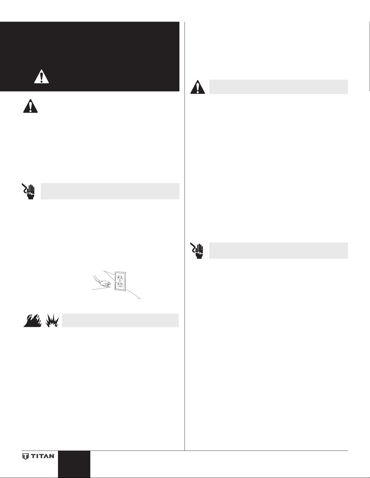
Grounded Outlet
Grounding Pin
Cover for grounded outlet box
Important Safety
Information
Read all safety information before operating
the equipment. Save these instructions.
9. Do not operate light switches, engines, or similar spark producing
products in the spray area.
10. Keep area clean and free of paint or solvent containers, rags, and other
ammable materials.
11. Know the contents of the paint and solvents being sprayed. Read all
Material Safety Data Sheets (MSDS) and container labels provided with
the paints and solvents. Follow the paint and solvent manufacture’s
safety instructions.
12. Fire extinguisher equipment shall be present and working.
WARNING - To reduce the risk of injury:
Indicates a hazardous situation which, if not avoided,
could result in death or serious injury.
To reduce the risks of re or explosion, electrical shock
and the injury to persons, read and understand all
instructions included in this manual. Be familiar with the
controls and proper usage of the equipment.
Grounding Instructions
This product must be grounded. In the event of an electrical short circuit,
grounding reduces the risk of electric shock by providing an escape wire for
the electric current. This product is equipped with a cord having a grounding
wire with an appropriate grounding plug. The plug must be plugged into
an outlet that is properly installed and grounded in accordance with all local
codes and ordinances.
WARNING - Improper installation of the grounding plug
can result in a risk of electric shock.
If repair or replacement of the cord or plug is necessary, do not connect the
green grounding wire to either at blade terminal. The wire with insulation
having a green outer surface with or without yellow stripes is the grounding
wire and must be connected to the grounding pin.
Check with a qualied electrician or serviceman if the grounding instructions
are not completely understood, or if you are in doubt as to whether the
product is properly grounded. Do not modify the plug provided. If the plug
will not t the outlet, have the proper outlet installed by a qualied electrician.
This product is for use on a nominal 120 volt circuit and has a grounding
plug that looks like the plug illustrated below. Make sure that the product is
connected to an outlet having the same conguration as the plug. No adapter
should be used with this product.
1. Always wear appropriate gloves, eye protection, clothing and a
respirator or mask when painting. Hazardous vapors – Paints, solvents,
insecticides, and other materials can be harmful if inhaled or come
in contact with body. Vapors can cause severe nausea, fainting or
poisoning.
2. Do not operate or spray near children. Keep children away from
equipment at all times.
3. Do not overreach or stand on an unstable support. Keep eective
footing and balance at all times.
4. Stay alert and watch what you are doing.
5. Do not operate the unit when fatigued or under the inuence of drugs
or alcohol.
6. Never aim spray gun at any part of the body.
7. Follow all appropriate local, state, and national codes governing
ventilation, re prevention, and operation.
8. The United States Government Safety Standards have been adopted
under the Occupational Safety and Health Act (OSHA). These standards,
particularly part 1910 of the General Standards and part 1926 of the
Construction Standards should be consulted.
9. Use only manufacturer authorized replacement parts. User assumes
all risks and liabilities when using parts that do not meet the minimum
specications and safety devices of the manufacturer.
10. Power cord must be connected to a grounded circuit.
11. Use only recommended Titan FlexSpray components.
12. Do not spray outdoors on windy days.
WARNING - To reduce the risk of electric shock:
1. Always remove turbine before cleaning.
2. Power cord must be connected to a grounded circuit.
3. Never submerge electrical parts, including the turbine.
4. Never expose the equipment to rain. Store indoors.
5. Keep electrical cord plug and spray gun trigger free from paint and
other liquids. Never hold the cord at plug connections to support the
cord. Failure to observe may result in an electrical shock.
1. Do not spray ammable or combustible materials near an open ame,
pilot lights or sources of ignition such as hot objects, cigarettes, motors,
electrical equipment and electrical appliances. Avoid creating sparks
from connecting and disconnecting power cords.
2. Exhaust and fresh air introduction must be provided to keep the air
within the spray area free from accumulation of ammable vapors.
3. Use extreme caution when using materials with a ashpoint below 100°
F (38°C). A uid’s ashpoint is the temperature at which vapors from the
uid could ignite if exposed to a ame or spark.
4. Verify that all containers and collection systems are grounded to
prevent static discharge.
5. Connect to a grounded outlet and use grounded extension cords
(electric models only). Do not use a 3 to 2 adapter.
6. Do not use a paint or solvent containing halogenated hydrocarbons.
Such as chlorine, bleach mildewcide, methylene chloride and
trichloroethane. They are not compatible with aluminum. Contact the
coating supplier about compatibility of material with aluminum.
7. Keep spray area well ventilated. Keep a good supply of fresh air
moving through the area to keep the air within the spray area free
from accumulation of ammable vapors. Keep turbine assembly in well
ventilated area. Do not the spray turbine assembly.
8. Do not smoke in the spray area.
WARNING - To reduce the risk of re or
explosion:
English
Important Electrical Information
Use only a 3-wire extension cord that has a 3-blade grounding plug and a
3-slot receptacle that will accept the plug on the product. Make sure your
extension cord is in good condition.
When using an extension cord, be sure to use one heavy enough to carry the
current your product will draw. An undersized cord will cause a drop in line
voltage resulting in loss of power, overheating and possible damage.
This unit is equipped with a 14 gauge power cord, therefore a 14 gauge or 12
gauge extension cord is required. Do not use more than 100 feet of extension
cord.
If an extension cord is to be used outdoors, it must be marked with the sux
W-A after the cord type designation. For example, a designation of SJTW-A
would indicate that the cord would be appropriate for outdoor use.
2
Page 3

Introduction
Start
Notice:
to Paint
Spraying
Introduction
Function description
The paint spraying system consists of a hand-held, motor-operated
turbine, which provides the spray gun with atomization air
In the spray gun, part of the air from the turbine is used to pressurize
the container. This pressure causes the coating material to be fed
through the suction tube to the uid nozzle where it is then atomized
as it exits the uid nozzle.
All settings necessary for operation (e.g. material volume, air volume)
can be conveniently adjusted directly on the gun, including start/stop
of the turbine by activating the trigger.
Coating material
Coating Materials Suitable for Use
Water-based and solvent based coatings.
Review this page to familiarize yourself with
some general information regarding FLEXSPRAY
paint spraying, including which spray materials
are suitable for use, and how to prepare the
spray material.
Coating Materials Not Suitable for Use
Materials that contain highly abrasive components, caustic solutions
and acidic coating substances. Use extreme caution when using
materials with a ashpoint below 100° F (38°C).
Preparing the coating material
Note: Observe the manufacturer’s instructions for the use of the
coating material on the material container or on the technical data
sheet.
Coating material purity
An absolute pre-condition for the trouble-free operation of the
FLEXSPRAY system is that the coating material is uncontaminated.
If you have doubts as to the purity of the coating material, we
recommend that you rst lter your coating material with a paint
strainer.
3
English
Page 4
Safety
Parts and
Start
Start
Notice:
Components
9
19
20
Review the information on this page to
familiarize yourself with the parts and
components of your unit.
10
11
8
22
23
24
7
6
5
3
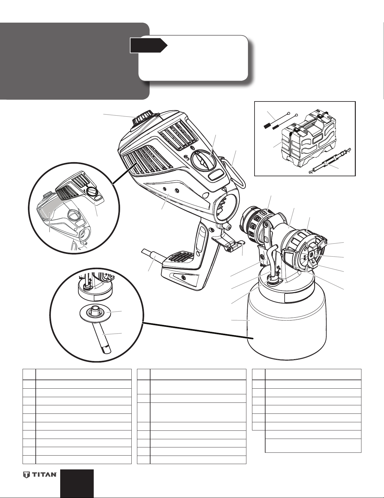
# Description
1 Nozzle
2 Air cap
3 Adjustment lever (pattern width)
4 Adjustment ring (pattern direction)
5 Connecting nut
6 Front end assembly
7 Adjustable material ow control
8 Turbine
9 Variable speed air control knob
10 Air lter cover lock
21
16
15
# Description
11 Shoulder strap hook (can be mounted
on either side of the turbine)
12 Quick Change release lever
13 2-Stage trigger (activates turbine and
then uid needle in order to spray ma-
terial)
14 Material container, 1 Quart
15 Suction tube
16 Container seal
17 Check valve
18 Air tube
13
18
17
14
12
# Description
19 Air lter cover
20 Air lter
21 Power cable
22 Cleaning brush (2)
23 Carry case
24 Shoulder strap
Petroleum jelly, 2cc (not shown)
Velcro strap to wrap power cord (not
shown)
1
2
4
English
4
Page 5
Safety
1a
1b
c
Quick
Start
Start
Notice:
Change
System
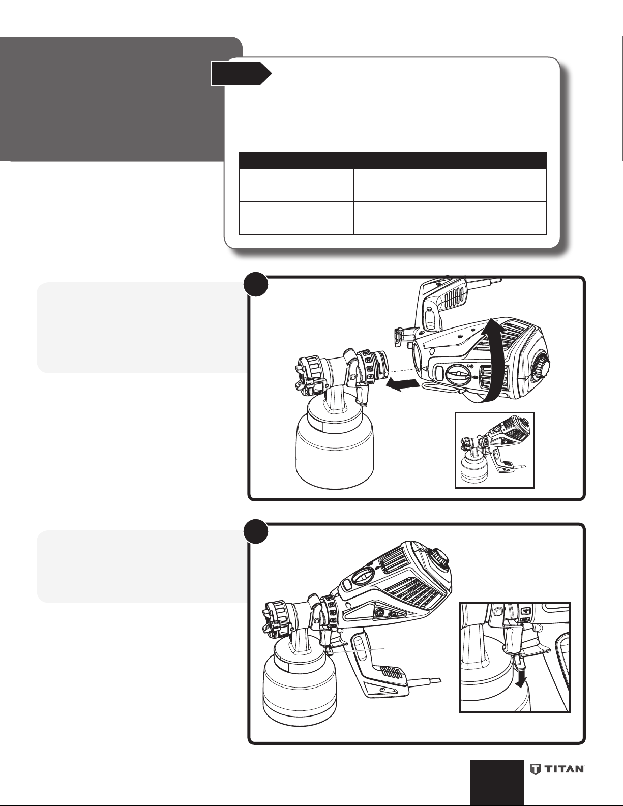
1) To assemble the spray gun:
a. For assembly, insert the front end
assembly into the turbine so that the two
arrows align with each other.
b. Turn the turbine 90° in the arrow direction
until it clicks into place.
With the Quick Change System, the front part of the gun (front end assembly) can
be replaced quickly and easily.
This enables a rapid material change for dierent coatings and larger jobs, and
ensures that the right tool is available for every material and application.
The following front end assemblies are available:
Front End Assembly Description
FlexFinish (white)
Part No. 0529009 (included
with this unit)
FineFinish (red)
Part No. 0529008 (sold
separately)
Spray attachment with slot nozzle and 1 Qt.
stainless steel container. Processes all standard
paints, stains, lacquers and multi-color coatings.
Spray attachment with round nozzle and 1 Qt
stainless steel container. Ideal for low-viscosity
paints, stains and lacquers.
1
2) To disassemble the spray gun:
Push the Quick Change lever below the
trigger (c), twist and separate the front end
assembly from the turbine.
2
5
English
Page 6
Masking
Start
Notice:
Guide
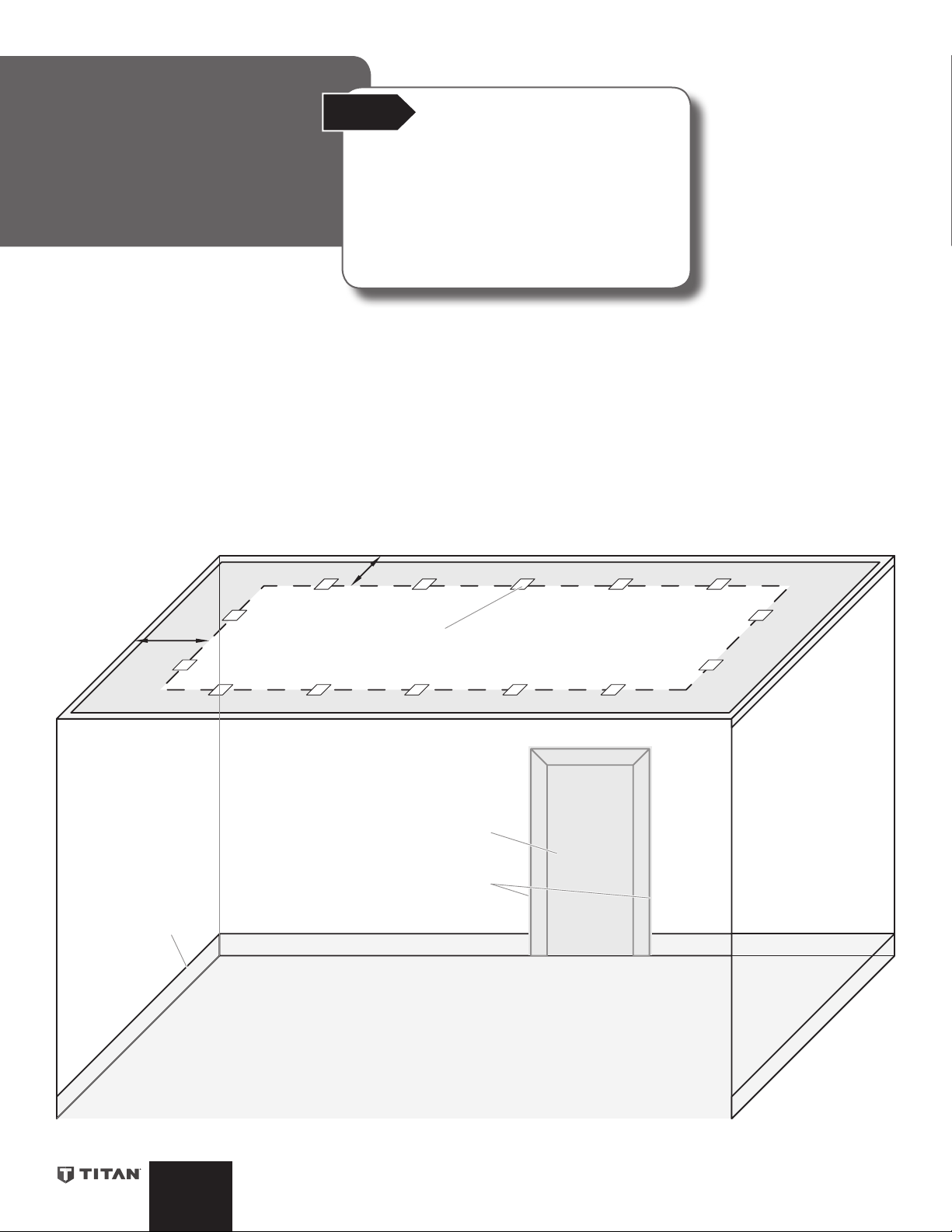
A. If spraying walls, make sure to cover the ceiling no less
than 24” from where the wall and ceiling meet.
B. Use a small piece of masking tape placed every few
feet to secure the covering to the ceiling.
C. Use drop covering to cover the oor and baseboards.
A
If spraying inside a room, follow the guidelines on
this page in order to properly mask anything that
should not be sprayed with paint.
You will need:
• Masking tape
• Plastic covering for walls
• Heavy drop cloth for oors
24”
D. Use masking tape to secure drop covering to
baseboards.
E. Cover any doors or windows with plastic covering.
F. Use masking tape to secure the covering to both sides
of the door or window.
A
24”
A
B
A
E
F
D
C
English
6
Page 7

Setup
1 Quart
b
a
b
Start
Additional instructional items are located inside
the carry case. These items are meant to be
supplements to this instruction manual.
Notice:
IMPORTANT: Before connecting to the
power source, make sure that the power
cord voltage corresponds to the operating
voltage on the rating label. The unit must
be connected with a properly grounded
socket.
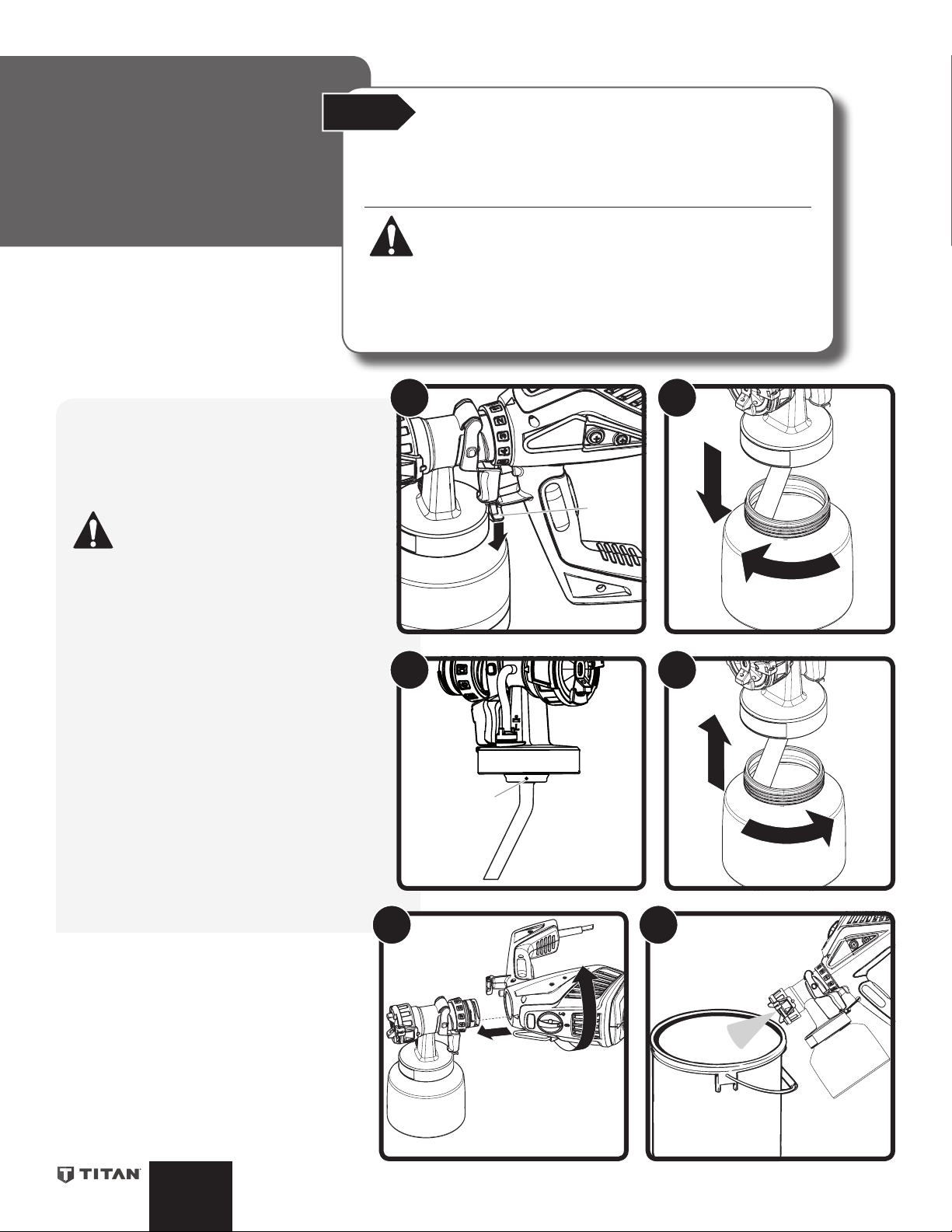
To set up:
1. Unscrew the material container from the
front end assembly.
2. Align the suction tube:
a. If you are going to be spraying in an
upward direction, the angled end of the
suction tube should be pointing toward
the rear of the gun.
b. If you are going to be spraying in a
downward direction, the angled end
of the suction tube should be pointing
toward the front of the gun.
3. Pour in the prepared coating material
(maximum 1 quart).
4. Carefully screw the material container
back onto the front end assembly.
5. Connect front end and turbine.
Plug in the power cord.
The sprayer is now ready for
operation.
1
3
2
4
5
7
English
Page 8
Safety
a
b
1
12
2
d
c
1
2
3
4
5
6
7
8
9
10
11
12
e
f
Setting the
Spray Gun
Controls
NEVER trigger the gun while adjusting the
adjustment ring. NEVER point the spray gun
at any part of the body.
Start
Start
Spray performance will depend upon a number of factors: material thickness, spray
pattern selected, material volume, and air volume. With any type of spray system,
desired spray results will be achieved through some trial and error while adjusting
some or all of these variables.
Review these pages to learn about the spray controls and how they can be used to
acheive the desired spray results.
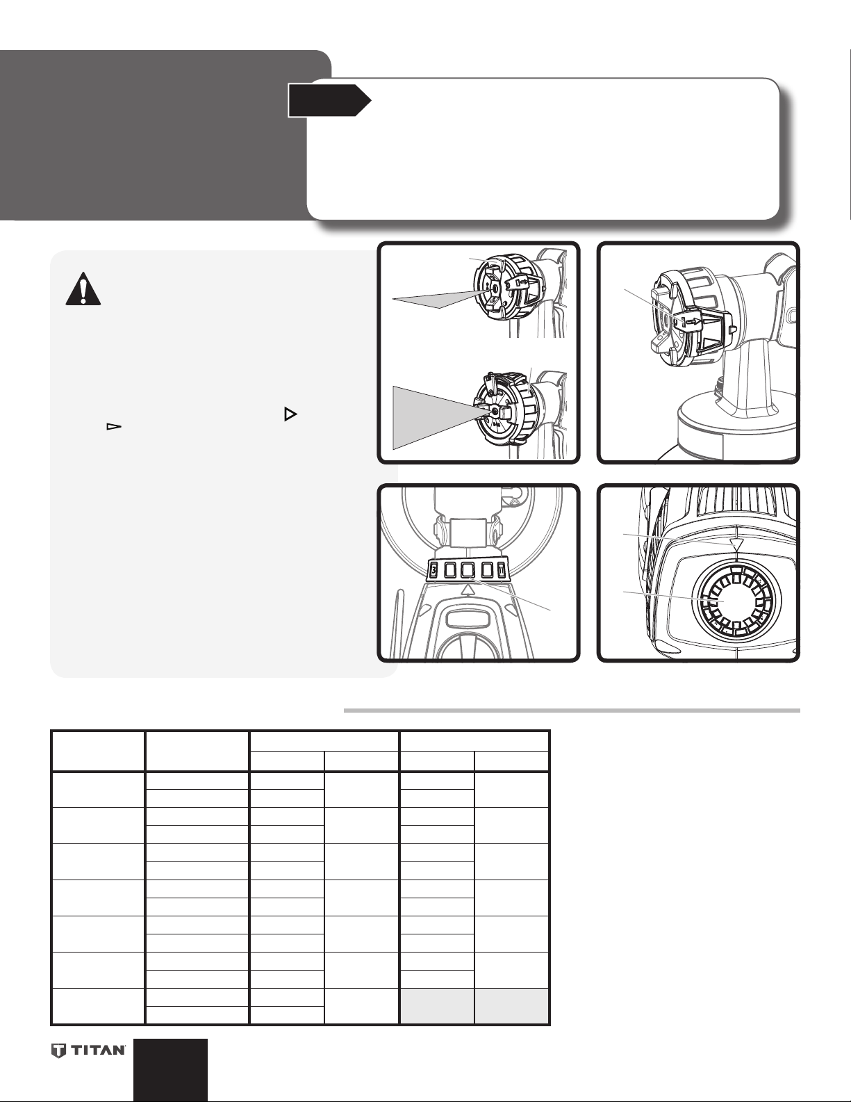
To set the Spray Pattern: (width/direction)
The alignment of the spray pattern can be determined
by turning the adjustment ring (a).
IMPORTANT: Always make sure the connecting nut
(b) is fully tightened before spraying.
It is also possible to switch between a wide ( ) and a
narrow ( ) spray fan pattern with the adjustment lever (c).
To set the Material Flow:
The material ow can be adjusted incrementally from 1
(minimum) to 12 (maximum) by turning the adjustable
material ow control (d). Consult Quick Start Guide
below for a starting point.
Notice:
To set the Air Flow:
Turn the variable speed air control (e) clockwise to
increase the air ow or counter-clockwise to reduce
the air ow (note arrow (f) on body of gun for setting).
Consult Quick Start Guide below for a starting point.
Note: Observe the manufacturer’s instructions for the
use of the coating material on the material container or
on the technical data sheet.
FLEXSPRAY Quick Start Guide
Fan Pattern
Width
1-5 inches 3
5+ inches 6 10
1-5 inches 3
5+ inches 7 10
1-5 inches 2
5+ inches 5 9
1-5 inches 4
5+ inches 8 11
1-5 inches 5
5+ inches 9 11
1-5 inches 4
5+ inches 9 11
1-5 inches 7
5+ inches 10
English
Coating
Stain
Lacquers
Urethanes
Enamels
Acrylic Alkyds
Acrylic Latex
Multi-Color
FlexFinish front end FineFinish front end 1) Start with a fan pattern for painting
Material Air Material Air
5-8
(Medium)
5-8
(Medium)
5-8
(Medium)
9-12
(high)
9-12
(High)
9-12
(High)
5-8
(Medium)
7
7
6
9
9
8
NA NA
9-12
(High)
5-8
(Medium)
5-8
(Medium)
9-12
(High)
9-12
(High)
9-12
(High)
trim work (1-5” width) and larger
surfaces like doors and walls (>5”
width).
2) Adjust Material & Air Flow settings as
shown in chart based on coating, fan
pattern width, and Front End.
3) Fine tune the Material and Air Flow
settings to achieve the best results for
your application.
4) Use narrow pattern for detailed work,
touch up.
5) Recommended settings for Material
and Air Flow may change if the
coating is thinned.
8
Page 9
Safety
Spraying
Before You Begin Spraying
Practice
It is advisable to practice on a piece of scrap wood or cardboard before beginning
on your intended workpiece. A spray poster is also available in the carry case that
can be referenced for additional guidance. Refer to the settings on the FLEXSPRAY
Quick Start Guide, previous page as reference for a starting point.
Surface Preparation
All objects to be sprayed should be thoroughly cleaned before spraying material on
them. Areas not to be sprayed may, in certain cases, need to be masked or covered.
Spray Area Preparation
The spray area must be clean and free of dust in order to avoid blowing dust onto
your freshly sprayed surface.
Start
Start
The room you are spraying must be properly
masked in order to prevent overspray from
coating woodwork, oors or furnishings. Make
sure you have properly masked the room per
the instructions on page 6.
Notice:
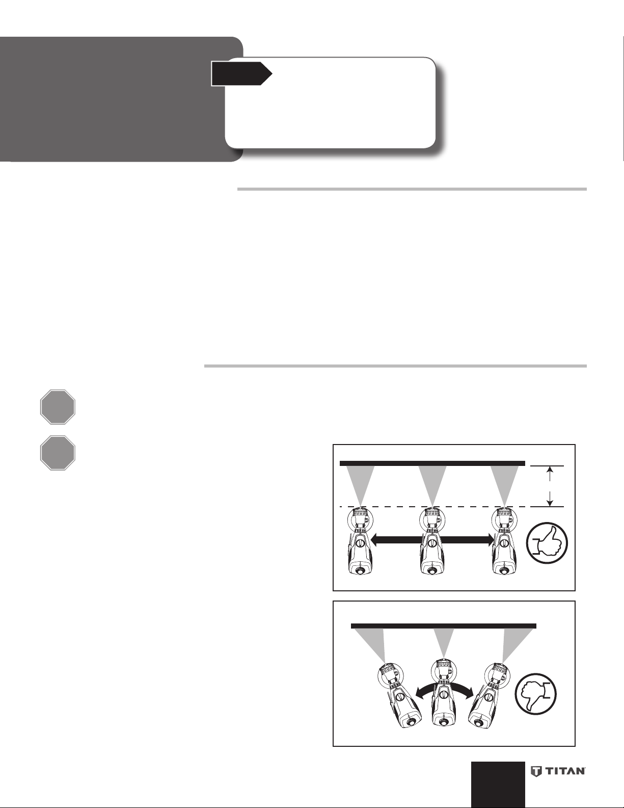
How to Spray Properly
It is important to keep your arm moving whenever the
STOP
STOP
• Position the spray gun perpendicular to and six (6) or more
Note: If spraying trim or some other surface that requires a very
narrow spray pattern, you may need to get closer than 6 inches from
the spray surface.
• Spray parallel to the surface with smooth passes at a consistent
• Always apply a thin coat of material on the rst pass and allow to
• When spraying larger surfaces, overlap each spray pass by at
• When spraying, always trigger the spray gun after spray pass
Note: Between passes, the trigger should be released only far enough
for material to stop spraying, but not enough to cause the turbine to
shut down.
gun is being triggered. If you pause or linger in one
spot too long, too much material will be sprayed to the
surface.
Partially pulling the trigger will start the turbine, but
no material will spray until the trigger is pulled fully.
It is recommended that the trigger rst be pulled
partially in order to start the turbine before a spray
pass is made.
inches from the spray surface, depending upon the spray pattern
size desired.
speed as illustrated, right. Doing this will help avoid irregularities
in the nish (i. e. runs and sags).
dry before applying a second, slightly heavier coat.
least 50% This will ensure full coverage.
has begun and release trigger before stopping the pass. Always
keep the gun pointed squarely at the spray surface.
Even coat throughout
6 -12 inches
1122 1122 1122
Keep stroke smooth and at an even speed
Light coat Heavy coat Light coat
12
1
2
1122
2
1
12
IMPORTANT: When using quick-drying or two-component
coating materials, make sure to clean the sprayer with a suitable
cleaning agent before the material dries or cures inside the spray
gun. Check the manufacturer’s technical data sheet for drying
times.
9
Do not ex wrist while spraying.
English
Page 10
Cleanup
a
b
Start
When cleaning, use the appropriate cleaning solution (warm, soapy water
for latex materials; mineral spirits for oil-based materials)
IMPORTANT: Never clean nozzle or air holes in the spray gun with sharp
metal objects. Do not use solvents or lubricants containing silicone.
Before you begin:
Special cleanup instructions for use with flammable solvents
Use extreme caution when using materials with a flashpoint
below 100° F (38°C):
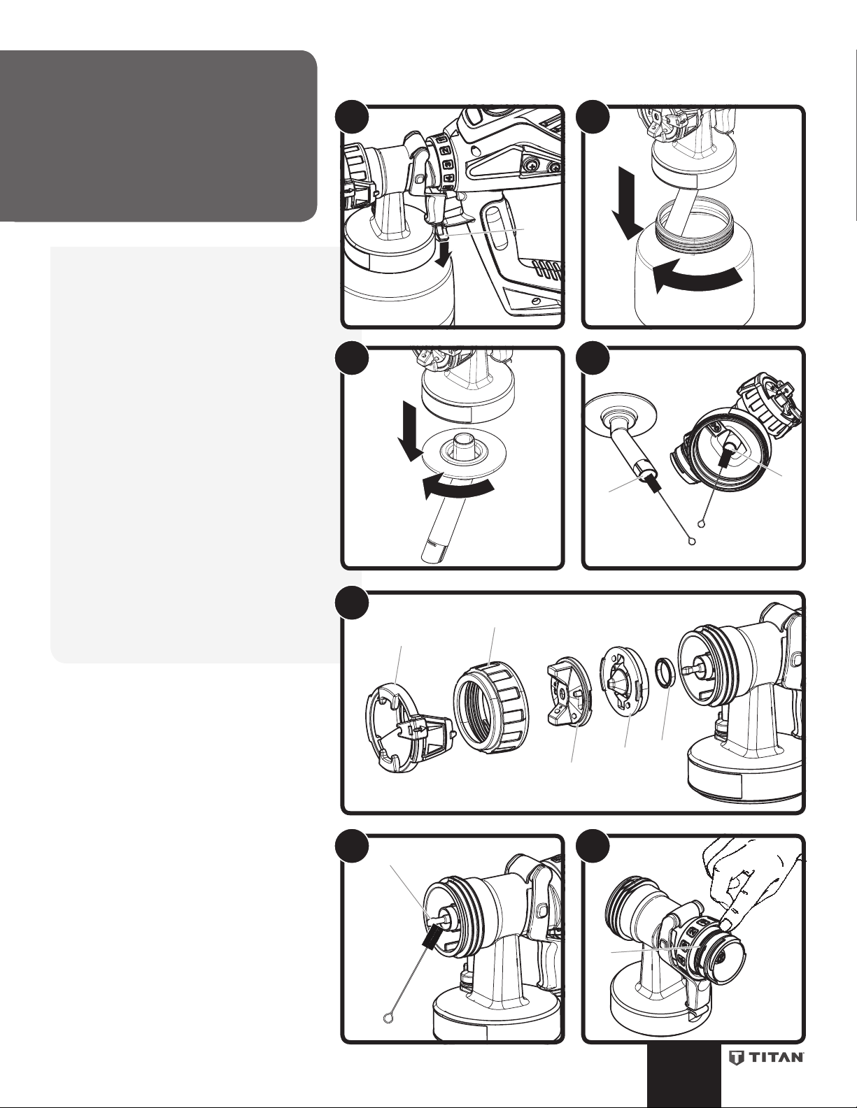
To clean:
1. Unplug the power cord.
Divide the spray gun. Push the Quick-Change
lever below the trigger (a), twist and separate
the front end from the turbine.
Never hold the turbine under water or
immerse it into liquids.
2. Unscrew the container and remove.
Empty any remaining material back into the
material container.
Pre-clean the container and suction tube using
a brush and appropriate cleaning solution.
3. Clean the air vent (b) on the suction tube.
4. Pour a small amount of the appropriate
cleaning solution into the container. Attach
the container to the gun.
5. Connect front end assembly and turbine.
6. Plug in the power cord. Spray the cleaning
solution into a safe area.
Note: If you are spraying into a waste container as
shown, have the spray pattern width set to narrow
to better direct cleaning solution into the waste
container.
Repeat the above procedure until the solvent
or water emerging from the nozzle is clear.
1
3
2
4
Continued on next page
English
65
Empty waste
container
10
Page 11
SafetyCleanup
a
e
f
g
h
i
j
k
c
d
(continued)
7. Unplug the power cord.
Divide the spray gun. Push the Quick-
Change lever below the trigger (a), twist
and separate the front end from the
turbine.
8. Remove the 1 Qt. container and empty it.
9. Remove suction tube with container seal.
10. Clean suction tube (c) and suction nozzle
opening in front end assembly (d) with
cleaning brush.
11. Remove the adjustment ring (e) carefully
from the connecting nut (f). Unscrew
connecting nut (f), remove air cap (g),
nozzle (h) and nozzle seal (i).
Thoroughly clean all parts.
12. Gently clean the end of the needle (j) and
the needle opening with the cleaning
brush.
Wipe the outside of the front end
assembly and material container with a
damp cloth (be sure cloth is damp with
appropriate cleaning solution).
13. Lubricate the O-ring (k) on the rear of the
front end assembly with a thin layer of the
included petroleum jelly.
Move on to “Reassembly”, next page.
7 8
9
11
10
12 13
11
English
Page 12
Reassembly
b
a
c
g
h
i
e
d
f
Start
Follow the steps described below for
reassembly. Improper reassembly can result in
damage to the spray gun assembly.
IMPORTANT:
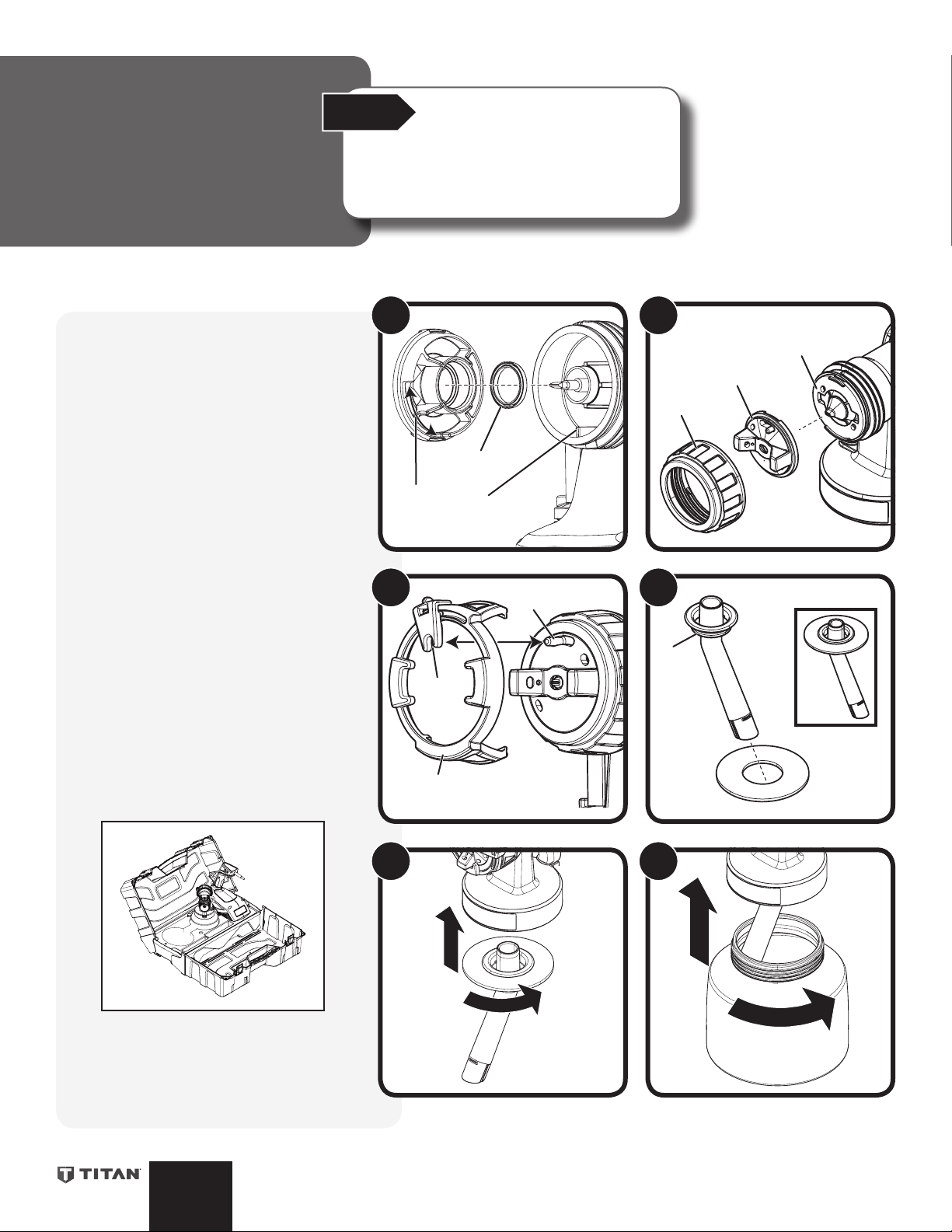
To reassemble:
1. Install the nozzle seal with the groove (a)
(slot) facing toward the nozzle (away from
the front end assembly).
Insert the nozzle. Make sure to align the
groove (b) and notch (c) and align the
nozzle opening with the needle.
2. Put the air cap (d) on the nozzle (e) and
secure with the connecting nut (f).
3. Snap the adjustment ring (g) into the
connecting nut, enabling the adjustment
lever (h) on the peg (i) to be positioned in
the air cap.
Note: Make sure that the two recesses on the
adjustment ring are engaged in the air cap tabs.
4. Place the container seal on the suction
tube and slide it over the collar (j), while
turning the container seal slightly.
5. Insert the suction tube with the container
seal into the front end assembly.
6. Replace container.
Transportation / storage
1. Detach the strap from the sprayer and
secure it to the carry case (it can also be
stored inside the carry case).
2. Place the unit and accessories into the
carry case as shown below and secure with
the elastic straps.
1
3
2
4
j
3. Coil the power cord and use the provided
Note: Press the right and left inside of the case
lid outwards in order to open up the transport
case completely.
velcro strap to secure.
English
5 6
12
Page 13
Maintenance
a
b
d
e
c
a
b
c
c
b
Start
Review the information on this page to familiarize
yourself with the proper way to maintain your
paint sprayer.
Notice:
Air Filter:
IMPORTANT: Never operate the device with a dirty or missing air filter, as dirt
could be sucked in and affect the operation of the turbine and/or contaminate your
material. Always check the air filter before starting work.
1. Unplug the power cord.
2. Turn the lter cover lock (a) to the unlock position. Remove the lter cover (b) and
lter (c).
3. Clean, blow out, or replace the air lter (c).
IMPORTANT: DO NOT clean the filter with any solvent. Use only warm, soapy water
to clean.
4. Replace the cleaned or new lter into the turbine. Make sure the lter is tucked
underneath the housing (d) on both sides of the turbine. Reattach the lter cover
and turn the lter cover lock to the lock position.
Note: Make sure the tabs of the lter cover (e) snap into place on both sides of the
turbine (inset).
Note: When replacing, use only Titan FlexSpray HandHeld lters.
1
2
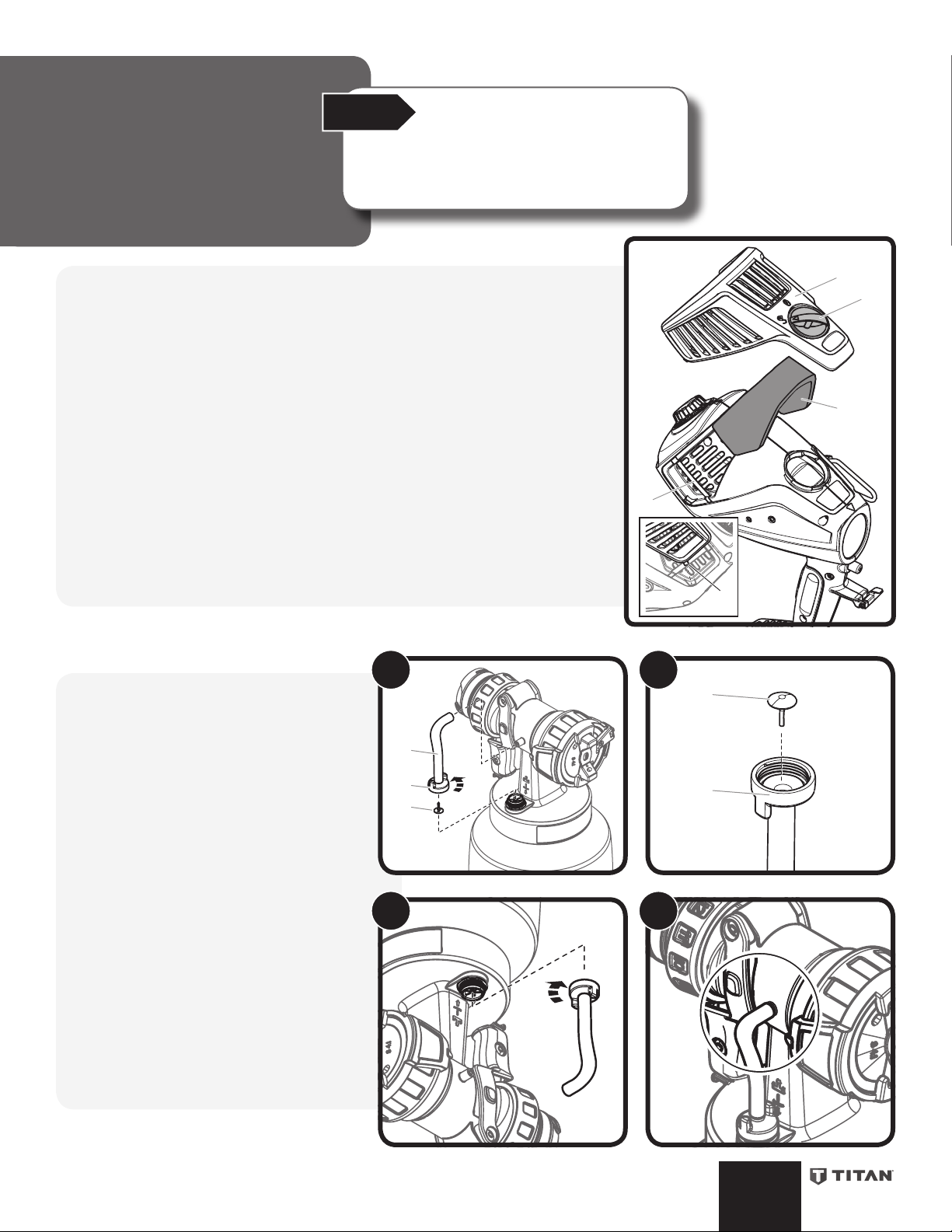
Air Tube:
Note: If paint has entered the air tube, proceed
as follows.
1. Pull the air tube (a) at the top from the
gun body. Screw o the valve cover (b).
Remove the valve seal (c). Clean all the
parts carefully.
IMPORTANT: The air tube and valve seal (c)
are only solvent-resistant to a limited extent.
Do not immerse in solvent, only wipe.
2. Place the valve seal (c) in the valve cover
(b) with the pin facing into the tube.
Note: Installing the valve seal into the valve
cover will be much easier if the valve cover is
inverted.
3. Turn the front end assembly upside down
and screw on the valve cover (with valve
seal inside) from underneath.
Note: Turning the front end assembly upside
down will prevent the valve seal from falling out
of the valve cover during reinstallation.
4. Place the air tube on the valve cover and
on the nipple at the gun body.
3
4
13
English
Page 14
Troubleshooting
Any attempt to open the motor housing or repair any electrical
parts within the unit by anyone other than an authorized repair
technician could cause serious injury and will void the warranty.
Problem Cause Solution
The unit will not run
Little or no material ow
Material leaking
Spray pattern too thick, runs, spits
and sags
Spray jet pulsates
1. The power cord is unplugged, or no power
in outlet
2. Device overheated
1. Nozzle clogged
2. Suction tube clogged
3. Material ow setting too low
4. Suction tube loose
5. No pressure build-up in container
6. Container empty
7. Suction tube lter clogged (if applicable)
8. Air tube loose/damaged
9. Paint container seal damaged
10. Air vent on suction tube blocked
11. Air tube valve seal stuck
12. Air lter clogged
1. Air cap, nozzle or needle dirty
2. Front end assembly attachment incorrectly
assembled
3. Nozzle loose
4. Nozzle seal worn
5. Nozzle worn
6. Needle worn
7. Material build-up on air cap and nozzle
1. Material ow setting too high
2. Air ow setting too low
3. Nozzle clogged
4. Air lter clogged
5. Too little pressure build-up in container
6. Viscosity of material too high
7. Air tube loose/damaged
8. Activating the trigger too quickly
9. Applying too much material
10. Distance from the spray object too small
11. Front end assembly not suitable for spray
material
1. Material in container running out
2. Air lter clogged
3. Nozzle seal worn
4. Suction tube loose
5. Suction tube / suction tube lter clogged
1. Plug the power cord into 120V outlet
2. Unplug the power plug, let the device cool down
approx. 30 minutes, check the air lter, do not cover the
intake slots
1. Clean
2. Clean
3. Increase ow
4. Insert
5. Tighten container
6. Rell
7. Clean or use another lter
8. Re-install or replace (see page 13)
9. Replace
10. Clean (see page 10)
11. Clean (see page 13)
12. Clean or replace
1. Clean
2. Assemble correctly (see page 12)
3. Tighten
4. Replace
5. Replace
6. Use new spray attachment
7. Clean
1. Decrease ow setting
2. Increase air ow setting
3. Clean
4. Clean or replace (see page 13)
5. Tighten container
6. Thin
7. Re-install or replace
8. Pull trigger partially until turbine reaches full power
9. Decrease volume setting or increase movement of spray
gun
10. Increase distance to spray object
11. Use a dierent front end assembly
1. Rell
2. Clean or replace (see page 13)
3. Replace
4. Insert
5. Clean or use another lter
Too much overspray
Paint in the air tube
This unit contains no servicable electrical parts. Do
not attempt to service yourself. Store indoors with
the power cord wrapped and secured with the velcro
strap.
English
1. Gun too far from spray object
2. Too much material applied
3. Air ow setting too high
4. Material has been over-thinned
5. Front end assembly not suitable for spray
material
1. Valve seal dirty
2. Valve seal defective
14
1. Reduce distance
2. Decrease material ow setting
3. Decrease air ow setting
4. Thicken the material by adding more material
5. Use a dierent front end assembly
1. Clean the valve seal (see page 13)
2. Replace the valve seal (see page 13)
Page 15
Manuel de
l’utilisateur
Lire ce manuel pour obtenir des directives complètes
FLEXSPRAY
HANDHELD
Modèle 0524093
Besoin d’aide?
Appelez le service technique Titan
1-800-526-5362
Enregistrement du produit en ligne
sur le site :
www.titantool.com
Table de matières
16 Consignes de sécurité importantes
17 Introduction à la pulvérisation de peinture
18 Pièces et composants
19 Système de changement rapide (Quick Change)
20 Guide pour appliquer du ruban
21 Montage
22 Réglage des commandes du pistolet pulvérisateur
23 Pulvérisation
24 Nettoyage
26 Remontez
27 Entretien
28 Dépannage
44 Liste de pièces
46 Garantie limitée
Français
Page 16

Importantes
Prise trilaire
Broche de mise à la terre
SafetySafety
consignes de sécurité
Lire toutes ces consignes avant d’utiliser
l’appareil. Garder ces consignes
8. Ne fumez pas dans la zone de pulvérisation.
9. N’actionnez pas d’interrupteurs électriques, de moteurs ou autres
dispositifs produisant des étincelles dans la zone de pulvérisation.
10. Maintenez la propreté de la zone et veillez à ce qu’elle ne contienne pas
de conteneurs de peinture ou de solvant, de chions et autres matières
inammables.
11. Sachez ce que contiennent la peinture et les solvants pulvérisés. Lisez
les ches de sécurité du matériel (MSDS) et les étiquettes apposées sur
les conteneurs de peintures et de solvants. Respectez les consignes de
sécurité du fabricant de peinture et de solvant.
12. Ayez un extincteur en bon état de fonctionnement à portée de main.
Indique une situation à risque, laquelle, si elle n’est pas
évitée, peut entraîner des blessures graves, voire la mort.
Pour réduire les risques d’incendie ou d’explosion,
de choc électrique et de blessure, vous devez lire et
comprendre les directives gurant dans ce manuel.
Familiarisez-vous avec les commandes et l’utilisation
adéquate de l’équipement.
Directives sur la mise à la terre
Ce dispositif doit être mis à la terre. En cas de court-circuit, ce procédé
permet de réduire le risque d’un choc électrique en fournissant un parcours
d’évacuation pour le courant. Ce produit est équipé d’un cordon comportant
un l de mise à la terre, et muni d’une che appropriée. Cette che doit être
connectée dans une prise adéquatement installée et mise à la terre selon les
codes et règlements en vigueur.
Une installation inadéquate de la fiche de
mise à la terre risque de provoquer un choc électrique.
S’il est nécessaire de réparer ou de remplacer le cordon ou la che, ne pas
connecter le l de mise à la terre vert à aucune des bornes à broches plates. Le
l comportant un isolant de couleur verte, avec ou sans lignes jaunes, est le l
de mise à la terre devant être connecté à la broche de mise à la terre.
Il est recommandé de consulter un électricien qualié ou un technicien si les
directives sur la mise à la terre ne sont pas entièrement comprises, ou si l’on
n’est pas sûr que le produit soit correctement mis à la terre. Ne pas modier la
che. Si la che ne peut être insérée dans la prise, demander à un électricien
qualié d’installer la prise appropriée.
Ce produit doit être utilisé sur un circuit d’une tension nominale de 120 volts
et comporte une che de mise à la terre semblable à celle illustrée ci-dessous.
Veuillez-vous assurer que le produit est connecté à une prise électrique ayant
la même conguration que la che mâle. Ne pas utiliser d’adaptateur avec ce
produit.
AVERTISSEMENT – Pour réduire le risque de blessure :
1. Portez toujours les gants, la protection oculaire, les vêtements et
un respirateur ou masque appropriés quand vous peignez. Vapeurs
dangereuses – Les peintures, solvants, insecticides et autres matières
peuvent être dangereux s’ils sont inhalés ou entrent en contact avec le
corps. Les vapeurs peuvent provoquer d’importantes nausées, une perte
de connaissance ou un empoisonnement.
2. Ne travaillez pas et ne pulvérisez pas près d’enfants. Éloignez toujours
les enfants de l’équipement.
3. Ne travaillez pas avec les bras au-dessus de la tête ni sur un support
instable. Appuyez-vous bien sur les deux pieds pour toujours conserver
l’équilibre.
4. Soyez attentif et regardez ce que vous faites.
5. N’utilisez pas l’appareil quand vous êtes fatigué ou sous l’inuence de
drogues ou d’alcool.
6. Ne pas pointer le pistolet vers une partie du corps.
7. Observer tous les codes locaux, provinciaux, d’état et nationaux
régissant la ventilation, la prévention des incendies et le
fonctionnement de l’appareil.
8. Aux États-Unis, le gouvernement a adopté des normes de sécurité en
vertu de l’Occupational Safety and Health Act (OSHA). Le cas échéant, on
doit les consulter, notamment les parties 1910 des normes générales et
1926 des normes de construction.
9. N’utiliser que les pièces autorisées par le fabricant; les utilisateurs qui
choisiront d’utiliser des composants dont les caractéristiques techniques
et les exigences en matière de sécurité sont inférieures devront en
assumer tous les risques et responsabilités.
10. Le cordon d’alimentation doit être branché à un circuit trilaire.
11. Utiliser que des piéces recommandée de Titan FlexSpray.
12. Ne pas pulvériser à l’extérieur par grands vents.
AVERTISSEMENT – Pour réduire le risque de de choc électrique :
Plaque murale de la prise
AVERTISSEMENT – Pour réduire le risque
d’incendie ou d’explosion :
1. Ne pulvérisez pas de matières inammables ou combustibles près d’une
amme nue, de voyants lumineux ou de sources d’ignition telles que
des objets chauds, cigarettes, moteurs, matériel et appareils électriques.
Évitez de produire des étincelles en connectant et en déconnectant les
cordons électriques.
2. Veiller à éviter toute accumulation de vapeurs inammables en vous
assurant que la zone où la pulvérisation a lieu est susamment ventilée.
3. S’entourer de toutes les précautions possibles lorsqu’on utilise des
produits ayant un point d’éclair inférieur à 38 °C (100 °F). Le point
d’éclair d’un uide est la température à laquelle les vapeurs émanant du
uide peuvent s’enammer au contact d’une amme ou d’une étincelle.
4. Vériez que tous les conteneurs ou systèmes de stockage sont reliés à la
terre pour éviter les décharges d’électricité statique.
5. Connectez à une prise électrique avec prise de terre et utilisez des
rallonges électriques reliées à la terre. N’utilisez pas d’adaptateur 3 à 2.
6. N’utilisez pas de peinture ou de solvant contenant du halon, par
exemple, le chlore, les agents antimoisissure à l’eau de Javel, le chlorure
de méthylène et le trichloroéthane. Ils ne sont pas compatibles avec
l’aluminium. Contactez le fournisseur de revêtements pour connaître la
compatibilité du matériau avec l’aluminium.
7. La zone de pulvérisation doit toujours être bien aérée. Une bonne
quantité d’air frais doit constamment traverser la zone de pulvérisation
pour éviter les accumulations de vapeurs inammables. Le turbine doit
être placé dans une zone bien aérée. Ne pulvérisez pas le turbine.
1. Retirez toujours la turbine avant le nettoyage.
2. Le cordon d’alimentation doit être branché à un circuit doté d’une mise
à la terre.
3. N’immergez pas les pièces électriques, y compris le turbine.
4. Ne laissez jamais l’appareil sous la pluie. Entreposez-le à l’intérieur.
5. Garder la che du cordon électrique et la détente de l’appareil libres de
toute produits ou de tout autre liquide. Ne jamais exercer de contrainte
sur le raccordement de la che. Le défaut de suivre toutes les directives
énoncées peut provoquer un choc électrique.
Informations importantes sur le
système électrique
Utilisez seulement une rallonge électrique trilaire pourvue d’une prise avec
mise à la terre (trois tiges) et d’une connexion femelle à trois trous convenant au
cordon de l’appareil. Assurez-vous que la rallonge électrique est en bon état.
Lorsque vous utilisez une rallonge électrique, assurez-vous qu’elle a un calibre
assez élevé pour transmettre le courant nécessaire au fonctionnement de
l’appareil. L’utilisation d’une rallonge de calibre trop faible entraîne une chute
de tension sectorielle se traduisant par une perte de courant, une surchaue
de l’appareil et dommage possible.
Cet appareil est équipé d’un cordon d’alimentation de calibre 14, donc un
calibre 14 ou 12 rallonge électrique est nécessaire. Ne pas utiliser plus de 31m
de rallonge électrique.
Si vous devez utiliser une rallonge à l’extérieur, la mention W-A doit y gurer
suivant la désignation du type de rallonge. Par exemple, SJTW-A représente
une rallonge appropriée pour une utilisation à l’extérieur.
Français
16
Page 17

Introduction à la
pulvérisation de
peinture
Introduction
Description de la fonction
Le système de pulvérisation de peinture se compose d’une turbine
motorisée portative qui fournit de l’air de pulvérisation au pistolet de
pulvérisation.
Dans le pistolet de pulvérisation, une partie de l’air de la turbine est
utilisée pour mettre le réservoir en pression. Cette pression alimente le
matériau de revêtement dans le tube d’aspiration à l’embout de liquide
où il est ensuite pulvérisé en sortant.
Tous les réglages nécessaires au fonctionnement (p. ex., volume de
produit, volume d’air) peuvent facilement être réglés directement sur
le pistolet, y compris le démarrage/l’arrêt de la turbine en activant la
détente.
Démarrer
Passez cette page en revue an de vous
familiariser avec certains renseignements
généraux concernant la pulvérisation de
peinture FLEXSPRAY, y compris les produits à
pulvériser convenables et la façon de préparer le
produit à pulvériser.
Avis :
Matériau de revêtement
Matériaux de revêtement appropriés
Revêtements à eau et avec solvant.
Matériaux de revêtement non appropriés
Les matériaux qui contiennent des composantes très abrasives, des
solutions caustiques et des matières de revêtement acides. S’entourer
de toutes les précautions possibles lorsqu’on utilise des produits
ayant un point d’éclair inférieur à 38 °C (100 °F).
Préparation du matériau de revêtement
Remarque : Suivez les consignes du fabricant pour l’utilisation du
matériau de revêtement sur le contenant du matériau ou sur la che
technique.
Pureté du matériau de revêtement
Une condition préalable absolue du fonctionnement sans problème
du système de FLEXSPRAY est que le matériau de revêtement ne
soit pas contaminé. Si vous doutez de la pureté du matériau de
revêtement, nous vous recommandons de ltrer le matériau de
revêtement à l’aide d’un tamis à peintures.
17
Français
Page 18

Pièces et
Démarrer
Avis :
composants
9
19
20
Examinez l’information gurant dans
cette page pour vous familiariser avec
les pièces et les composants de votre
appareil.
10
11
8
22
23
24
7
6
5
3
# Description
1 Embout
2 Chapeau d’air
3
Levier de tarage (largeur de la répartition)
4
Anneau de tarage (direction de la
répartition)
5 Écrou d’assemblage
6 Ensemble avant
7 Réglage du débit de produit
8 Turbine
9 Réglage de l’air à vitesse variable
10 Système de verrouillage de couvercle
de ltre à air
21
16
15
# Description
11 Crochet de la courroie d’épaule (peut
être monté d’un côté ou de l’autre de
la turbine)
12 Levier de dégagement pour le change-
ment rapide
13 Détente à deux étages (active la turbine
et ensuite le pointeau an de pulvériser
le produit)
14 Réservoir de liquide, 1 Qt.
15 Tube d’aspiration
16 Joint d’étanchéité de réservoir
17 Clapet antiretour
13
18
17
14
12
# Description
18 Tube d’air
19 Couvercle de ltre d’air
20 Filtre d’air
21 Cordon d’alimentation
22 Brosse de nettoyage (2)
23 Boîtier de transport
24 Courroie d’épaule
1
2
4
Pétrolatum, 2 cc (non illustré)
Courroie Velcro pour enrouler le cordon
d’alimentation (non illustré)
Français
18
Page 19

Système de
1a
1b
c
changement
rapide (Quick
Change)
1) Montage
a. Pour le montage, insérez l’ensemble avant
dans la turbine an que les deux èches
s’alignent.
b. Tournez la turbine de 90° dans la direction
de la èche jusqu’à ce qu’elle clique en
place.
Démarrer
Grâce au système de changement rapide, la partie avant du pistolet (ensemble avant)
peut être remplacée rapidement et facilement.
Cela permet le changement rapide de produit pour diérents revêtements et les
plus gros travaux. Cela assure également que le bon outil est disponible pour chaque
produit et application.
Les ensembles avant suivants sont vendus :
Ensemble avant Description
FlexFinish (blanc)
Nº de pièce 0529009
(incluse avec cet appareil)
FineFinish (rouge)
Nº de pièce 0529008
(vendue séparément)
1
Avis :
Accessoire de pulvérisation avec embout à fente et
un réservoir en acier inoxydable de 0,9 litre. Pulvérise
toutes les peintures, les teintures, les laques et tous
les revêtements multicolores standards.
Accessoire de pulvérisation avec embout rond et
un réservoir en acier inoxydable de 0,9 litre. Idéal
pour les peintures, les teintures et les laques à faible
viscosité.
2) Démontage
Poussez le levier de changement rapide
sous la détente (c), tournez et séparez
l’ensemble avant de la turbine.
2
19
Français
Page 20

Guide pour
Démarrer
Avis :
appliquer
du ruban
A. Si vous pulvérisez les murs, assurez-vous de couvrir
le plafond au moins 60 cm à partir du bord où se
joignent le mur et le plafond.
B. Utilisez un petit morceau de ruban-cache placé
chaque quelques pieds pour xer le revêtement au
plafond.
C. Utilisez une toile de protection pour couvrir le
plancher et les plinthes.
Si vous pulvérisez à l’intérieur d’une pièce, suivez les
directives gurant sur cette feuille an de masquer
correctement les choses qui ne devraient pas être
peintes.
Vous aurez besoin de ce qui suit :
• Ruban-cache
• Revêtement en plastique pour les murs
• Toile de protection résistante pour les planchers
A
24”
D. Utilisez du ruban-cache pour xer la toile de
protection aux plinthes.
E. Couvrez les portes ou les fenêtres d’un revêtement en
plastique.
F. Utilisez du ruban-cache pour xer le revêtement aux
deux côtés de la porte ou de la fenêtre.
A
24”
A
B
A
E
F
D
C
Français
20
Page 21

Montage
1 Quart
b
a
b
Démarrer
Des instructions supplémentaires se trouvent à
l’intérieur du boîtier de transport. Ces directives
constituent un complément de ce manuel
d’instructions.
Avis :
IMPORTANT : Avant de brancher l’appareil
à la source d’alimentation, s’assurer
que la tension du cordon d’alimentation
correspond à la tension de fonctionnement
gurant sur l’étiquette de tension.
L’appareil doit être branché à une prise
correctement mise à la terre.
Montage :
1. Dévisser le réservoir de peinture de
l’ensemble avant.
2. Aligner le tube d’aspiration.
a. Si vous prévoyez diriger le jet vers
le bas, il faut alors pointer la partie
angulaire du tube d’aspiration vers
l’avant du pisolet.
b. Par contre, si vous prévoyez diriger
le jet vers le haut, vous devez alors
pointer le bout angulaire du tube
d’aspiration vers l’arrière du pistolet.
3. Vider le revêtement préparé (maximum
de 0,9 livre) dans le réservoir.
4. Visser soigneusement le réservoir de
peinture sur l’ensemble avant.
5. Raccorder l’ensemble avant et la turbine.
Brancher le cordon d’alimentation.
Le pistolet de pulvérisation est maintenant
prêt à être utilisé.
1
3
2
4
5
21
Français
Page 22

Réglage des
a
b
1
12
2
d
c
1
2
3
4
5
6
7
8
9
10
11
12
e
f
Démarrer
commandes
du pistolet
pulvérisateur
N’APPUYEZ JAMAIS sur la gâchette du pistolet
pendant que vous êtes en train de régler le
anneau de tarage. NE POINTEZ JAMAIS le
pistolet pulvérisateur vers l’une ou l’autre des
parties de votre corps.
Régler la répartition de pulvérisation :
(largeur/direction)
On peut déterminer l’orientation de la répartition de
pulvérisation en tournant l’anneau de tarage (a).
IMPORTANT : Toujours veiller à ce que l’écrou de
connexion (b) soit bien serré avant la pulvérisation.
Il est également possible de passer d’une répartition de
peinture en forme d’éventail large (
du levier de réglage (c).
Régler le débit du produit :
On peut régler le débit du produit progressivement de 1
(minimum) à 12 (maximum) en tournant le réglage du débit
de produit (d). Consulter le guide de démarrage rapide pour
établir un point de départ.
) et étroite ( ) à l’aide
Le rendement dépendra d’un certain nombre de facteurs: l’épaisseur du produit,
la répartition de pulvérisation sélectionnée, le volume du produit et la volume de
l’air. Avec n’importe quel type de systeme de pulvérisation, on peut obtenir les
résultats désirés par essais et erreurs pendant le réglage de certaines ou de toutes
ces variables.
Étudiez ces pages pour vous renseigner sur les commandes de pulvérisation et la
façon dont elles peuvent être utilisées pour obtenir les résultats désirés.
Avis :
Régler le débit d’air :
Tourner le réglage de l’air à vitesse variable (e) dans le sens
des aiguilles d’une montre an d’augmenter le débit d’air ou
dans le sens inverse des aiguilles d’une montre an de réduire
le débit d’air (remarquer la èche (f) sur le corps du pistolet
pour le réglage). Consulter le guide de démarrage rapide pour
établir un point de départ.
Remarque : Suivre les directives du fabricant quant à
l’utilisation du matériau de revêtement sur le réservoir de
peinture ou sur la che de données techniques.
Guide de démarrage rapide FLEXSPRAY
Largeur de la
Revêtement
Teinture
Lacques
Uréthanes
Émails
Teintures
Acryliques/Alkydes
Émulsion
Acrylique
Multicolores
Répartition en
forme d’éventail
2,5 à 12,5 cm 3
Plus de 12,5 cm 6 10
2,5 à 12,5 cm 3
Plus de 12,5 cm 7 10
2,5 à 12,5 cm 2
Plus de 12,5 cm 5 9
2,5 à 12,5 cm 4
Plus de 12,5 cm 8 11
2,5 à 12,5 cm 5
Plus de 12,5 cm 9 11
2,5 à 12,5 cm 4
Plus de 12,5 cm 9 11
2,5 à 12,5 cm 7
Plus de 12,5 cm 10
Français
Application Frontale FlexFinish Application Frontale FineFinish
Produit Air Produit Air
5-8
(Moyen)
5-8
(Moyen)
5-8
(Moyen)
9-12
(Élevé)
9-12
(Élevé)
9-12
(Élevé)
5-8
(Moyen)
7
7
6
9
9
8
NA NA
22
9-12
(Élevé)
5-8
(Moyen)
5-8
(Moyen)
9-12
(Élevé)
9-12
(Élevé)
9-12
(Élevé)
(1) Commencez avec une répartition
en forme d’éventail pour peindre les
garnitures (largeur de 2,5 à 12,5 cm)
et les plus grandes surfaces comme
les portes et les murs (largeur de >
12,5 cm).
(2) Réglez les paramètres du produit
et du volume d’air comme illustré
dans le tableau, en fonction du
revêtement, de la largeur de la
répartition en forme d’éventail et
l’application frontale.
(3) Réglez les paramètres du produit
et du volume d’air an d’obtenir les
meilleurs résultats pour votre projet.
(4) Optez pour la répartition circulaire
pour le travail détaillé ou les
retouches.
(5) Les paramètres recommandés pour
le produit et le volume d’air peuvent
changer si le revêtement est dilué.
Page 23

Pulvérisation
Démarrer
La pièce à pulvériser doit être bien masquée an
de prévenir que la surpulvérisation ne couvre la
boiserie, les planchers ou les meubles. Assurezvous de bien masquer la pièce conformément
aux directives du « Guide pour appliquer un
ruban »., page 20.
Avis :
Avant de commencer la pulvérisation
Practiquer
Si vous suggérons de vous pratiquer sur un bout de bois ou de carton avant de commencer à pulvériser la surface ou
l’objet proprement dit. Une ache de pulvérisation est également inclusse dans le boîtier de transport. Cette ache
peut être consultée pour obtenir des conseils supplémentaires. Consulter les réglages du guide de démarrage rapide
FLEXSPRAY à la page précédente pour établir un point de départ.
Préparation de la surface
Tous les objets à pulvériser doivent être nettoyés à fond avant de recevoir une première couche. Dans certains cas, il
faudra recouvrir d’un rubancache les parties ne devant pas être pulvérisées.
Préparation de la zone de pulvérisation
Si les travaux de pulvérisation doivent avoir lieu à l’intérieur, la zone de pulvérisation doit alors être propre et exempte
de poussière pour éviter que cette dernière ne se retrouve sur la surface fraîchement peinte à cause du jet d’air.
Méthode de pulvérisation conseillée
Il est important de garder votre bras en mouvement
STOP
STOP
• Placez le pistolet perpendiculairement par rapport à la surface
Remarque : Il peut être nécessaire de se rapprocher à moins de 15 cm
de la surface à pulvériser pour la pulvérisation de garnitures ou d’autres
surfaces exigeant une répartition de pulvérisation très étroite.
• Il faut maintenir le jet parallèle à la surface et le mouvement du bras
• Le premier jet doit toujours servir à l’application d’une mince couche
• Pendant la pulvérisation de plus grandes surfaces, chevaucher
• Lors de l’application, appuyez toujours sur la gâchette après avoir
Remarque : Entre les coups de peinture, il faut seulement libérer la
détente susamment pour arrêter la pulvérisation du produit, mais pas
assez pour arrêter la turbine.
lorsque vous appuyez sur la détente du pulvérisateur. Si
vous arrêtez à un endroit trop longtemps, trop de produit
sera pulvérisé à la surface.
Activation partielle du gâchette va commencer la turbine,
mais pas la matière se vaporiser jusqu’à ce que la gâchette
est appuyez complètement. il est recommandé que la
gâchette intially être activé partiellement de manière à
démarrer la turbine avant une passe de pulvérisation est
eectué.
à pulvériser, à une distance de 15 cm (6 po) ou plus selon la
conguration de jet souhaitée.
doit être uniforme et constant, comme le montre sur la droite. On
évitera ainsi les irrégularités du ni telles que les dégoulinades et la
formation de rideaux.
qu’on laisse ensuite sécher avant de passer une deuxième fois pour
appliquer une couche un peu plus épaisse.
chaque pulvérisation par au moins 50 %. Cela assurera une
couverture complète.
amorcé le mouvement, et relâchez-la avant la n du mouvement.
Un balayage de 50 cm (20 po) produira de meilleurs résultants.
Maintenez toujours le pistolet bien droit par rapport à la surface à
pulvériser.
Couche uniforme partout
De 15 à 30 cm
1122 11221122
Mouvement régulier à vitesse constante
Couche minceCouche épaisse Couce mince
12
1
2
1122
2
1
12
Ne pas échir le poignet
IMPORTANT : Lorsqu’on utilise des matériaux de revêtement
à séchage rapide ou à deux composantes, s’assurer de
nettoyer le pulvérisateur avec un produit de nettoyage
convenable avant que le matériau sèche ou durcisse à
l’intérieur du pistolet de pulvérisation. Vérier la che de
données techniques du fabricant pour le temps de séchage.
23
Français
Page 24

Nettoyage
a
b
Démarrer
Pour le nettoyage, utilisez la solution de nettoyage appropriée (eau chaude, savonneuse
pour les peintures aux latex; essences minérales pour les peintures à l’huile)
IMPORTANT : Ne jamais nettoyer la buse ou l’alésage d’air du pistolet avec des
objets métalliques pointus. N’utilisez pas de solvants ou de lubriants au silicone.
Avant de commencer :
Directives spéciales pour le nettoyage au moyen de solvants
inflammables. S’entourer de toutes les précautions possibles lorsqu’on
utilise des produits ayant un point d’éclair inférieur à 38 °C (100 °F) :
Nettoyage :
1. Debrancher le cordon d’alimentation.
Diviser le pistolet de pulvérisation. Poussez le
levier de changement rapide sous la détente
(a), tournez et séparez l’ensemble avant de la
turbine.
Ne jamais tenir la turbine sous l’eau ou
les immerger dans des liquides.
2. Dévisser le réservoir et retirez.
Vider le reste du matériel dans le contenant du
produit.
Nettoyer le réservoir et le tube d’aspiration à
l’aide d’une brosse et la solution de nettoyage
appropriée.
3. Nettoyer l’ouverture d’aération (b) sur le tube
d’aspiration.
4. Vider une petite quantité de la solution
appropriée de nettoyage dans la réservoir.
Fixer le réservoir au pistolet.
5. Raccorder l’ensemble avant et la turbine.
6. Brancher le cordon d’alimentation. Vaporiser la
solution en utilisant le pistolet dans un endroit
sécuritaire.
Remarque : Il est préférable de régler la
pulvérisation à un mode de répartition étroite an
de mieux diriger la solution de nettoyage dans le
contenant de vidange.
Répéter la procédure ci-dessus jusqu’à ce que
le solvant ou l’eau qui sort de l’embout soit
propre.
Suite à la page suivante
1
3
2
4
65
Français
24
Récipient à
déchets vide
Page 25

SafetyNettoyage
a
e
f
g
h
i
j
c
d
k
(suite)
7. Debrancher le cordon d’alimentation.
Diviser le pistolet de pulvérisation.
Poussez le levier de changement rapide
sous la détente (a), tournez et séparez
l’ensemble avant de la turbine.
8. Retirer le réservoir de 0,9 litre et le vider.
9. Retirer le tube d’aspiration avec le joint
d’étanchéité du réservoir.
10. Nettoyer le tube d’aspiration (c) et
l’ouverture de l’embout d’aspiration de
l’ensemble avant (d) à l’aide de la brosse
de nettoyage.
11. Retirer l’anneau de réglage (e)
soigneusement de l’écrou de connexion
(f). Dévisser l’écrou de connexion (f), retirer
le chapeau d’air (g), l’embout (h) et le joint
d’étanchéité de l’embout (i).
Bien nettoyer toutes les pièces.
12. Nettoyer doucement le bout du pointeau
(j) et l’ouverture du pointeau à l’aide de la
brosse de nettoyage.
Essuyer l’extérieur de l’ensemble avant
et du réservoir de peinture à l’aide d’un
linge humide (s’assurer que le linge
est humidié en utilisant la solution de
nettoyage appropriée).
13. Lubrier le joint torique (k) à l’arrière de
l’ensemble avant d’une couche mince du
pétrolatum inclus.
7 8
9
11
10
Passer à la section « Remontage » à la
prochaine page.
12
25
13
Français
Page 26

Remontez
b
a
c
g
h
i
e
d
f
Démarrer
Suivre les étapes décrites ci-dessous pour le
remontage. Un mauvais remontage risque
d’endommager le pistolet de pulvérisation.
IMPORTANT :
Remontez :
1. Insérer d’abord l’embout d’étanchéité
(a)avec rainure (fente) dans l’embout
(éloigné de l’ensemble avant).
Insérer l’embout. S’assurer d’aligner la
gorge (b) et l’encoche (c) et d’aligner
l’embout avec le pointeau.
2. Disposer le chapeau à air (d) sur l’embout
(e) et xer en serrant à fond l’écrou
d’assemblage (f).
3. Clipser la anneau de tarage (g) sur l’écrou
d’assemblage en veillant à disposer
l’oeillet sur le téton (i) du chapeau à air.
Remarque : S’assurer que les deux gorges sur
l’anneau de réglage sont engrenées dans les
onglets du chapeau d’air.
4. Placer le joint d’étanchéité du réservoir
sur le tube d’aspiration et le glisser sur la
bague (j), tout en tournant légèrement le
joint d’étanchéité du réservoir.
5. Insérer le tube d’aspiration avec le joint
d’étanchéité du réservoir dans l’ensemble
avant.
6. Replacer le réservoir.
Transport/entreposage
1. Détachez la courroie du pulvérisateur et
xez-la au boîtier de transport (elle peut
également être entreposée dans le boîtier
de transport).
2. Placez l’appareil et les accessoires dans
le boîtier de transport tel qu’illustré cidessous et xez-les à l’aide d’élastiques.
1
3
2
4
j
3. Enroulez le cordon d’alimentation et
Remarque : Appuyez à l’intérieur du couvercle
du boîtier à droite et à gauche vers l’extérieur
an d’ouvrir complètement le boîtier de
transport.
utilisez la courroie Velcro pour le xer.
Français
5 6
26
Page 27

Entretien
a
b
c
c
b
a
b
d
e
c
Démarrer
Passer en revue l’information gurant sur cette
page an de vous familiariser avec la bonne façon
d’entretenir votre pulvérisateur.
Avis :
Filtre d’air:
IMPORTANT : Ne jamais utiliser l’appareil avec un ltre d’air sale ou manquant,
étant donné que la saleté peut être aspirée et peut avoir une incidence sur le
fonctionnement de la turbine et/ou contaminer le produit. Il faut toujours vérier
le ltre d’air avant de commencer la pulvérisation.
1. Débrancher l’appareil.
2. Tournez le verrou du couvercle de ltre (a) à la position de déverrouillage. Retirez le
couvercle de ltre (b) et le ltre (c).
3. Nettoyer, souer ou remplacer le ltre d’air (c).
IMPORTANT : NE PAS nettoyer le ltre avec un solvant. Nettoyez avec de l’eau
chaude et savonneuse seulement.
4. Replacez le ltre nettoyé ou le nouveau ltre dans la turbine. Assurez-vous que
le ltre est glissé sous le logement (d) des deux côtés de la turbine. Raccordez
le couvercle de ltre et tournez le verrou du couvercle de ltre à la position de
déverrouillage.
Remarque : Assurez-vous que les onglets du couvercle de ltre (e) s’enclenchent sur la
turbine (schéma en médaillon).
Remarque : Lors du remplacement, utiliser uniquement des ltres de TITAN FLEXSPRAY
HANDHELD .
1
2
Tube d’air:
Remarque : Si de la peinture s’est introduite
dans le tube d’air, suivre les étapes suivantes.
1. Tirer le tube d’air (a) sur le dessus du
corps du pistolet. Dévisser le couvercle de
soupape (b). Retirer le joint de soupape (c).
Nettoyer soigneusement toutes les pièces.
IMPORTANT : Le tube d’air et le joint de
soupape (c) résistent aux solvants dans
une mesure limitée uniquement. Ne pas
les immerger dans du solvant, les essuyer
uniquement.
2. Placer le joint de soupape (c) dans le
couvercle de soupape (b) avec le goujon
face au tube.
Remarque : Installer le joint de soupape dans le
couvercle de soupape sera beaucoup plus facile
si ce dernier est inversé.
3. Retourner l’ensemble avant et visser le
couvercle de soupape (avec le joint de
soupape à l’intérieur) du dessous.
Remarque : Retourner l’ensemble avant
empêchera le joint de soupape de tomber du
couvercle de soupape pendant le remontage.
4. Placer le tube d’air sur le couvercle de
soupape et sur le raccord du corps du
pistolet.
3
4
27
Français
Page 28

Dépannage
Toute tentative par une personne autre qu’un technicien autorisé
d’ouvrir le carter du moteur ou de réparer un composant électrique
pourrait entraîner des blessures graves et annulerait la garantie.
Probleme Cause Solution
La turbine ne dèmarre pas
Débit de produit faible ou
inexistant
Fuite du produit
La répartition de pulvérisation
est trop épaisse et coule
Pulsation du jet
Surpulvérisation excessive
Peinture dans le tube d’air
1. Le cordon d’alimentation n’est pas branché ou la
prise n’est pas alimentée
2. L’appareil s’est surchaué
1. Buse est encrassé
2. Tube d’aspiration est encrassé
3. Débit matériel plaçant si bas (-)
4. Tube d’aspiration est desserré.
5. Il n’y a pas de pression d’air dans le réservoir.
6. Le réservoir est vide
7. Le ltre du tube d’aspiration est bouché (s’il y a lieu)
8. Le tube d’air est desserré/endommagé
9. Le joint d’étanchéité du réservoir de peinture est
endommagé
10. L’ouverture d’aération du tube d’aspiration est
bloquée
11. Le joint de soupape du tube d’air est coincé
12. Filtre à air est encrassé.
1. Le chapeau d’air, l’embout ou le pointeau est sale
2. L’accessoire de l’ensemble avant est mal installé
3. Buse deserré
4. Le joint d’étanchéité de la buse est usé
5. Buse usée
6. Le pointeau est usé
7. Accumulation de produit sur le chapeau d’air et
l’embout
1. Débit de produit trop élevé
2. Débit d’aire trop basse
3. Buse est encrassé
4. Filtre à air est encrassé
5. Il n’y a pas de pression d’air dans le réservoir.
6. Viscosité trop élevée du produit de revêtement.
7. Le tube d’air est desserré/endommagé
8. Le déclencheur est activé trop rapidement
9. L’application du produit est trop abondante
10. Le pistolet n’est pas assez loin de l’objet à pulvériser
11. L’ensemble avant ne convient pas au produit à
pulvériser
1. Épuisement du produit dans le réservoir.
2. Filtre à air est encrassé.
3. Le joint d’étanchéité de la buse est usé
4. Tube d’aspiration est desserré.
5. Le tube d’aspiration/ltre du tube d’aspiration est
bloqué
1. Le pistolet pulvérisateur est trop éloigné de la
surface
2. Apport excessif de produit
3. Débit d’aire trop élevé
4. Le produit a été trop dilué
5. L’ensemble avant ne convient pas au produit à
pulvériser
1. Le joint de soupape est sale
2. Le joint de soupape est défectueux
1. Brancher le cordon d’alimentation dans une prise de 120 V
2. Débrancher l’appareil. Laisser l’appareil se refroidir
pendant environ 30 minutes, ne pas plier le tuyau,
vérier le ltre d’air, ne pas couvrir les fentes d’entrée
1. La nettoyer
2. La nettoyer
3. Augmenter l’arrangement matériel de débit (+)
4. Insérer
5. Bien visser le réservoir
6. Remplir le réservoir
7. Nettoyer ou remplacer le ltre
8. Installer à nouveau ou remplacer le tube d’air (voir la page 27)
9. Remplacer le réservoir de peinture
10. Nettoyer l’ouverture (voir la page 24)
11. Nettoyer le pistolet (voir la page 27)
12. La nettoyer ou remplacer
1. Nettoyer les pièces
2. Installer l’accessoire correctement (voir la page 26)
3. La serrer
4. La remplacer
5. La remplacer
6. Utiliser un nouvel accessoire de pulvérisation
7. Nettoyer les pièces
1. Diminuer l’arrangement matériel de débit (-)
2. Augmenter le réglage d’aire.
3. La nettoyer
4. La nettoyer ou remplacer (page 27)
5. Bien visser le réservoir
6. Le diluer
7. Installer à nouveau ou remplacer le tube d’air (voir la page 27)
8. Appuyer sur la gâchette jusqu’à ce que partiellement
atteint turbine à pleine puissance
9. Réglez le débit du liquide (-) ou encore augmentez le
mouvement du pisolet pulvérisateur.
10. Éloigner le pulvérisateur de l’objet à pulvériser
11. Utiliser un diérent ensemble avant
1. Remplissez
2. La nettoyer ou remplacer (page 27)
3. La remplacer
4. Insérer
5. Nettoyer ou remplacer le ltre
1. Réduire la distance
2. Diminuer l’arrangement matériel de débit (-)
3. Diminuer le débit d’aire
4. Épaissir le produit en en ajoutant plus
5. Utiliser un diérent ensemble avant
1. Nettoyer le joint de soupape (voir la page 27)
2. Remplacer le joint de soupape (voir la page 27)
Cet appareil n’a aucune pièce électrique utilisable. Ne tentez pas
d’effectuer vous-même l’entretien. Rangez, à l’intérieur, avec le
cordon d’alimentation enroulé et fixez-le à l’aide d’une courroie
Velcro.
Français
28
Page 29

Manual de usario
Lea este manual para obtener las instrucciones
completas
FLEXSPRAY
HANDHELD
Modelo 0524093
¿Necesita ayuda?
Llame Titan Technical Service al:
1-800-526-5362
Regístrelo del producto en línea en:
www.titantool.com
Tabla de contenido
30 Información importante sobre seguridad
31 Introducción a la pulverización de pintura
32 Piezas y componentes
33 Sistema de cambio rápido (Quick Change)
34 Guía de protección con cinta adhesiva
35 Preparación
36 Ajuste de los controles de la pistola pulverizadora
37 Rociado
38 Limpieza
40 Reensamblaje
41 Mantenimiento
42 Solución de problemas
44 Lista de piezas
47 Garantía Limitada
Page 30

Información Importante
Receptáculo conectado a tierra
Espiga de conexión a tierra
Tapa de la caja de receptáculo conectada a tierra
SafetySafety
sobre Seguridad
Lea toda la información de seguridad
antes de operar el equipo. Guarde estas
insturcciones.
Indica una situación peligrosa que, de no evitarse, puede
causar la muerte o lesiones graves.
Para reducir los riesgos de incendios, explosiones,
descargas eléctricas o lesiones a las personas, lea y
entienda todas las instrucciones incluidas en este
manual. Familiarícese con los controles y el uso adecuado
del equipo.
Instrucciones para la conexión a tierra
Este producto debe conectarse a tierra. En caso de un cortocircuito eléctrico,
la conexión a tierra reduce el riesgo de choque eléctrico al aportar un alambre
de escape para la corriente eléctrica. Este producto está equipado con un cable
que tiene alambre a tierra con un enchufe a tierra adecuado. Debe usarse el
enchufe para conectar a un receptáculo que esté debidamente instalado y
conectado a tierra en conformidad con los códigos y las ordenanzas locales.
ADVERTENCIA - La instalación incorrecta del enchufe a
tierra puede ocasionar un riesgo de choque eléctrico.
Si es necesario reparar o cambiar el cable o el enchufe, no conecte el cable
verde a ninguna de las dos puntas planas. El cable con aislamiento de color
verde por fuera con o sin rayas amarillas es el alambre de conexión a tierra y
debe conectarse a la espiga de conexión a tierra.
Consulte a un electricista o técnico de servicio capacitado si las instrucciones
para la conexión a tierra no se entienden claramente o si tiene dudas en
cuanto a que el producto esté debidamente conectado a tierra. No modique
el enchufe que se incluye. Si el enchufe no encaja en el receptáculo, pida a un
electricista capacitado que instale un receptáculo adecuado.
Este producto es para utilizarse en un circuito de 120 voltios nominales y
tiene un enchufe a tierra que tiene un aspecto similar al ilustrado más abajo.
Asegúrese que el producto esté conectado a un tomacorriente que tenga la
misma conguración que el enchufe. No deben utilizarse adaptadores para
este producto.
7. Mantenga la zona de pulverización bien ventilada. Asegúrese de que
circula aire fresco por la zona para evitar que se acumulen vapores
inamables en el aire de la zona de pulverización. Ponga el conjunto
de la turbina en una zona bien ventilada. No pulverice el conjunto de la
turbina.
8. No fume en la zona de pulverización.
9. No encienda interruptores de luces, motores ni productos similares que
puedan producir chispas en la zona de pulverización.
10. Mantenga la zona limpia y despejada de botes de pintura y disolventes,
trapos y otros materiales inamables.
11. Infórmese del contenido de la pintura y de los disolventes que pulverice.
Lea las hojas de datos sobre seguridad de los materiales (MSDS) y las
etiquetas en los botes de pintura y disolvente. Siga las instrucciones de
seguridad del fabricante de la pintura y del disolvente.
12. Deberá contar con equipos extintores de incendios que funcionen
correctamente.
ADVERTENCIA – Para reducir el riesgo de lesiones:
1. Cuando pinte, lleve siempre guantes, protección para los ojos, ropa y
un respirador o máscara adecuados. Vapores peligrosos: Las pinturas,
disolventes, insecticidas y otros materiales pueden ser perjudiciales
si se inhalan o entran en contacto con el cuerpo. Los vapores pueden
producir nauseas intensas, desmayos o envenenamiento.
2. Nunca utilice el aparato ni pulverice cerca de niños. Mantenga el equipo
alejado de los niños en todo momento.
3. No se estire demasiado ni se apoye sobre un soporte inestable.
Mantenga los pies bien apoyados y el equilibrio en todo momento.
4. No se distraiga y tenga cuidado con lo que hace.
5. No utilice el aparato si está fatigado o se encuentra bajo la inuencia del
alcohol o de las drogas.
6. NUNCA apunte la pistola a ninguna parte del cuerpo.
7. Siga todos los códigos locales, estatales y nacionales correspondientes
que rijan la ventilación, prevención de incendios y operación.
8. Se han adoptado las normas de seguridad del Gobierno de los Estados
Unidos según la Ley de seguridad ocupacional y salud (Occupational
Safety and Health Act, OSHA). Deben consultarse estas normas,
particularmente el apartado 1910 de las Normas generales y el apartado
1926 de las Normas de construcción.
9. Utilice solamente componentes autorizados por el fabricante. El
usuario asume todos los riesgos y responsabilidades cuando usa piezas
que no cumplen con las especicaciones mínimas y los requisitos de
dispositivos de seguridad del fabricante de la turbina.
10. Debe conectarse el cable eléctrico a un circuito a tierra.
11. Utilice sólo peizas recomendadas de Titan FlexSpray.
12. No pinte en exteriores en días con viento.
ADVERTENCIA – Para reducir el riesgo de
incendio o explosión:
1. No pulverice materiales inamables ni combustibles cerca de llamas
desnudas, pilotos o fuentes de ignición como objetos calientes,
cigarrillos, motores, equipos eléctricos o electrodomésticos. Evite
producir chispas al conectar y desconectar los cables de alimentación.
2. Se deberá contar con un escape y entrada de aire fresco para mantener
el aire del área de atomización libre de acumulaciones de vapores
inamables.
3. Tenga muchísimo cuidado al usar materiales cuyo punto de ignición sea
inferior a 100° F (38° C). El punto de ignición es la temperatura a la cual
pueden encenderse los vapores emanados por un uido al exponerlos a
llamas o chispas.
4. Compruebe que todos los recipientes y sistemas de recogida están
conectados a tierra para evitar descargas eléctricas.
5. Conecte a una salida con toma a tierra y utilice cables alargadores puestos a
tierra. No utilice un adaptador de 3 a 2.
6. No utilice pintura o disolvente que contenga hidrocarburos
halogenados, como cloro, fungicida blanqueador, cloruro de metileno y
tricloroetano. No son compatibles con el aluminio. Póngase en contacto
con el proveedor del material para conocer su compatibilidad con el
aluminio.
Español
ADVERTENCIA – Para reducir el riesgo de electrocución:
1. Retire siempre la turbina antes de la limpieza.
2. El cable de alimentación debe estar conectado a un circuito con toma a
tierra.
3. Nunca sumerja las piezas eléctricas, tales como la turbina.
4. Nunca exponga el equipo a la lluvia. Almacénelo bajo techo.
5. Mantenga el cable de alimentación eléctrica y el gatillo del pulverizador
libres de producto y otros líquidos. Jamás sostenga el cable al nivel del
enchufe para soportarlo. El incumplimiento de lo anterior puede resultar
en electrocución.
Información eléctrica importante
Use solamente un cable de extensión de 3 conductores que tenga un enchufe
a tierra de 3 patas y un receptáculo de 3 ranuras que acepte el enchufe del
producto. Revise que el cable de extensión esté en buen estado.
Al utilizar un cable de extensión, fíjese que sea capaz de soportar la corriente
que consume el producto. Un cable de calibre insuciente hará que baje el
voltaje de la línea perdiendo potencia, produciendo sobrecalentamiento en la
unidad y daños posibles.
Esta unidad está equipada con un cable eléctrico de calibre 14, por lo tanto,
se requiere un cable de extensión de calibre 14 ó 12. No use más de 31 m de
cable de extensión
Si se usa un cable de extensión en exteriores, debe estar marcado con el
sujo W-A después de la designación del tipo de cable. Por ejemplo, una
designación SJTW-A indicaría que el cable sería apto para uso en exteriores.
30
Page 31

Introducción a
la pulverización
de pintura
Introducción
Descripción del funcionamiento
El sistema de pulverización de pintura consta de una turbina a motor portátil,
que proporciona aire de pulverización a la pistola pulverizadora.
En la pistola pulverizadora, parte del aire de la turbina se usa para presurizar
el recipiente.
Esta presión provoca que el material de recubrimiento se introduzca a través
del tubo de succión hasta la boquilla de líquido donde luego se pulveriza a
medida que sale de la boquilla de líquido.
Todos los ajustes necesarios para la operación (por ejemplo, el volumen
de material, el volumen de aire) se pueden ajustar convenientemente
en la pistola, incluso el arranque y la detención de la turbina mediante la
activación del gatillo.
Iniciar
Revise esta página para familiarizarse con
información general acerca de la pulverización
de pintura FLEXSPRAY, lo que incluye los
materiales de pulverización que son adecuados
y su preparación adecuada.
Aviso :
Material de recubrimiento
Materiales de recubrimientos adecuados para usar
Recubrimientos a base de agua y de solvente.
Materiales de recubrimientos no adecuados para usar
Materiales que contengan componentes muy abrasivos, soluciones cáusticas
y sustancias de recubrimiento acídicas. Tenga muchísimo cuidado al usar
materiales cuyo punto de ignición sea inferior a 100° F (38° C).
Preparación del material de recubrimiento
Nota: Observe las instrucciones del fabricante para el uso del material
de recubrimiento en el recipiente de dicho material o en la hoja de
instrucciones técnicas.
Pureza del material de recubrimiento
Un prerrequisito absoluto para una operación sin problemas del sistema
de FLEXSPRAY es que el material de recubrimiento no está contaminado.
Si tiene dudas acerca de la pureza del material de recubrimiento,
recomendamos que primero ltre dicho material con un ltro para pintura.
31
Español
Page 32

Piezas y
Iniciar
Aviso:
componentes
9
19
20
Revise la información que se presenta en
esta página para familiarizarse con los
piezas y componentes de la unidad.
10
11
8
22
23
24
7
6
5
3
# Descripción
1 Boquilla
2 Tapa de aire
3 Palanca de ajuste (ancho del patrón)
4 Anillo de ajuste (dirección del patrón)
5 Tuerca de conexión
6 Conjunto de extremo delantero
7 Control de ujo de materiales ajustable
8 Turbina
9 Variable speed air control knob
10 Cierre de la cubierta del ltro de aire
21
16
15
# Descripción
11 Gancho para correa para el hombro
(se puede montar en cualquiera de los
lados de la turbina)
12 Palanca de liberación de cambio rápido
13 Gatillo de 2 etapas (activa la turbina y
luego la aguja de líquido para iniciar la
pulverización de material)
14 Recipiente, 1 cuarto
15 Tubo de succión
16 Sello de recipiente
17 Válvula de retención
13
18
17
14
12
# Descripción
18 Tube de aire
19 Tapa de ltro de aire
20 Filtro de aire
21 Cable de alimentación
22 Cepillo de limpieza (2)
23 Maletín de transporte
24 Correa para el hombro
Vaselina, 2 cc (no se muestra)
Correa de velcro para envolver el cable
de alimentación (no se muestra)
1
2
4
Español
32
Page 33

Sistema de
1a
1b
c
cambio rápido
(Quick Change)
Iniciar
Con el sistema de cambio rápido, la parte delantera de la pistola (conjunto del
extremo delantero) se puede reemplazar rápida y fácilmente.
Esto permite un cambio rápido de material para diferentes recubrimientos y trabajos
más grandes, y garantizar que la herramienta adecuada esté disponible para cada
material y aplicación.
Los siguientes conjuntos de extremo delantero están disponibles.
Aviso:
1) Montaje
a. Para realizar el montaje, inserte el
conjunto del extremo delantero en la
turbina, de modo que las dos echas se
alineen entre sí.
b. Gire la eturbina en 90º en la dirección de la
echa, hasta que encaje en su lugar con un
clic.
Conjunto de
extremo delantro
FlexFinish (blanco)
pieza 0529009 (incluido
con esta unidad)
FineFinish (rojo) N.°
de pieza 0529008 (se
vende por separado)
N.° de
1
Descripción
Accesorio de pulverización con boquilla de ranura y recipiente de acero inoxidable de 0,9 L. Procesa todas las pinturas,
tinturas, lacas y recubrimientos multicolores estándar.
Accesorio de pulverización con boquilla redonda y
recipiente de acero inoxidable de 0,9 L. Ideal para
pinturas, tinturas y lacas de baja viscosidad.
2) Desmontaje
Empuje la palanca de cambio rápido bajo
el gatillo (c), gire y separe el conjunto del
extremo delantero de la turbina.
2
33
Español
Page 34

Guía de
protección con
cinta adhesiva
Iniciar
Si realiza un trabajo de pulverización al interior de
una habitación, siga las pautas que se presentan en
esta hoja para proteger correctamente con cinta todo
lo que no deba recibir pintura.
Necesitará lo siguiente:
• Cinta adhesiva protectora
• Funda plástica para paredes
• Funda para pisos para goteo intenso
Aviso:
A. Si lo que va a pulverizar son las paredes, asegúrese de
cubrir el techo en no menos de 61 cm (24”) desde la
unión de la pared y el techo.
B. Utilice trozos pequeños de cinta adhesiva protectora
separados en unos pocos metros unos de otros para
jar la funda al techo.
C. Utilice una funda contra goteos para cubrir el piso y
los zócalos.
A
24”
24”
A
D. Utilice cinta adhesiva protectora para jar la funda
contra goteos a los zócalos.
E. Cubra las puertas o ventanas con una funda plástica.
F. Utilice cinta adhesiva protectora para jar la funda a
ambos costados de la puerta o ventana.
A
B
A
E
F
D
C
Español
34
Page 35

Preparación
1 Quart
b
a
b
Iniciar
Hay artículos de instrucción adicionales dentro del
maletín de transporte. Estos artículos están hechos
para complementar este manual de instrucciones.
Aviso:
IMPORTANTE: Antes de conectar la fuente
de energía, asegúrese de que el voltaje
del cable de alimentación corresponda
al voltaje de servicio que aparece en
la etiqueta de clasicación. La unidad
debe conectarse a un tomacorriente
debidamente conectado a tierra.
Preparación:
1. Destornille el recipiente de material del
conjunto del extremo delantero.
2. Alineación del tubo de succión.
a. Cuando rocíe hacia abajo, el extremo
angular del tubo de succión debe
apuntar hacia el frente de la pistola.
b. Cuando rocíe hacia arriba, el extremo
angular del tubo de succión debe
apuntar hacia la parte trasera de la
pistola.
3. Vierta el material de recubrimiento
preparado (máximo 0,9 L).
4. Atornille cuidadosamente el recipiente
de material al conjunto del extremo
delantero.
5. Conecte el extremo delantero y la
turbina.
Conecte el cable de alimentación.
Ahora el pulverizador está listo para
funcionar.
1
3
2
4
5
35
Español
Page 36

Ajuste de los
a
b
1
12
2
d
c
1
2
3
4
5
6
7
8
9
10
11
12
e
f
Iniciar
controles
de la pistola
pulverizadora
NUNCA presione el gatillo mientras está
ajustando las anillo de ajuste. NUNCA dirija
la punta de la pistola rociadora hacia alguna
parte del cuerpo.
Para ajustar el patrón de pulverización:
(ancho/dirección)
La alineación del patrón de pulverización se puede
determinar girando el anillo de ajuste (a).
IMPORTANTE: Siempre asegúrese de que la tuerca de
conexión (b) esté completamente apretada antes de
pulverizar.
También es posible cambiar entre un patrón de pulverización
de abanico ancho (
ajuste (c).
Para ajustar el ujo de materiales:
El ujo de materiales se puede ajustar gradualmente entre
1 (mínimo) y 12 (máximo) girando el control de ujo de
materiales ajustable (d). Consulte la guía de inicio rápido a
continuación.
) y uno angosto ( ) con la palanca de
El rendimiento de pulverización dependerá de muchos factores: Densidad del
material, patrón de pulverización seleccionado, volumen del material y de la
volumen de aire. Con cualquier tipo de sistemo de pulverización, los resultados
deseados se alcanzarán mediante el método de ensayo y error, mientras se ajustan
algunas de las variables o a todas ellas.
Revise estas páginas e infórmese sobre cómo utilizar los controles de pulverización
para alcanzar los resultados deseados.
Aviso:
Para ajustar el ujo de aire:
Gire el control de velocidad variable del aire (e) hacia la
derecha para aumentar el ujo de aire o hacia la izquierda
para reducir el ujo de aire (observe la echa (f) en el cuerpo
de la pistola para realizar el ajuste). Consulte la guía de inicio
rápido a continuación.
Nota: Observe las instrucciones del fabricante para el uso del
material de recubrimiento en el recipiente de dicho material o
en la hoja de datos técnicos.
Guía de inicio rápido de FlexSpray
Recubrimiento
Tintura
Lacas
Uretanos
Estmaltes
Alquidos Acrílicos
Látex Acrílico
Multicolor
Ancho Del
Patrón De
Abanico
2,5 à 12,7 cm 3
12,7+ cm 6 10
2,5 à 12,7 cm 3
12,7+ cm 7 10
2,5 à 12,7 cm 2
12,7+ cm 5 9
2,5 à 12,7 cm 4
12,7+ cm 8 11
2,5 à 12,7 cm 5
12,7+ cm 9 11
2,5 à 12,7 cm 4
12,7+ cm 9 11
2,5 à 12,7 cm 7
12,7+ cm 10
Extremo Delantero FlexFinish Extremo Delantero FineFinish
Material Aire Matrial Aire
Español
5-8
(Medio)
5-8
(Medio)
5-8
(Medio)
9-12
(Alto)
9-12
(Alto)
9-12
(Alto)
5-8
(Medio)
7
7
6
9
9
8
NA NA
36
9-12
(Alto)
5-8
(Medio)
5-8
(Medio)
9-12
(Alto)
9-12
(Alto)
9-12
(Alto)
(1) Comience con un patrón de abanico
para pintar molduras (2,5 ~12,7 cm
de ancho) y supercies más grandes,
como puertas y paredes (>12,7 cm
de ancho).
(2) Modique los ajustes para el
volumen de material y aire, según
se muestra en la tabla basada en el
recubrimiento, ancho del patrón de
abanico y extremo delantero.
(3) Ane los ajustes para el volumen de
material y aire, con el n de alcanzar
los mejores resultados para su
aplicación.
(4) Use un patrón redondo para
trabajos detallados o retoques.
(5) Los ajustes recomendados para el
volumen de material y aire pueden
cambiar si se disminuye la densidad
del recubrimiento.
Page 37

Rociado
Iniciar
La habitación donde se trabaja debe estar correctamente
protegida con cinta para evitar que salpique maderas, pisos
o muebles. Asegúrese de proteger con cinta las áreas de
la habitación que no desea pintar según las instrucciones
descritas en la “Guía de enmascarar”, página 34.
Antes de comenzar a pulverizar
Practique
Se aconseja que practique sobre un trozo de cartón o madera desechable antes de comenzar a
trabajar sobre la pieza. También está disponible dentro del maletín de transporte un póster de
pulverización que puede ser consultado para una orientación adicional. Consulte los ajustes en la
página anterior de la guía de inicio rápido de FLEXSPRAY como referencia.
Preparación de la supercie
Todos los objetos que desea rociar se deben limpiar completamente antes de rociar cualquier
material sobre ellos. En determinados casos, las áreas que no desea rociar se deben proteger o cubrir.
Preparación del área de rociado
El área donde se utilizará la atomizadora debe estar limpia y libre de polvo para evitar que vuele
polvo sobre la supercie que se acaba de pintar.
Aviso:
Cómo rociar correctamente
Es importante no dejar de mover el brazo mientras se
STOP
STOP
• Coloque la pistola rociadora perpendicular a la supercie de
Nota: Si pulveriza sobre un borde u otra supercie que requiera
un patrón de pulverización muy angosto, es posible que necesite
acercarse a más de 15 cm de la supercie de pulverización.
• Rocíe en forma paralela a la supercie con pasadas suaves a
• Aplique siempre una capa delgada de material en la primera
• Al pulverizar supercies de mayor tamaño, superponga cada
• Al rociar, presione siempre el gatillo de la pistola después de
Nota: Se debe soltar el gatillo entre pasadas solo lo suciente para
dejar de pulverizar material, sin embargo, no lo suciente para hacer
que la turbina se apague.
mantiene presionado el gatillo de la pistola. Si se
detiene o tarda demasiado en un punto, pulverizará
demasiado material a la supercie.
Parcialmente activar el gatillo se iniciará la turbina, pero
no hay material se pulverice hasta que el disparador se
tira totalmente. Se recomienda que el gatillo abrirla ser
activado parcialmente con el n de iniciar la turbina
antes de un paso de pulverización se hace.
rociado y a 15 cm o más pulgadas de la misma, según el tamaño
de la modalidad de rociado elegida.
una velocidad constante, como se ilustra a la derecha. De esta
manera evitará irregularidades en el acabado (es decir, las
chorreaduras y salpicaduras).
pasada y deje que se seque antes de aplicar la segunda pasada,
levemente más gruesa.
pasada de pulverización en al menos un 50 %. Esto garantizará el
nivel de cobertura.
comenzar a mover la pistola y suelte el gatillo antes de detener el
movimiento. Mantenga siempre la pistola dirigida directamente
hacia la supercie de rociado.
Aplicación totalmente pareja
15 - 30 cm
1122 11221122
Mantenga la aplicación pareja y a velocidad constante
Capa delgada Capa gruesa Capa delgada
12
1
2
No doble la la muñeca mientras rocía
IMPORTANTE: Cuando use materiales de recubrimiento de
secado rápido o de dos componentes, asegúrese de limpiar el
pulverizador con un agente de limpieza adecuado antes de que
el material se seque o se solidique al interior de la pistola de
pulverización. Revise la hoja de datos técnicos del fabricante
para conocer los tiempos de secado.
1122
2
1
12
37
Español
Page 38

Limpieza
a
b
Iniciar
Al limpiar, use la solución de limpieza apropiada (agua tibia con jabón para
materiales de látex, alcoholes minerales para materiales a base de óleo).
IMPORTANTE: Nunca limpie la boquilla o los oricios para el aire de la
pistola rociadora con objetos de metal alados. No utilice solventes o
lubricantes que contengan silicona.
Antes de comenzar:
Instrucciones especiales de limpieza para utilizar con
solventes inflamables. Tenga muchísimo cuidado al usar
materiales cuyo punto de ignición sea inferior a 100° F (38° C):
Limpieza :
1. Desconecte el cable de alimentación.
Divida la pistola pulverizadora.
Empuje la palanca de cambio rápido bajo
el gatillo (a), gire y separe el conjunto del
extremo delantero de la turbina.
Nunca sostenga la turbina el agua ni las
sumerja en líquidos.
2. Desenrosque el recipiente y quite.
Vacíe el resto del material del recipiente dentro
de su recipiente original.
Limpie previamente el recipiente y el tubo
de succión con un cepillo y una solución de
limpieza adecuada.
3. Limpie el ducto de ventilación (b) del tubo de
succión.
4. Vierta en el recipiente una pequeña cantidad
de la solución de limpieza adecuada.
5. Conecte el conjunto del extremo delantero y la
turbina.
6. Conecte el cable de alimentación. Pulverice la
solución de limpieza sobre un área segura.
Nota: Si está pulverizando en un recipiente de
desechos como se muestra, ajuste el ancho del
patrón de pulverización en angosto para dirigir
mejor la solución de limpieza al recipiente de
desechos.
Repita el procedimiento anterior hasta que
el solvente o el agua que emerge desde la
boquilla estén limpios.
1
3
2
4
65
Continúa en la página siguiente
Español
Recipiente
de pintura
vacío
38
Page 39

SafetyLimpieza
a
e
f
g
h
i
j
c
d
k
(continuación)
7. Desconecte el cable de alimentación.
Divida la pistola pulverizadora. Empuje la
palanca de cambio rápido bajo el gatillo
(a), gire y separe el conjunto del extremo
delantero de la turbina.
8. Retire el recipiente de 0,9 L y vacíelo.
9. Retire el tubo de succión con el sello del
recipiente.
10. Limpie el tubo de succión (c) y la abertura
de la boquilla de succión del conjunto del
extremo delantero (d) con un cepillo de
limpieza.
11. Retire el anillo de ajuste (e) de la tuerca
de conexión (f) con cuidado. Destornille
la tuerca de conexión (f), retire el cabezal
de aire (g), la boquilla (h) y el sello de la
boquilla (i).
Limpie completamente todas las piezas.
12. Limpie suavemente el extremo de la aguja
(j) y la abertura de la aguja con el cepillo
de limpieza.
Limpie el exterior del conjunto del
extremo delantero y el recipiente de
material con un paño húmedo (asegúrese
de que el paño esté humedecido con una
solución de limpieza adecuada).
13. Lubrique la junta tórica (k) de la parte
posterior del conjunto del extremo
delantero con una capa delgada de la
vaselina que se incluye.
7 8
9
11
10
Vaya a “Volver a montar”, en la
siguiente página.
12
39
Español
13
Page 40

Reensamblaje
b
a
c
g
h
i
e
d
f
Iniciar
Siga los pasos que se describen a continuación
para volver a montar. El reensamblaje
incorrecto puede provocar daños al conjunto
de la pistola pulverizadora.
IMPORTANTE:
Reensamblaje:
1. Deslizar la sello del boqulla (a) con muesca
(ranurado) delante a la boquilla (lejos del
conjunto del extremo delantero).
Inserte la boquilla. Asegúrese de alinear
la ranura (b) y la muesca (c) y de alinear la
abertura de la boquilla con la aguja.
2. Coloque la tapa de aire (d) encima de la
boquilla (e) y apriételos con la tuerca de
conexión (f).
3. Encaje el anillo de ajuste (g) en la tuerca de
conexión de modo que el ojete se sitúe (h)
encima del pasador (i) en la tapa de aire.
Nota: Asegúrese de que las dos cavidades
del anillo de ajuste estén enganchadas en las
lengüetas del cabezal de aire.
4. Coloque el sello del recipiente en el tubo
de succión y deslícelo sobre el collar
(j), mientras gira levemente el sello del
recipiente.
5. Inserte el tubo de succión con el sello del
recipiente en el conjunto del extremo
delantero.
6. Vuelva a colocar el recipiente.
Transporte y almacenamiento
1. Separe la correa del pulverizador y fíjela al
maletín de transporte (también se puede
guardar dentro del maletín de transporte).
2. Coloque la unidad y sus accesorios
dentro del maletín de transporte como
se muestra a continuación y je con las
correas elásticas.
1
3
2
4
j
3. Enrolle el cable de alimentación y fíjelo
Nota: Para abrir completamente el maletín
de transporte, presione hacia afuera las partes
izquierda y derecha que están dentro de la tapa
del maletín.
con la correa de velcro que se proporciona.
Español
5 6
40
Page 41

Mantenimiento
a
b
c
c
b
a
b
d
e
c
Iniciar
Revise la información de esta página para
familiarizarse con la manera adecuada de
mantener su pulverizador de pintura.
Filtro de aire:
IMPORTANTE: Nunca haga funcionar el dispositivo con un ltro de aire sucio o
faltante, ya que se puede succionar la suciedad y puede afectar el funcionamiento de
la turbina o contaminar el material. Siempre revise el ltro de aire antes de comenzar
a trabajar.
1. Desconecte el enchufe de alimentación.
2. Gire el cierre de la cubierta del ltro (a) a la posición de desbloqueo. Retire la cubierta
del ltro (b) y el ltro (c).
3. Limpie, sople o reemplace el ltro de aire (c).
Aviso:
IMPORTANTE: NO limpie el ltro de aire con un solvente.
jabón.
4. Vuelva a colocar dentro la turbina el ltro limpio o nuevo. Asegúrese de que el ltro
está metido debajo de la carcasa (d) en ambos lados de la turbina. Vuelva a acoplar la
cubierta del ltro y gire el cierre de la cubierta del ltro a la posición de bloqueo.
Nota: Asegúrese de que las lengüetas de la cubierta del ltro (e) encajen en su lugar, sobre la
turbina (consulte el recuadro).
Nota: Al reemplazar, utilice únicamente ltros de TITAN FLEXSPRAY HANDHELD.
Limpie sólo con agua tibia y
1
2
Tubo de aire:
Nota: Si entró pintura al tubo de aire, realice lo
siguiente.
1. Saque el tubo de aire (a) de la parte
superior del cuerpo de la pistola.
Destornille la cubierta de la válvula (b).
Retire el sello de la válvula (c). Limpie
cuidadosamente todas las piezas.
IMPORTANTE: El tubo de aire y el sello de
la válvula (c) son resistentes a los solventes
solo hasta cierto punto. No lo sumerja en
solvente, solo límpielo.
2. Coloque el sello de la válvula (c) en la
cubierta de la válvula (b) con el pasador
mirando hacia el tubo.
Nota: Instalar el sello de la válvula en la
cubierta de la válvula será mucho más fácil si la
cubierta de la válvula está invertida.
3. Invierta el conjunto del extremo delantero
y atornille la cubierta de la válvula (con el
sello de la válvula dentro) desde abajo.
Nota: Invertir el conjunto del extremo
delantero evitará que el sello de la válvula se
caiga de la cubierta de la válvula durante la
reinstalación.
4. Coloque el tubo de aire en la cubierta de la
válvula y en la boquilla roscada del cuerpo
de la pistola.
3
4
41
Español
Page 42

Solución de problemas
Si alguna persona que no es un técnico de reparación autorizado
abre el alojamiento del motor y trata de reparar alguna pieza
eléctrica de la unidad, puede ocasionar graves lesiones y se
anulará la garantía.
Problema Causa Solución
La turbina no funciona
Poco o ningún ujo de
pintura
El material gotea
El patrón de pulverización
tiene demasiada densidad,
se corre
Dispersión intermitente
Demasiada dispersión del
chorro atomizado
Hay pintura en el tubo de
aire
1. El cable de alimentación está desenchufado o no hay
electricidad en el tomacorriente.
2. El dispositivo se sobrecalentó
1. Boquilla taponada
2. Tubo de succión está obstruido
3. Ajuste del ujo de material girado demasiado bajo (-)
4. Tubo de succión suelto
5. No se eleva la presión en el recipiente de la pistola
6. El recipiente está vacío
7. El ltro del tubo de succión está obstruido (si
corresponde)
8. El tubo de aire está suelto o dañado
9. El sello del recipiente de pintura está dañado
10. El ducto de ventilación del tubo de succión está
bloqueado
11. El sello de la válvula del tubo de aire está atascado
12. Filtro de aire obstruido
1. El cabezal de aire, la boquilla o la aguja están sucios
2. El accesorio del conjunto del extremo delantero está
montado de manera incorrecta
3. Boquilla está suelta
4. Junta de boquilla desgastada
5. Boquilla desgastada
6. La aguja está desgastada
7. Hay acumulación de material en el cabezal de aire o en
la boquilla
1. Demasiado material
2. Ajuste de ujo de aire demasiado bajo
3. Boquilla taponada
4. Filtro de aire obstruido
5. No se eleva la presión en el recipiente de la pistola
6. Material demasiado viscoso
7. El tubo de aire está suelto o dañado
8. El gatillo se activa demasiado rápido
9. Está aplicando demasiado material
10. La distancia respecto al objeto de pulverización es
demasiado corta
11. El conjunto del extremo delantero no es adecuado
para el material de pulverización
1. Poca cantidad de material en el recipiente
2. Filtro de aire obstruido
3. Junta de boquilla desgastada
4. Tubo de succión suelto
5. El tubo de succión o el ltro del tubo de succión está
obstruido
1. Distancia al objeto demasiado grande
2. Está aplicando demasiado material
3. Ajuste de presión de aire demasiado alto
4. El material se diluyó demasiado
5. El conjunto del extremo delantero no es adecuado
para el material de pulverización
1. El sello de la válvula está sucio
2. El sello de la válvula está defectuoso
1. Conecte el cable de corriente en un enchufe de 120V.
2. Desconecte el enchufe de alimentación, deje que el
dispositivo se enfríe durante aproximadamente 30
minutos, no doble la manguera, revise el ltro de aire,
no cubra las ranuras de entrada.
1. Limpie
2. Limpie
3. Aumente del ujo de material (+)
4. Inserte
5. Apriete el recipiente
6. Rellene
7. Límpielo o use otro ltro
8. Vuelva a instalarlo o reemplácelo (consulte la página 41)
9. Reemplácelo
10. Límpielo (consulte la página 38)
11. Límpielo (consulte la página 41)
12. Limpie o reemplace (página 41)
1. Límpielos
2. Móntelo correctamente (consulte la página 40)
3. Apriete la boquilla
4. Reemplace
5. Reemplace
6. Use un nuevo accesorio de pulverización
7. Límpielos
1. Disminuya del ujo de material (-).
2. Aumente el ajuste de ujo de aire
3. Limpie
4. Limpie o reemplace (página 41)
5. Apriete el recipiente
6. Diluya
7. Vuelva a instalarlo o reemplácelo (consulte la página 41)
8. Presione el gatillo hasta que parcialmente turbina
alcanza la máxima potencia
9. Ajuste el ujo del material (-) mueva más rápidamente la
pistola
10. Aumente la distancia con respecto al objeto de
pulverización
11. Use un conjunto del extremo delantero diferente
1. Añada material
2. Limpie o reemplace (página 41)
3. Reemplace
4. Inserte
5. Límpielo o use otro ltro
1. Reduce distance
2. Disminuya del ujo de material (-).
3. Disminuya el ajuste de presión de aire
4. Agregue más material para espesar el material
5. Use un conjunto del extremo delantero diferente
1. Limpie el sello de la válvula (consulte la página 41)
2. Reemplace el sello de la válvula (consulte la página 41)
Esta unidad no contiene piezas eléctricas que se puedan reparar.
No intente repararlas personalmente. Almacene en interiores con
el cable de alimentación enrollado y fijado con la correa de velcro.
Español
42
43
Page 43

Page 44

Parts List • Liste de pièces • Lista de piezas
1
2
3
8
9
7
6
5
4
10
11
13
12
14
18
16
15
17
EspañolFrançaisEnglish
44
Page 45

Item
Art.
Art.
Part No.
Nº de piéce
Pieza No.
1 0529247 Air lter cover Couvercle de ltre d’air Tapa de ltro de aire 1
2 0529243 Air lter (3 pc.) Filtre d’air (3 pièces) Filtro de aire (3 piezas) 1
3 0529920 Air tube (1 pc.) and valve seal (3 pc.) kit Trousse de tube d’air (1 pc.) et joint de
4 0529908 Spray jet kit Trousse de buse de pulvérisation Kit de chorro de pulverización 1
5 0529909 Air cap Chapeau d’air Tapa de aire 1
6 0529910 Fluid nozzle Embout de liquide Boquilla de uido 1
7 0529921 Nozzle seal Joint d’étanchéité de embout Sello de boquilla 1
8 0529922 Front end assembly O-ring Joint d’étanchéite de ensemble avant Junta torica de conjunto del extremo
9 0529911 Gun body (includes items 3 and 8)
10 0529923 Container seal Joint d’étanchéité de réservoir Sello de recipiente 1
11 2323674 Suction tube, large Tube d’aspiration, grand Tubo de succión, largo 1
12 0529925 Material container (1 qt) Réservoir de liquide (1 qt.) Recipiente con tapa (1 cuarto) 1
13 0529411 Cleaning brush (large) Brosse de nettoyage (grand) Cepillo de limpieza (grande) 1
14 0514209 Cleaning brush (small) Brosse de nettoyage (petit) Cepillo de limpieza (pequeño) 1
15 0529248 Carry case Boîtier de transport Maletín de transporte 1
16 0529249 Carry case latches Verrous de boîtier de transport Llevar de maletín de transporte 2
17 2344464 Shoulder strap Courroie d’épaule Correa para el hombro 1
18 0529245 Needle kit, FlexFinish front end
0529246 Needle kit, FineFinish front end
0529009 FlexFinish front end assembly (white)
0529008 FineFinish front end assembly (red)
0529916 Fine suction tube lter (red, 5 pc.) For
0529915
2319222 Suction tube, small Tube d’aspiration, petit Tubo de succión, pequeño
0529924 Plastic material container with threaded
0529926 Valve seal (10 pc.) Joints de clapet (10 pièces)
0529927 Threaded lid and container seal Couvercle et joint d’étanchéité de
English
Description
assembly (white)
assembly (red)
(with 1 qt. container) Processes all
standard paints.
(with 1 qt. container) Ideal for lowviscosity paints, stains and lacquers
use with small suction tube accessory.
Coarse suction tube lter (white, 5 pc.) For
use with small suction tube accessory
cover (1.5 qt)
Français
Description
clapet (3 pcs.)
Corps du pistolet (comprend les articles
3 et 8)
Trousse de pointeau, l’ensemble avant
FlexFinish (blanc)
Trousse de pointeau, l’ensemble avant
FineFinish (rouge)
L’ensemble avant FlexFinish (blanc)
(avec un réservoir de 0,9 litre) pulvérise
toutes les peintures standards.
L’ensemble avant FineFinish (rouge)
(avec un réservoir de 0,9 litre) idéal pour
les peintures, les teintures et les laques
à faible viscosité
Filtre n du tube d’aspiration (rouge,
5 pièces) conçu pour être utilisé avec
l’accessoire pour petit tube d’aspiration.
Filtre dégrossisseur du tube d’aspiration
(blanc, 5 pièces) conçu pour être
utilisé avec l’accessoire pour petit tube
d’aspiration.
Réservoir de peinture en plastique avec
couvercle (1,4 litre)
réservoir
Español
Descripción
Juego de tubo de aire (1 pz.) y junta de
la válvula (3 pzs.)
delantero
Cuerpo de la pistola (incluye los
elementos 3 y 8)
Juego de aguja, conjunto del extremo
delantero FlexFinish (blanco)
Juego de aguja, conjunto del extremo
delantero FineFinish (rojo)
Conjunto del extremo delantero
FlexFinish (blanco) (con recipiente
de 0,9 L). Procesa todas las pinturas
estándar.
Conjunto del extremo delantero
FineFinish (rojo) (con recipiente de 0,9
L). Ideal para pinturas, tinturas y lacas
de baja viscosidad.
Filtro no del tubo de succión (rojo,
5 piezas) Para uso con accesorios
pequeños del tubo de succión.
Filtro grueso del tubo de succión
(blanco, 5 piezas) Para uso con
accesorios pequeños del tubo de
succión.
Recipiente plástico de material con
cubierta (1,4 L)
Junta de la válvula
Tapa y sello de recipiente
(10 piezas)
Qty.
Qte.
Cant.
1
1
1
45
Español Français English
Page 46

Garantie Limitée — Équipement pulvérisateur à volume élevé et à basse pression
Ce qui est couvert par la présente garantie :
Ce produit, fabriqué par Titan, est garanti contre tout vice de matières et toute malfaçon pendant un (1) an suivant la date d’achat, lorsqu’il est
utilisé conformément aux recommandations et directives imprimées de Titan.
Pendant la période de la dite garantie, Titan réparera ou remplacera, à son choix, les pièces défectueuses sans frais si ces dernières sont
envoyées, port payé, au centre d’entretien autorisé le plus près, ou directement chez elle, au 1770 Fernbrook Lane, Minneapolis, MN 55447
(É.-U.). Si Titan ne peut, après un nombre raisonnable de tentatives, réparer le produit de manière à ce qu’il soit conforme à la présente garantie
limitée, elle devra, à son choix, remplacer le produit ou en rembourser le prix d’achat. Seuls les recours exclusifs qui précèdent sont oerts en
cas de violation des garanties expresses et implicites.
Ce qui n’est pas couvert par la présente garantie :
1. La présente garantie ne couvre pas les défauts ou dommages entraînés par :
a) l’utilisation ou l’installation de pièces ou d’accessoires de rechange ou de réparation n’étant pas fabriqués par Titan;
b) les réparations eectuées par qui que ce soit d’autre qu’un centre d’entretien autorisé par Titan.
2. La présente garantie ne couvre pas l’équipement et les accessoires fournis à Titan par un fabricant de matériel original (OEM) incluant ,sans
toutefois s’y limiter, les tuyaux exibles et les embouts. Titan fournira à l’acheteur un exemplaire des garanties expresses oertes par le
fabricant, de même que le nom et l’adresse de ce dernier.
3. La présente garantie ne couvre pas les défauts ou les dommages découlant de l’abrasion, de la corrosion, de l’usage abusif, de l’emploi
incorrect, de négligence, d’accidents, de l’usure normale, d’une installation fautive ou d’une intervention non autorisée susceptible de
nuire au fonctionnement normal de l’équipement.
Limitation des recours :
Titan NE PEUT EN AUCUN CAS ÊTRE TENUE RESPONSABLE DE TOUT DOMMAGE OU DE TOUTE PERTE DE NATURE INDIRECTE, SPÉCIALE OU
CONSÉCUTIVE, INCLUANT LES FRAIS DE TRANSPORT, QUE CES PERTES OU DOMMAGES SOIENT FONDÉS SUR UNE VIOLATION DES GARANTIES
EXPRESSES ET IMPLICITES, UNE RUPTURE DE CONTRAT, DE LA NÉGLIGENCE, UN DÉLIT CIVIL OU TOUTE AUTRE THÉORIE JURIDIQUE.
Stipulation d’exonération de garanties implicites :
LES GARANTIES PRÉCÉDENTES REMPLACENT TOUTE AUTRE GARANTIE, EXPRESSE OU IMPLICITE, INCLUANT, SANS TOUTEFOIS S’Y LIMITER, LES
GARANTIES IMPLICITE DE VENDABILITÉ ET DE CONVENANCE À UNE DESTINATION PARTICULIÈRE.
Aucune possibilité de transfert :
La présente garantie est oerte à L’acheteur original seulement et n’est pas transférable.
Droits en vertu de lois locales :
Certains états ou provinces ne permettant pas la limitation de la durée de garanties implicites ou l’exclusion de dommages indirects ou
consécutifs, les limitations et exclusions ci-dessus pourraient ne pas s’appliquer à l’acheteur. Si la présente garantie lui accorde des droits
particuliers, l’acheteur pourrait en disposer d’autres en vertu de lois variant entre provinces et états.
Français
46
Page 47

Garantía Limitada — Equipo de atomización de alto volumen y baja presión
Lo que está cubierto por esta garantía:
Este producto, fabricado por Titan, está garantizado por un (1) año a partir de la fecha de compra, contra los defectos de material y mano de
obra que haya cuando se utilice de acuerdo con las recomendaciones e instrucciones impresas de Titan.
Dentro del período de garantía con validez, Titan reparará o reemplazará, a opción nuestra y sin cargo, las piezas defectuosas si dichas piezas
se devuelven, con el costo de transportación pagado de antemano, al Centro de Servicio Autorizado más cercano o a Titan Corporation, 1770
Fernbrook Lane, Minneapolis, MN 55447. Si Titan es incapaz de reparar este producto conforme se establece en esta Garantía Limitada después
de un número razonable de intentos, Titan proporcionará, a opción nuestra, ya sea un repuesto de este producto o bien el reembolso total
del precio de compra de este producto. Estos remedios son los únicos y exclusivos remedios de que se dispone cuando se violen las garantías
expresas o implícitas.
Lo que no está cubierto por esta garantía:
1. Esta garantía no cubre ningún defecto o daño que haya surgido a causa de:
a) usar o instalar piezas de reparación o reemplazo o accesorios que no haya fabricado Titan, o
b) una reparación realizada por alguien que no pertenezca al Centro de Servicio Autorizado de Titan.
2. La garantía no cubre el equipo ni los accesorios que se le hayan suministrado a Titan a través de un fabricante de equipo original, que
incluyen sin quedar limitados a ser sólo estos: mangueras, boquillas o accesorios. Titan le proporcionará al comprador copias de las
garantías expresas del fabricante del equipo que se le hayan proporcionado, junto con el nombre y dirección del fabricante apropiado.
3. Esta garantía no cubre los daños ni defectos que hayan sido causados por la abrasión, corrosión, abuso, uso erróneo, negligencia,
accidentes, desgaste normal, una instalación defectuosa o una alteración por la que se impida el funcionamiento normal, o que tengan
relación con éstos.
Limitación de remedios:
Titan NO SE HARÁ RESPONSABLE EN NINGÚN CASO DE LA PÉRDIDA NI DE NINGÚN DAÑO, INCIDENTAL, ESPECIAL O DE CONSECUENCIA,
INCLUYENDO LOS COSTOS DE TRANSPORTACIÓN, SI LOS DAÑOS SE ORIGINAN POR VIOLAR LAS GARANTÍAS EXPRESAS O IMPLÍCITAS, VIOLAR EL
CONTRATO, NEGLIGENCIA, ESTRICTO PERJUICIO O CUALQUIER OTRA TEORÍA LEGAL.
Renuncia de garantías implícitas:
LAS GARANTÍAS ANTERIORMENTE MENCIONADAS SON EN LUGAR DE TODAS LAS DEMÁS GARANTÍAS, EXPRESAS O IMPLÍCITAS, QUE INCLUYEN
SIN QUEDAR LIMITADAS A SER SÓLO LAS GARANTÍAS IMPLÍCITAS DE COMERCIABILIDAD E IDONEIDAD PARA UN PROPÓSITO PARTICULAR.
Sin posibilidad de ser transferida:
Esta garantía se le extiende al comprador original solamente y no es transferible.
Sus derechos bajo la ley estatal:
Algunos estados no permiten limitaciones en cuanto a la duración de una garantía implícita o la exclusión de daños incidentales o de
consecuencia, de manera que la limitación y exclusión anteriores podrían no ser válidas para usted. Esta garantía le concede derechos legales
especícos, pero podría tener derecho a otros, los que varían de estado a estado.
47
Español
Page 48

Limited Warranty — High Volume/Low Pressure Spray Equipment
What Is Covered By This Warranty:
This product, manufactured by Titan, is warranted against defects in material and workmanship for one (1) year following date of purchase if
operated in accordance with Titan’s printed recommendations and instructions.
Within the applicable warranty period, Titan will repair or replace, at our option, defective parts without charge if such parts are returned with
transportation charges prepaid to the nearest Authorized Service Center or to Titan Tool Corporation, 1770 Fernbrook Lane, Minneapolis, MN
55447. If Titan is unable to repair this product as to conform to this Limited Warranty after a reasonable number of attempts, Titan will provide,
at our option, either a replacement for this product or a full refund of the purchase price of this product. These remedies are the sole and
exclusive remedies available for breach of express and implied warranties.
What is Not Covered By This Warranty:
1. This Waranty does not cover any defects or damages caused by either:
a) the use or installation of repair or replacement parts or accessories not manufactured by Titan, or
b) repair performed by anyone other than a Titan Authorized Service Center.
2. The Warranty does not cover equipment and accessories supplied to Titan from an original equipment manufacturer, including but
not limited to: hoses, tips, or accessories. Titan will provide the purchaser with copies of the original equipment manufacturer’s express
warranties provided to Titan along with the name and address of the appropriate manufacturer.
3. This Warranty does not cover damage or defects caused by or related to abrasion, corrosion, abuse, misuse, negligence, accident, normal
wear, faulty installation, or tampering in a manner which impairs normal operation.
Limitation of Remedies:
IN NO CASE SHALL TITAN BE LIABLE FOR ANY INCIDENTAL, SPECIAL OR CONSEQUENTIAL DAMAGES OR LOSS, INCLUDING TRANSPORTATION
COSTS, WHETHER SUCH DAMAGES ARE BASED UPON A BREACH OF EXPRESS OR IMPLIED WARRANTIES, BREACH OF CONTRACT, NEGLIGENCE,
STRICT TORT, OR ANY OTHER LEGAL THEORY.
Disclaimer Of Implied Warranties:
THE FOREGOING WARRANTIES ARE IN LIEU OF ALL OTHER WARRANTIES, EXPRESS OR IMPLIED, INCLUDING BUT NOT LIMITED TO THE IMPLIED
WARRANTIES OF MERCHANTABlLlTY AND FITNESS FOR A PARTICULAR PURPOSE.
No Ability To Transfer:
This warranty is extended to the original purchaser only and is not transferable.
Your Rights Under State Law:
Some states do not allow limitations on how long an implied warranty lasts or the exclusion of incidental or consequential damages, so the
above limitation and exclusion may not apply to you. This warranty gives you specic legal rights, and you may also have other rights which vary
from state to state.
English
48
 Loading...