

Page 1
1
Warranty
This kit is guaranteed to be free from defects in material and workmanship at the date of purchase.
It does not cover any damage caused by use or modification. The warranty does not extend beyond
the product itself and is limited only to the original cost of the kit. By the act of building this userassembled kit, the user accepts all resulting liability for damage caused by the final product. If the
buyer is not prepared to accept this liability, it can be returned new and unused to the place of
purchase for a refund.
Notice: Adult Supervision Required
This is not a toy. Assembly and flying of this product requires adult supervision. Read through this
book completely and become familiar with the assembly and flight of this airplane. Inspect all parts
for completeness and damage. Customers in North America please call 1-949-833-7498 for help if
you encounter any problems.
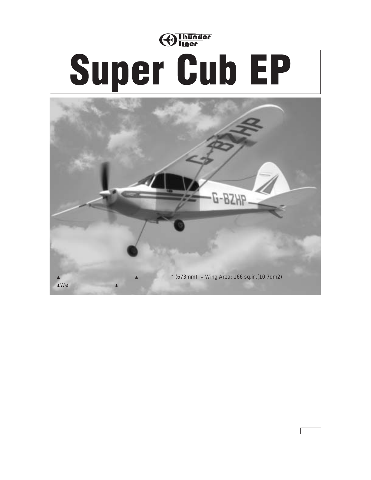
No.4315 Super Cub EP
Wing Span: 39.85"(1012mm) Length: 26.5
W.e?W.?hg
?W.YeW.Y?hg
?7U?e7U
?@1?e@1
?@@?e@@
(673mm) Wing Area: 166 sq.in.(10.7dm2)
Weight: 14oz.(400g) Motor: Super 370 Motor with 2.67:1 gearbox included
JE6645
Page 2
2
Table of Contents
Introduction
Pre-Assembly Notes ....................3
Other Items Required
..............3
Tools and Supplies Needed
.......3
Part Drawings
W2@@@@@@@@@@@@@@@?he
7Yg@?g?O)Xh
@@@@@@@@@@@@@@@@@@@,h
?J(Mg@?g?W(Yh
?7H?g@?g?.Y?h
?@?@@@@@6X@?O2@@@6X?he
?@@@@@S@@@@@@@@@)?he
W@0MeI4@Xhg
O20Me/XeI46Khf
?'@YfV)K?eS@@?he
?V4@@@@@@@@@@@0Mhf
?W(Mhg
?@6KO2@0Y?hg
I4@U
I4@?
W.e?)X?e@?hg
7He?@)?e@?hg
@?e?@H?e@?hg
?J5?eJ@f@?eO)X?h
?7H?e7@@@@@@@@@@@)?h
?@e?C(Mf@?hg
W2@@e@0Y?f@?hg
.M?@he@?e?O)Xh
?@e@@@@@@@@@@@@@@@)h
?@he@?hg
?@he@?hg
?@he@?hg
?@he@?hg
?@he@?hg
?@he@?hg
@@@@@@@@@@@@@@@@@@@?h
@? ?@H?h
@?e?@@@@@@@@@e?@he
@?e?@g@He?@he
@?e?@g@?e?@he
@?e?@@@@@@@@?e?@he
@?@@@@@@@@@@@@@@?@he
@?N@@@@@@@@@@@@5?@he
@??@he@H?@he
@??@e@@@@@@e@??@he
@??@e@@@@@@e@??@he
@??@he@??@he
@??@@@@@@@@@@@@??@he
@? ?@he
@@@@@@@@@@@@@@@@@@he
....................................4
Assembly
Wing ................................................5
Tail
................................................6
Fuselage
.......................................7
Servo
...................................8
First Flights
Balancing ........................................11
Operation Checks
...........................12
Flying
..............................................14
Repair
....................................................16
INTRODUCTION
All of us at Thunder Tiger want to thank you for choosing the Super Cup EP park flyer. This kit has been
engineered to go together quickly and easily while still providing you with great looks and exceptional flying
performance. In order to insure that your assembly process will be as smooth and uneventful as possible, we
strongly suggest that you read this assembly manual thoroughly before beginning to assemble this kit. We are
confident that you will enjoy flying this Super Cub and it will provide lots rewarding flights.
Modeling Organizations
The Super Cub EP park flyer is a serious radio-controlled model airplane and you should obtain air plane
check-out and flight training from an experience pilot to insure maximum enjoyment and programs and are very
willing to help. Also, it is recommended that you join one of the following organizations. They can help you find a
club in your area plus offer insurance programs to protect you.
Super Cup
Academy of Model Aeronautics
5151 East Memorial Dr.
Muncie, IN 47302
800-435-9262
Fax 765-741-0057
www.modelaircraft.org
Sport Flyers of America
POB 7993
Haledon, NJ 07508
800-745-3597
Fax 973-305-6686
www.modelavaiton.com
Page 3
3
PRE-ASSEMBLY NOTES
1. Please assemble your model exactly according to this
instruction manual. Do not attempt to modify or change
your Super Cub in any way as doing so may adversely
change its flying characteristics.
2. For Ready To Fly ( Super Combo) version, some
assembly steps are finished by factory craftsman. We
recommend you to read the manual to familiar the
whole plane as well and just skip the assembled step.
3. Before you begin please check entire contents of this
kit against the parts list and par ts drawings to be sure
that no parts are missing or damaged. This will also
help you to become familiar with each component.
4. If you find that any par ts are either missing or
damaged, please contact with your dealer immediately
for replacement. Note: Your dealer cannot accept kits
from return if construction has begun.
e-mail:t
hundertiger@tiger.com.tw
For customers in US please call or write to ACE Hobby
Distributors, Inc for replacement of missing or damaged
parts.
ACE Hobby Distributors, Inc.
2055 Main Street, Irvine, CA 92614
Tel: 949 833 0088
Fax: 949 833 0003
Email: service@acehobby.com
Remember we have worked ver y hard to make this model
as easy to assemble as possible while still maintaining our
high standard of quality. Your assembly of this model is
very important and will determine the final flight
capabilities of your Super Cub, so use extra care and
follow the assembly procedure exactly.
OTHER ITEMS REQUIRED
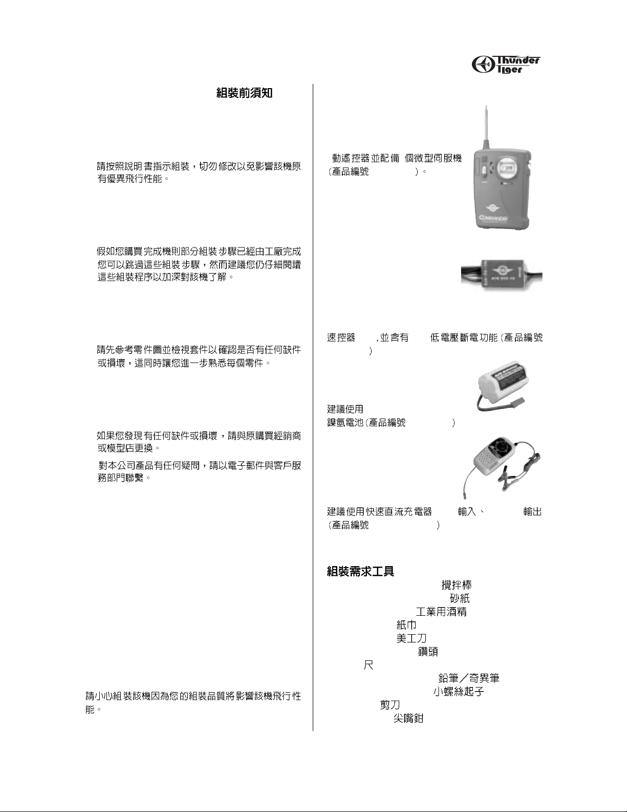
Radio: You will need at least a 3
channel radio control system with 2
micro servos for your Super Cub.
3
2
ACE 8304
ESC-10: ACE ESC-10 ( P/N
ACE8015) with BEC for controlling
the power of your Super Cub as well
as eliminating the need of a
separate radio battery. The BEC(
Battery Eliminator Circuitry) in this
controller will automatically turn off
the power to the motor when the
battery reaches a factory present
discharge level leaving about 10
minutes of flight time for the radio system.
10A BEC
ACE 8015
Battery: We recommend the use of
a 7 cell 8.4V 600mAh AAA size
NiMH battery ( P/N ACE2924)
8.4V 600mAh AAA size
ACE 2924
Charger: You will need a quick
charger to charger your power
battery. We recommend our
economical DC Quick Filed Charger
(P/N ACE2908).
12V 900mAh
ACE 2604AC/B
TOOLS AND SUPPLIES NEEDED
Mixing Stick for Epoxy
Medium Grit Sandpaper
Rubbing Alcohol
Paper Towel
Hobby Knife
1/16” drill 1.5mm
Ruler
Pen, Pencil or Marker
Small Screw Drivers
Scissors
Nose Pliers
Page 4
4
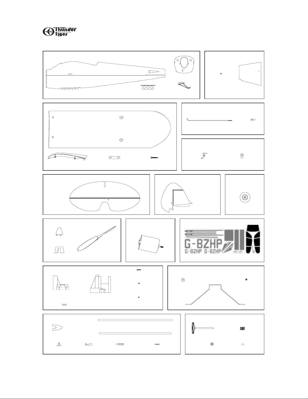
PART DRAWINGS
Open the box and check that you have all the parts as shown below. If anything is missing please contact your dealer
AS6303 Fuselage
Fuselage (1)
Landing Gear Retainer (1)
AS6304 Main Wing
Main Wing ( L/1, R/1)
Wing Center Cover (1) Wing Joiner (2) 3x25mm Wood Screw (1)
AS6305
Horizontal Tail
Horizontal T ail/Elevator (1)
Firewall (1)
Skid (1)
AS6308 Pushrod
AS6312 Snap on Control Horn
ControlHorn (2)
AS6306 Vertical Tail
Vertical Tail/Rudder (1)
AS6309 Cowling
2x8mm
Self-Tapping Screw (2)
Pushrod (2) Clevis (2)
Cowling (1)
Locking Plate (2)
No.3251
Rubber Wheel
AS6315 Propeller Set
Nose Cone (1)
Spinner (1)
AS6313 Motor Mount
Front Motor Mount (1)
Rear Motor Mount (1)
Bushing (2)
AS6307 Wing Strut
Strut Joint (2)
Hook (4)Hook Joint (6)
Propeller (1)
AS6314
370 Super Motor
Self-Tapping Screw (2)
Self-Tapping Screw (3)
Machine Screw (2)
Tube (L/2)
Tube (S/2)
Clevis (2)
370 Super Motor (1)
3x20
2.6x10
3x5mm
Threaded Wire (2)
AS6311 Decal
Decal A (1)
AS6310 Landing Gear
Wheel Collar (2)
Landing Gear (1)
AS6316 Gear Shaft Set
Main Gear/Shaft (1)
M3 Nut (2)
Wheel (2)
Decal B (1)
3x3mm
Set Screw (2)
Pinion Drive Gear (1)
Spacer (1)
Page 5
5
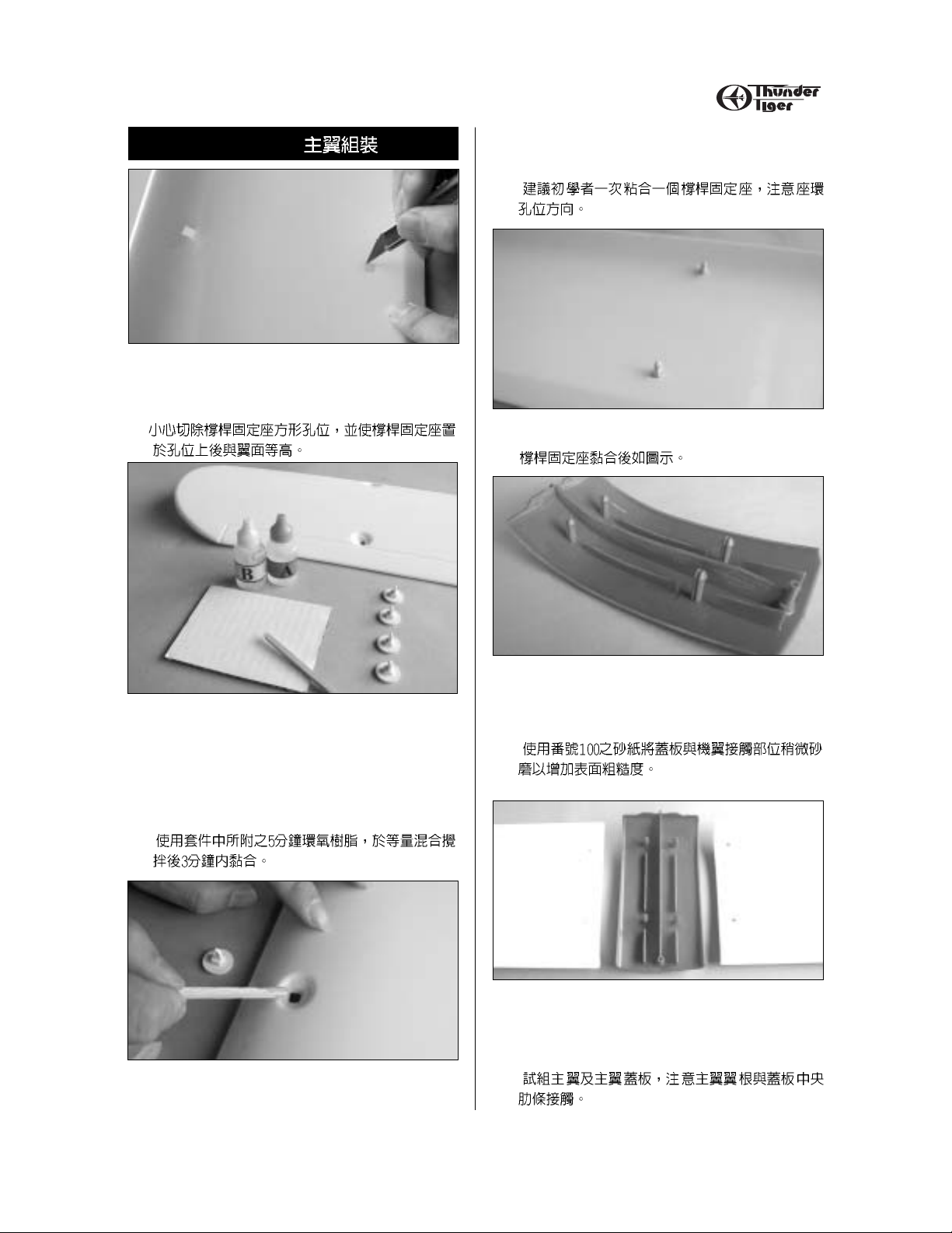
ASSEMBLY / WING
1. Carefully trim the strut mount hole in square then
trail fit the strut mount in the hole. Make sure the
strut mount is level with the wing surface.
2. Mix the furnished 5-min Epoxy to glue the strut
mount. Hint: Apply equal volume of cement in
bottle A and B on a cardboard then fully mix
them with a small stick. Note: This 5-min Epoxy
allows working time is only 3 minutes after
mixing.
3. For novice, we would recommend to epoxy one
strut mount at one time. Note the orientation
(see next step) of strut mount and make sure it is
level with the wing surface.
4. The finished strut mounts are shown.
5. Locate the wing center cover, use 100 gr it sand
paper( not furnished) slightly sand the contact
area of center wing cover.
6. Trail fit the wing halves on center wing cover.
Make sure the wing root contact the center wing
cover rib.
Wing Assembly
Page 6
6
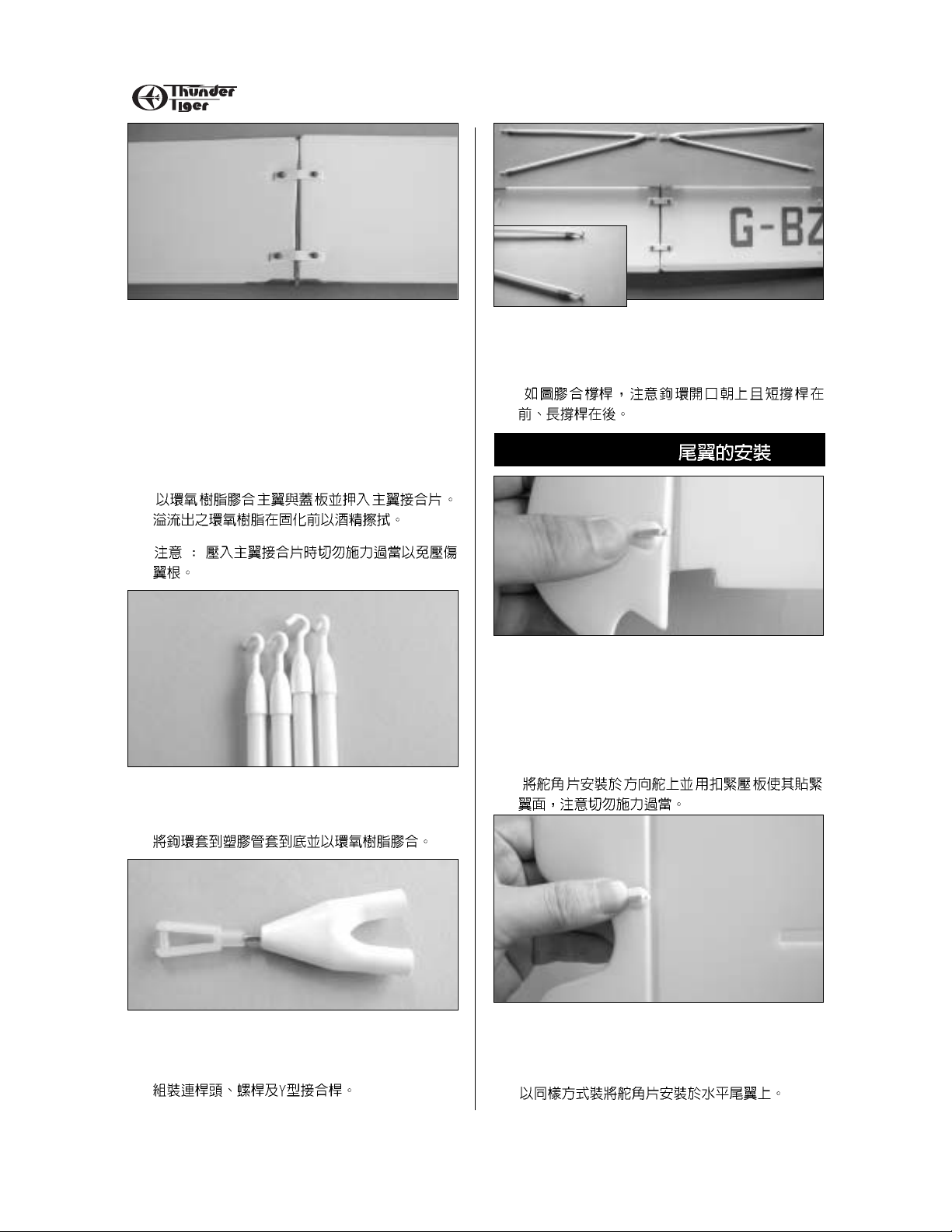
ASSEMBLY / TAILS
7. Apply 5-Min epoxy at the contact area then
place the two wing halves again and snap on the
wing joiners.
Note: Never push too hard to snap on the joiners
or may damage the wing.
Hint: Wipe off any excess epoxy with Rubbing
alcohol before it cured.
8. Locate the hooks and plastic tubs then glue the
hooks onto one end of the tubs all the way in.
9. Locate the clevises, threaded wires and Y strut
joiners. Assemble them as shown.
10. Glue the struts to the Y joiner( one long, one
short). Note the orientation of hook opening and
the upper tube is shorter as photo shown.
11. Locate the control horn and locking plate then
“Push-N-Lock” the control horn in place as
shown. Note: Do not push too hard but gently all
the way in so the control horn contacts the
surface of rudder at both sides and secured in
place firmly.
12. Do the same way on the elevator. Make sure
you are in correct orientation before installing the
locking plate.
Tails Installation
Page 7

7
ASSEMBLY / FUSELAGE
13. Trail fit the horizontal tail and vertical tail in the
fuselage, epoxy the them in place when satisfied.
Make sure they are perpendicular to each other.
14. Trial fit the plastic firewall on the front of
fuselage. Apply Epoxy at the rim of front fuselage
then glue the firewall in place.
15. Epoxy the skid in place as shown.
16. Epoxy two wing strut mounts at the bottom of
fuselage. Note the orientation of the mounts.
17. Inser t the landing gear in the fuselage then
“Push-N-Lock” the landing gear retainer.
18. Use furnished Allen Wrench to secure the
collar in place with 3x3mm set screws. Make
sure the wheel rotates freely.
Fuselage
Page 8

8
SERVO, ESC,RX & BATTERY INSTALLATION
19. Locate the EDS (electric drive system) and
remove the spinner and nuts. Note: Remove the
nose cone by rotating it counter-clockwise about
1/4 turn.
1/4
20. Secure the EDS with fur nished two 3x20 selftapping screw. Thread the Controller motor wire
through the firewall from inside of fuselage then
connect to the motor wire firmly. You may apply
a piece of tape to prevent from it loose. Next
thread the wire back to fuselage.
3x20mm
21. Drill 1/16” hole on the molded dot of the cowling.
1.5mm
22. Apply cowl decals first then secure the cowl in
place with two 2 x 8 mm wood screws.
2x8mm
23. Apply thin double side tape on the micro
servos as shown.
24. Remove a foam spacer from the servo well.
Glue the micro servo to the wall of servo well.
Servo, ESC, RX & Battery Installation
Page 9
9
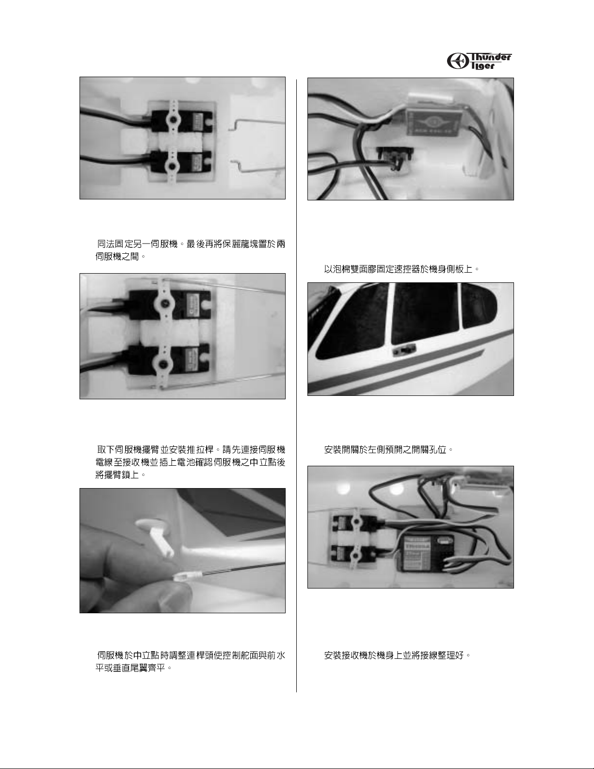
SERVO, ESC,RX & BATTERY INSTALLATION
25. Use the same way to install the other servo.
Insert the spacer between two servos.
26. Connect the pushrods to the servo horn when
servos are in neutral position.
27. Adjust the small clevises and make sure all the
control surfaces are level.
28. Connect the motor wire, next attach the
controller( ESC-10 Shown) on the wall by using
the double side foam tape. Next, install the
controller switch.
29. There is a precut slot, then use switch plate as
template to drill 2mm holes. Secure the switch
with as illustrated.
30. Connect all servo wires and controller wire.
Normally the controller wire plug into the channel
3rd ( throttle). The Servo wire plug into channel
1(Aileron) and channel 2(Elevator).
Page 10
10
SERVO, ESC,RX & BATTERY INSTALLATION
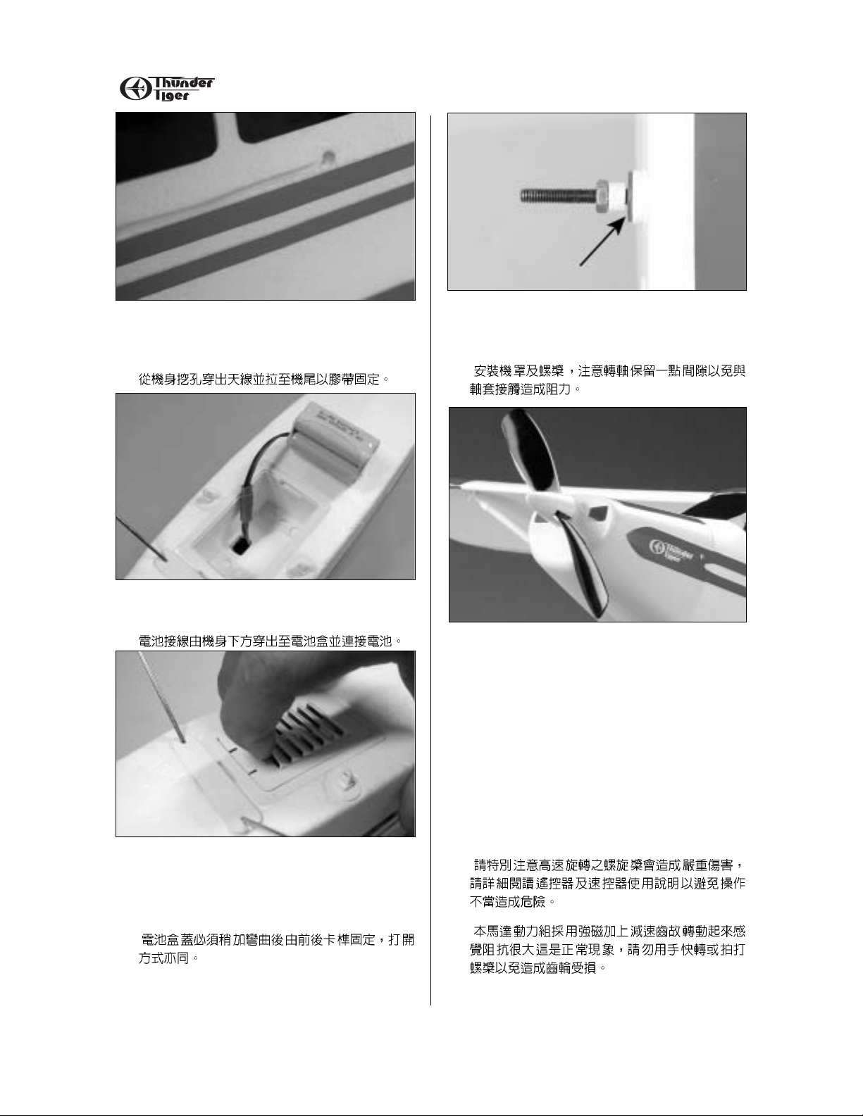
31. Drill a small hole on the fuselage at right side
then thread the antenna through the fuselage.
Route the antenna to the tail and tape it in place.
32. Connect the wire to controller and place the
battery in the battery case.
33. You will have to bow the cover plate to close or
pry with finger to remove the cover plate. Note
the opening is forward to the nose for battery
cooling.
34. Make sure the shaft is a little bit free play when
you pull and push. If it is too tight then loose the
nut for more space.
35. Next install the propeller and spinner, always
take great care on the motor and swinging
propeller as it is dangerous and may cause
serious injury, if you are a beginner we
recommend you read the manual of radio and
speed controller thoroughly to understand how to
set up and control the motor.
Note: Normally the propeller is hard to rotate as
the geared 370 motor comes with super powerful
magnets. Never rotate the propeller improperly
as it may hurt the gears.
Page 11

11
BALANCE
36. Install the main wing, note there is a pin at front
center cover which you have to inser t it into a
hole on the bulkhead in the fuselage.
Secure the wing with a 3x35 mm wood screw.
Note: The mounting plate is underneath the wing
mount area, never push hard when securing the
screw.
3x35 mm
37. Hook up the struts as illustrated.
38. Snap on the clevis to the strut mount. Adjust
the clevis if necessary.
39. Apply all decals on the plane. Congratulations!
Now you are ready to fly.
Balance
If nose drops, tape a penny to
bottom fuselage at tail end.
If tail drops, tape a penny to
inside of cowl.
5
90˚
A
A=A'
A'
2" (5cm)
Level
C.G.
C.G.
Level
Page 12
12
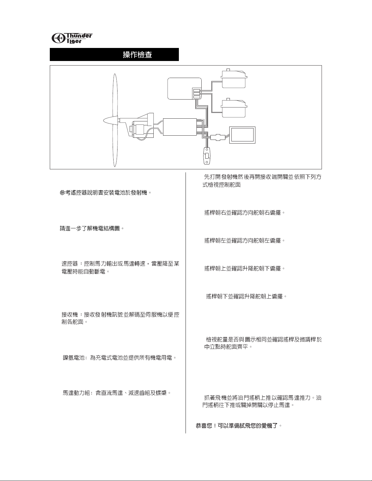
OPERATION CHECK
Operation Check
1. Install eight AA batteries in the transmitter,
referring to the radio system’s instruction manual.
2. Review the illustration to become familiar with
your airborne radio components. Following are
description of these components:
❚ ESC: This device controls power to the motor
unit. It will cut-off the battery’s voltage when it
starts to drop.
❚ Receiver: Receives the radio commands from
the transmitter and sends them to the servos
which converts the command to motion which, in
turn, moves the rudder or elevator.
❚ NiMH Batter y: Rechargeable battery pack that
provides power to the motor unit and the radio
system.
❚ Motor Unit: Contains a DC electric motor, a
gear drive, and a propeller that provides the
thrust for the airplane.
3. Turn the transmitter on and then the receiver and
refer to illustrations
( Always turn transmitter on first then the receiver
and turn receiver off first then the transmitter )
❚ Move the stick right and make sure rudder
moves to the right.
❚ Move the stick left and make sure rudder
moves left.
❚ Move the stick upward and make sure the
elevator moves down.
❚ Move the stick downward and make sure the
elevator moves up.
❚ Also check for the proper amount of throw and
make sure the rudder and elevator are in neutral
when the stick and the trim levers are in the
center.
4. Hang on the airplane and throttle up the stick.
The motor unit should come on. Make sure the
propeller is trying to pull the airplane forward.
Throttle down or turn off the switch to stop the
motor.
You are now ready to go flying!
RECEIVER
ELEVATOR SERVO
Motor
ESC-10
MOTOR UNIT
ACE
Batt
Rx
Sw
SWITCH
0N
OFF
RUDDER SERVO
BATTERY
Page 13
13
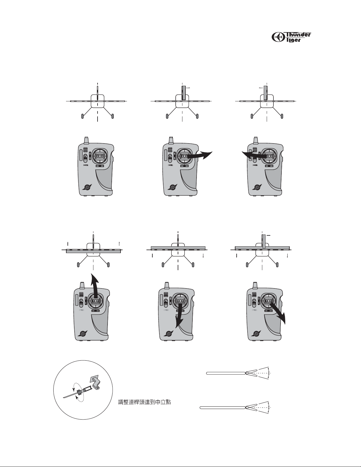
CHECK THE RADIO
Set the trim in neutral position.
Set the sticks in neutral position
Check the position of rudder and
elevator (if these are in neutral).
Move the stick to the right.
Move the stick to the left.
Move the stick up. Move the stick down. Move the stick down and right.
RIGHT AND UPUPDOWN
LEFT TURNRIGHT TURNNEUTRAL
THE DIRECTION OF MOVEMENT (RUDDER AND ELEVATOR)
To adjust neutral, unsnap the
clevis from
the horn and screw in or out
Neutral
app. 10mm
Rudder
Elevator
app. 10mm
Neutral
app. 5mm
app. 5mm
ࢫ௷ࡗ5mm
Ш௷ࡗ10mm
Page 14

14
FLYING
Flying
You should have a flight instructor to teach you how
to fly the Super Cub. Like a real airplane, you must
have an understanding of how to fly the model
before launch, or you will probably not be successful.
Check at your hobby shop or call the AMA (in the
front of this book) for flying clubs in your area.
➀ Pre-Flight Checklist
❚ Choose a calm day for your first flights. Never fly in
winds over 10 mph. Also, choose an open field
with no obstacles or people.
❚ Charge the receiver battery.
❚ Make sure there are no other pilots operating on on
the same channel (frequency) as you are. If you
turn your radio on while he is flying, you will cause
him to crash.
❚ Check your radio for good range (50 ft. with the
antenna collapsed) and proper operation.
❚ 3
❚
❚
❚ 20
➁ Take-off
❚ A proper hand-launch of the airplane is necessary
for flight. It must be launched into the wind with a
firm toss. The airplane must be tossed level or
even pointed a little down. It should never be
thrown upward, or it will stall and crash.
❚ When launching the plane, make sure your fingers
are away struts. 2 inches after the struts is
recommended.
❚
❚
➂ Flight
❚ Steer very gently right and left to keep the wings
level. Let the airplane climb out gradually and
gently until it reaches a comfortable cruise altitude
at full flight speed. Always keep the aiplane
upwind of yourself and within a reasonable
distance so you can see what it is doing.
Remember, when the plane is coming toward to
you, when you move the stick to the right, the
aiplane will go to the left from your point of view.
This is the hardest thing to learn. Initially, you can
keep your body pointed in the same direction as
the airplane and look over your shoulder. That
helps.
❚ Usually, only small stick movements are required.
Try to keep your flying smooth. You can turn the
plane by bumping small amounts of rudder and
then return to neutral. Use the elevator to keep
the airplane at the desired altitude. After awhile,
coordinate your turns with the elevator; i.e., bank
the plane with a little bit of rudder, then feed in
some up elevator to maintain the turn at the same
altitude.
❚ If the plane tends to tur n one way or the other use
the trim lever on the control stick to neutralize the
flight. Same thing applies if the place wants to
climb or dive.
❚ You can expect 3-4 minutes of “power-on” flight.
You should always maintain enough altitude so
you can set up a landing approach when the autocut off device turns the motor off and you begin
the glide.
❚
❚
❚
❚ 10
❚ 4~5
➃Landing
❚ When the motor cuts-off, set up your landing
approach. Always try to land INTO THE WIND.
Keep your turns gradual and only use elevator to
maintain a gradual glide. Since the motor is off,
you can no longer climb and the plane slows
down. If you feed in too much up elevator, the
plane will stall and may crash.
❚ Just before touchdown, “flare” the plane by adding
up elevator. The plane should slow down even
more and come in for a gentle landing. Don’t add
too much elevator, too soon!
❚ Walk over to the plane and turn off the switch on
the plane, then the transmitter switch.
❚ Remove the batteries and let them cool off before
charging up again.
❚ Check over the plane to make sure nothing
loosened up or broken.strong they can even r ip a
sailplane apart, especially if the plane is flying fast
when it passes through the thermal.
❚
❚
1~2
❚
❚
Page 15

15
FLYING
Wind Direction
Straight
Correct
and level with ground
Incorrect
Wind Direction
Wind
3 ft.
Launch firmly into wind straight and
level. Do not throw upwards!
Example of a turn using
only rudder
Launch
Landing
Example of a turn using
rudder then elevator
Page 16

16
Repair
Crash damage is not covered under the warranty!
If damage occurs, use small amount of furnished 5min Epoxy to repair broken foam. Clear packing
tape will hold the parts together; leave it on patch for
added strength. Re-balance the plane after you
repaired.
IN CASE OF TROUBLE
1. If motor does not run when Throttle Stick is up,
make sure all the wires are well connected.
Check and follow the manufacturer’s manual of
controller.
2. If the radio is erratic(glitches), check that the
transmitter and receiver antennas are extended
to their full length. Make sure the transmitter
batteries are fresh. Make sure no one else is
operation on your channel(frequency) in the
immediate vicinity.
3. If the plane does not fly properly, make sure you
are being gentle with the control inputs. Make
sure the plane is balanced properly. Make sure
all the wing and tail surfaces are flat, true, and
properly attached and aligned.
If your trouble persists, call authorized dealer for
technical help.
Conclusion
To defeat the laws of gravity and take to the wing is
both challenging and thrilling. We hope you enjoy
your entry into the fascination world of R/C flight and
make it your hobby for a lifetime. Please let Thunder
Tiger be your chosen brand, no matter what
direction you progress.
 Loading...