

Page 1

1
ACE Staudacher -60 ARF Airplane (TTR4563)
Distributed in North America by Ace Hobby Distributors,Inc.• 2682 Walnut Avenue,Tustin,CA 92780
Phone:714-544-0330 • www.acehobby.com • email:service@acehobby.com
Assembly Manual
Wing Span: 1650mm 65"
Wing Area: 780 in
2
Length: 1400mm 55.2"
Weight: 3400-3600g 7.5-8 lbs
Engine: .61 2 Cycle
.91 4 Cycle
Radio: 4 Channel w/5 Servos
Specifications:
Warranty
This kit is guaranteed to be free from defects in material and workmanship at the date of purchase.
It does not cover any damage caused by use or modification. The warranty does not extend beyond the
product itself and is limited only to the original cost of the kit. By the act of building this user-assembled
kit,the user accepts all resulting lliability for damage caused by the final product. If the buyer is not
prepared to accept this liability,it can be returned new and unused to the place of purchase for a refund.
JE6441
Notice: Adult Supervision Required
This is not a toy. Assembly and flying of this product requires adult supervision.
Read through this book completely and become familiar with the assembly and f light of this airplane.
Inspect all parts for completeness and damage. If you encounter any problems,call us for help.
Staudacher S-300
Page 2

2
INTRODUCTION
PRE-ASSEMBLY NOTES
Congratulations on the purchase of one of our finest ARFs to date. This scale replica of the famous
Staudacher S-300 is as faithful in its appearance as it is in its flight characteristics. Beautifully reproduced using
balsa and ply construction. Covered in durable and easil y r epairable UltraCote®,this plane is highly visible in
the air and strikingly recognizable on the ground.
Before beginning the assembly r ead the instructions thoroughl y to give an understanding of the sequence
of steps and a general awareness of the recommended assembly procedures.
By following these instructions carefully and ref erring to the corresponding pictures,the assembly of your
model will be both enjoyable and rewarding. The result will be a well built, easy to assemble ARF model,
which you will be proud to display.
This Staudacher S-300 is designed for intermediate to advanced pilots, and this manual assumes a basic
knowledge of R/C model construction.
Before you begin,check the entire contents of your kit against the parts list and photos to make sure that
no parts are missing or damaged. This will also help you to become familiar with each component of your
plane. If you find that any of the parts are either missing or damaged,please contact Ace Hobby Distr ibutors,
Inc.,Customer Ser vice immediately for replacements.
Please read the entire manual before beginning construction.
Neither your dealer nor Ace Hobby Distributors, Inc., can accept kits for return if construction has
begun.
Trial fit each part before gluing it in place. Make sure you are using the correct part and that it fits well
before assembling. No amount of glue can make up for a poor- fitting part.
Introduction . . . . . . . . . . . . . . . . . . . . . . . . . .2
Items Needed Check List . . . . . . . . . . . . . . . .3
Kit Contents . . . . . . . . . . . . . . . . . . . . . . . . .4
Wing Assembly . . . . . . . . . . . . . . . . . . . . . .5-8
Stab,Fin Assembly . . . . . . . . . . . . . . . . . . .8-10
Engine Installation . . . . . . . . . . . . . . . . . . . . .11
Fuel Tank . . . . . . . . . . . . . . . . . . . . . . . . . . .11
Landing Gear . . . . . . . . . . . . . . . . . . . . . . . .12
Servo Installation . . . . . . . . . . . . . . . . . . . . .12
Cowl & Canopy Installation . . . . . . . . . . .13-14
Prop & Spinner . . . . . . . . . . . . . . . . . . . . . . . . .14
Control Throws . . . . . . . . . . . . . . . . . . . . . . . .14
CG,Flight Tips . . . . . . . . . . . . . . . . . . . . . . .14-15
Spare Parts
. . . . . . . . . . . . . . . . . . . . . . . . . .15
Other Accessories . . . . . . . . . . . . . . . . . . . . 15
Other Planes . . . . . . . . . . . . . . . . . . . . . . . .16
TABLE OF CONTENTS
Page 3
3
RECOMMENDED TOOLS & MATERIALS
Adhesives:
Instant setting cyanoacrylate adhesive (thin CA)
Slower setting cyanoacrylate adhesive (medium CA)
5 Minute Epoxy (fast)
20-30 Minute Epoxy (slow)
R/C 560 Canopy Glue
Zap-A-Dap-A-Goo II™
Tools:
Model knife,T-Pins,1/2”vinyl tape
Small screwdrivers,medium screwdrivers
Lexan Scissors
Steel straight edge
Long nose pliers and diagonal cutting pliers
Drill and drill bits
Sanding block
Fine felt tip pen and soft lead pencil
Straight building board
R/C System:
4 channel radio with 5 standard servos
Two 12" aileron extensions
One “Y”style extension wire
Engine:
2 cycle: .60
4 cycle: .91
Propeller (appropriate for engine type and
preferred performance)
Radio - A 4-channel radio with 5 STD servos and are
required.
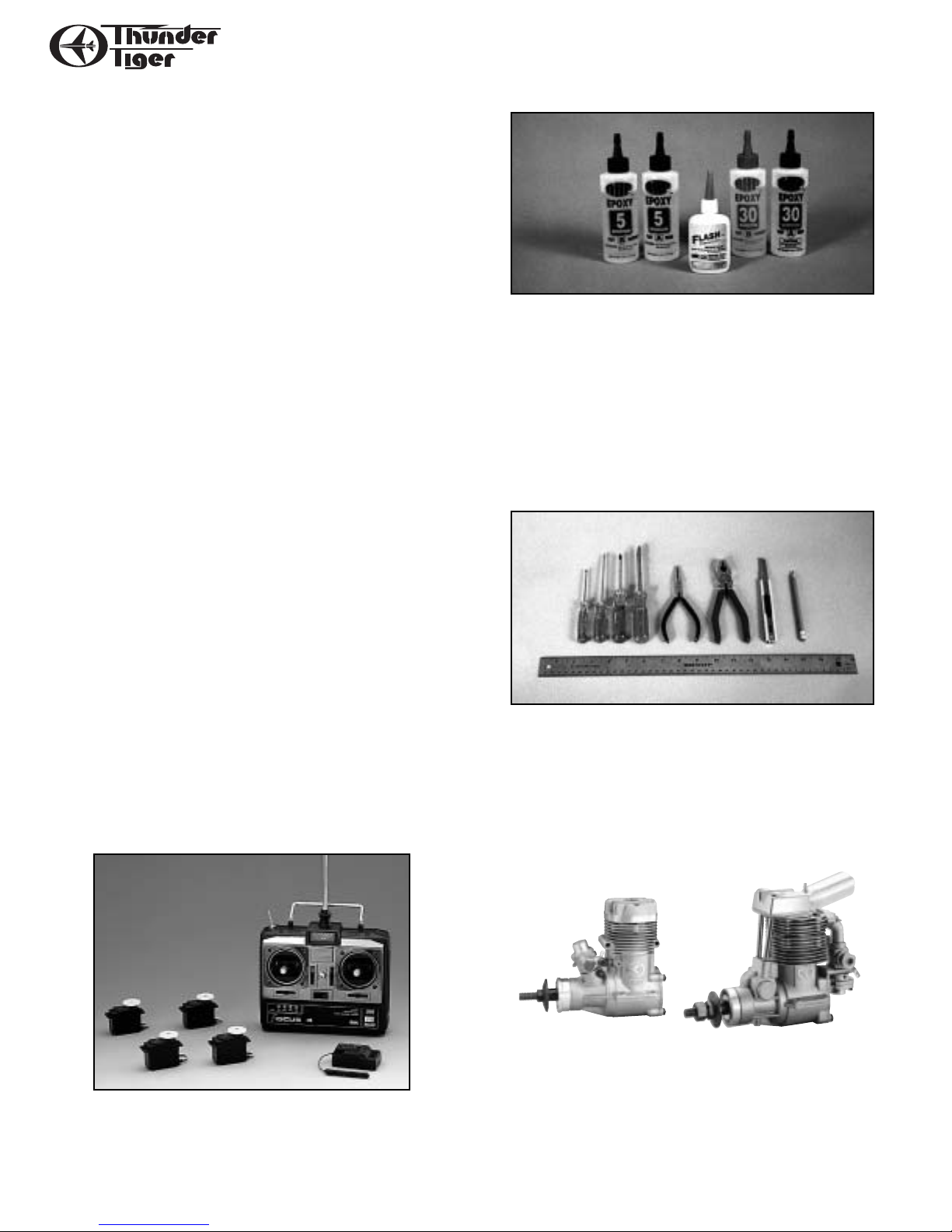
Adhesives - You will need two types of adhesives
for the Staudacher S-300 - Epoxy and Instant
(cyanoacrylate) adhesives.We recommend that you
purchase both 5-minute and 30-minute epoxy to cut
down on assembly time,but you can get by with only
30-minute epoxy if time is not important. You will
also need a small bottle of both “Thick” and “Thin”
instant CA adhesive.
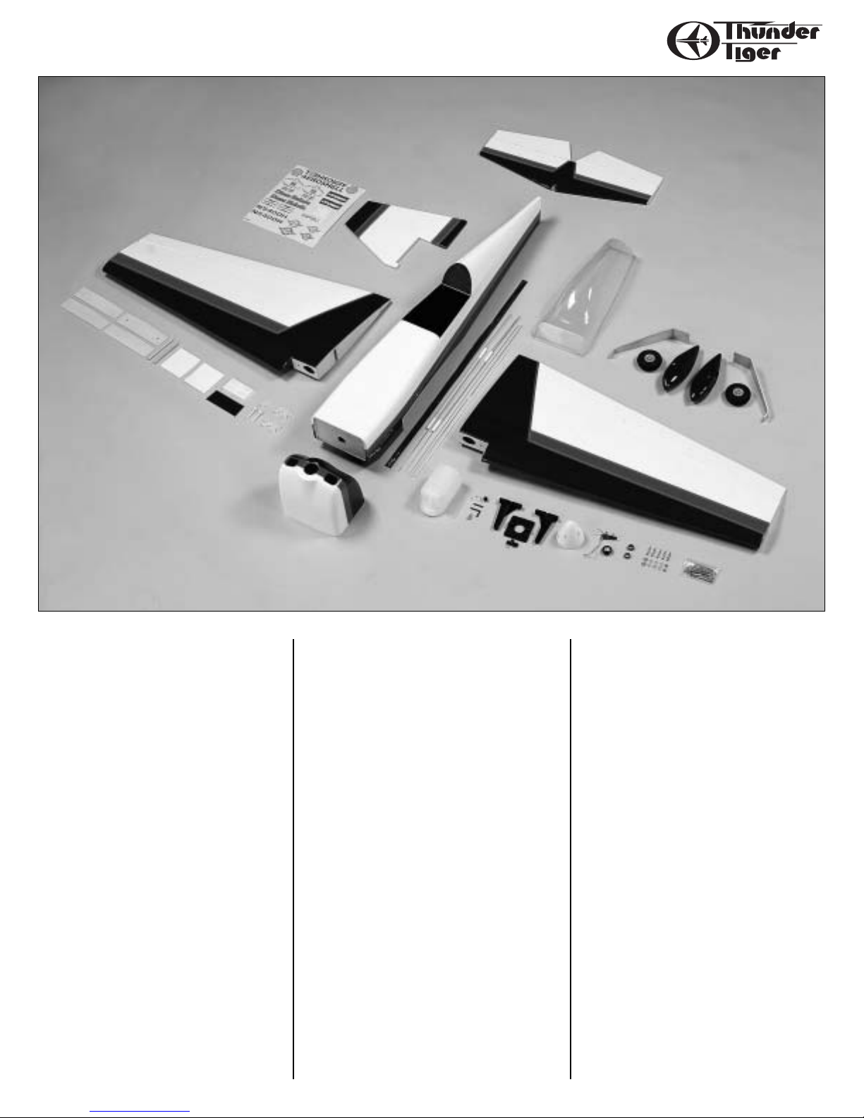
Tools - Model assembly can be much easier if the
proper tools are used. Therefore, we have included
in our checklist to the left, a complete listing of all
the tools we used to assemble our prototype models. As you will notice, many household tools can be
utilized during construction.
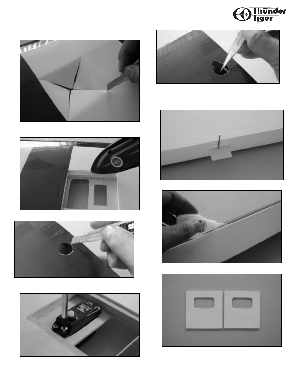
Engine - The Thunder Tiger PRO-61 & F-91S are
the ideal engines for this airplane.These quiet-running engines are easy to start, require no special
break-in periods, are very easy to maintain and will
last for years.
Page 4
4
KIT CONTENTS
Kit Contents:
Main Wing
Left Wing x 1pc
Right Wing x 1pc
Hatch Cover Plate x 2pcs
2x8mm Mounting Screw x 8pcs
Dowel x 2pcs
Dihedral Wing Joiner x 3pcs
Wing Dowel Plate x 1pc
Wing Protector x 1pc
Wing Boltx 2 pcs
Fuselage
x 1pc
Spinner
Spinner x 1pc
Backplate x 1pc
3x16mm Self-Tapping Screw x 4pcs
Pushrod
Rudder Pushrod x 1pc
Elevator Pushrod x 1pc
Aileron Pushrod x 2pcs
Throttle Pushrod x 1pc
Plastic Tube Guide x 1pc
Clevis x 5pcs
Tail Gear Set
Tail Gear x 1pc
Tail Wheel x 1pc
Collar x 1pc
Set Screw x 2pcs
3x12mm Mounting screw x 1pc
3x15mm Mounting screw x 1pc
Control Horn
Control Horn & Backplate x 5pcs
2x22mm Screw(for aileron) x 4pcs
2x15mm Screw(for rudder and
elevator) x 6pcs
EZ Connector
Connector x 1pc
M2 Nut x 1pc
3x3mm Set Screw x 1pc
Fuel T ank
Tank x 1pc
Clunk x 1pc
Nipple x 1pc
90-degree Nipple x 1pc
Fuel Stopper x 1pc
Fuel Tube x 1pc
Cap x 1pc
Engine Mount
Beam x 2pc
Backplate x 1pc
Anti-Vibration Rubber x 2pcs
4x24mm Engine Mounting Screw x 4pcs
Engine Cowl
Engine Cowl x 1pc
2.6x8mm Mounting Screw x 4 pcs
Trim Tape x 1pc
Main Landing Gear
Main Gear x 2pcs
4x15mm Mounting Wood Screw x 6pcs
4x40mm Socket Head Screw x 2 pcs
M4 Nut x 2pcs
M4 Locknut x 4pcs
M4 Washer x 8pcs(2 for wheel pants,
6 for mounting gear)
Wheel x 2pcs
Wheel Pant L/ 1pc R/ 1pc
Canopy x 1pc
CA Hingesx 18pcs
Decal x 1pc
Pushrod Fairingx 4pcs
Page 5
5
WING ASSEMBLY
I. Mount Ser vos
❐ With the wing panel upside down,locate the servo well and cut an
X from corner to corner using a hobby knife.
❐ Use a sealing iron to tack down the covering inside the servo well.
❐ With the wing rightside up, locate the servo wire exit hole and
remove covering.
❐ Attach the 12”aileron extension lead to the servo and thread the
wire through the ribs until you can see the wire connector in the first
wing panel.Secure the servo.
❐ Use Needlenose Pliers or Tweezers to take connect out. You might
wisely use a piece of clear tape to temporarily hold the servo pigtail to
the wing to prevent it from slipping back into the wing while you are
working.
❐ Remove the aileron and insert Pins into the centers of the hinges.
❐ Apply thin CA to Hinges (both sides).
❐ Locate the two Hatch Cover Plates,cut away the covering as shown.
Page 6

6
WING ASSEMBLY
❐ Secure the Hatch Cover Plates with four 2x8mm Wood Screws.
Use a pen or marker to mark the positions for the Aileron Control
Horn.Drill out the 2mm holes as shown.
❐ Attach the control horn using the 2x22mm Screw and Control Horn
Back Plate.
❐ Attached the Clevis to the threaded end and snap on to the control
horn. With the servo at neutral position mark the pushrod for Z-bend
end. Insert the Z-bend end to servo horn and secure the ser vo horn
onto the servo.
II. Join the Wing Halves
❐ Locate the three Dihedral Wing Joiners and stack them. Trial fit the
joiners in each wing panel. If needed,sand the edges lightly so that the
joiner fits in each wing smoothly.
❐ Mix some 5 minute epoxy and laminate the three Dihedral Joiners
together and clamp for 30 minutes.
❐ Mix up some more 5 minute epoxy and glue the Dihedral Joiner
into one of the wings and let it dry for 30 minutes.
Page 7

7
WING ASSEMBLY
❐ Mix up an ample amount of 30 minute epoxy and apply to the inner
ribs on each wing panel and Dihedral Joiner and make sure you have
plenty inside the wing joiner slot. Slide the wings together, tape
around the joint,and wipe of f any excess epoxy. Set aside for 1 hour.
❐ Using 5 minute epoxy, attach the Wing Dowel Plate and wing
alignment Dowels and let sit for 30 minutes.
❐ Measure the top and bottom to find center of the Wing Protector.
This will be used to center the protector on the trailing edge of the
wing panel. Place the protector on the wing panel and mark around
the three sides with a pen or marker.
❐ Remove the protector and then remove the covering material inside
the lines. Be careful not to push through the balsa; remove only the
covering.
❐ Apply a liberal amount of medium CA to the exposed wing panel
and place the Wing Protector on it,holding it until the CA sets.
❐ Iron the enclosed Trim Tape at the wing joint.
❐ Sharp the Wing Bolts as shown.
❐ Screw the Wing Bolts inversely so the sharp ends just a little high-
er than the saddle of fuselage.
Page 8

8
STAB, FIN & RUDDER
❐ Be careful install the main wing on the fuselage and not to touch
the sharp end of wing bolts. Push it to mark the points on the wing
when wing is aligned. You can see the two points at the trailing edge
of wing panel.
❐ Drill 6mm(1/4”) holes at the points. Note: The bit should be 75degree angled to the wing surface when you are drilling the hole.
III. Install the Stab, Fin & Rudder
❐ Glue the CA hinges on the stab as what you did for aileron.
❐ Cut away the covering at the rear fuselage where stab located. Also
remove the covering from the 10mm (3/8”) wide flat strip at the top
rear end of the fuselage.Carefully cut 1/2”deep on either side of the
exposed area and remove the block inside (this block should be loose
from the factory but is only there for strength during sanding and covering.)
❐ Place the stab and vertical fin in place then mark them against the
edge of fuselage.
75˚
Page 9

9
STAB, FIN & RUDDER
❐ Cut and remove the covering material about 3mm inside the stab
and fin.Be careful only cut the covering or it will hurt the structure of
the stab and fin.Using Rubbing Alcohol to remove the mark.
❐ With the main wing installed,make sure the stab and fin are parallel and perpendicular to the main wing. If not,adjust them then glue
them in place when satisfied.
❐ Install the Tail Gear by drilling 3mm(1/8”) holes for the tail gear
retaining pins.
Insert the tail gear in place then secure with 3x12mm and 3x15mm
Wood Screws.
❐ Trial fit the Rudder. Cut the slot and drill a hole for tail gear torque
rod on the rudder at the proper position as shown.
❐ Install the Rudder in place, glue the CA hinges and tail gear torque
rod.
Page 10

10
STAB, FIN & RUDDER
IV. Elevator / Rudder Servo Linkage
and Control Horns
❐ Cut away the covering of pushrod exit holes.
❐ Install the elevator pushrod,you might wisely to bend the pushrod
to Y style and two threaded ends go out the exit holes. Install the clevis on the threaded end.
❐ Place the control horn on the bottom side of the elevator and mark
screw holes with a pen or marker. Drill the holes all the way through
the elevator.
❐ Secure the control horn using 2x15mm screws provided.
❐ Install the rudder control horn. Similar procedure to elevator con-
trol assembly.
❐ Trim the Pushrod Fairing and glue them at the pushrod exits.
Page 11

11
ENGINE & FUEL TANK INSTALLATION
V. Engine Installation
❐ Locate the motor mount hardware: two beams,backplate,two antivibration rubber and four machine screws.Install the adjustable engine
mount.Remember to install anti-vibration rubber to reduce the engine
vibration. Set the engine on engine mount as shown,measure from the
firewall to the front of thrust washer at 13.5cm(5 5/16”). Mark the
engine mounting hole position on the engine mounts.
❐ Drill the engine mounting hole with 3.5mm bit(3/16”) then using
the four 4x24mm Mounting Screws to secure the engine.
❐ Drill a 3mm(1/8”) hole for throttle pushrod guide tube.Install the
pushrod tube and use a couple of drops of medium CA to hold in place
in the firewall.
❐ Install the throttle pushrod. You might need to screw off the throttle lever first then attach to Z-bend throttle pushrod end.
VI. Fuel T ank Assembly
❐ Assemble the fuel tank and install the fuel tank in fuselage.
Page 12

12
LANDING GEAR & SERVO INSTALLATION
VII. Landing Gear Assembly
❐ Run the 4 x 40mm Socket Head Bolts through the large wheels followed by a 4mm locknut. Tighten just enough so that the wheel can
turn freely.Then thread another 4mm nut and a washer then push it all
through the landing gear and wheel pant.Adjust the wheel is centered
in the wheel pant then tighten down with another 4mm locknut.
Repeat for other side.
Locate the six 4x15mm wood screws and washers to attach the main
landing gear to the fuselage.
VIII. Radio Installation
❐ Install the throttle,rudder and elevator servos.The upper one in the
photo is rudder servo,middle one is elevator servo and the bottom one
is throttle servo.
❐ With the servos are in the neutral position,use Z bend pliers to bent
the pushrod and insert the Z bend end into the servo horn. Install
throttle servo & attach the EZ Connector to the throttle servo arm
with the servo in the neutral position and the carburetor at half throttle.This will give you an excellent starting point for radio setup.
❐ Set the switch plate against the left side of the fuselage and scribe
a line inside the switch plate with an Xacto knife. Remove the switch
plate and cut through the covering and balsa. We have placed our
switch against the pink stripe.
Wrap the receiver and battery pack in foam padding and secured to
the servo tray.
Page 13

13
CO WL A TTA CHMENT
IX Cowl Attachment
❐ With the engine of your choice installed,it will be necessary to cut
holes in the cowl to accommodate cylinder heads,needle valves,glow
plug access,etc. In order to do this,create a template in the following
fashion: With engine in place,tape strips of standard paper to the fuselage over the area that will need to be removed from the cowl. Make
sure the pieces of paper are long enough to cover the cowl.
Tape the paper into place against the fuselage and carefully draw
around the necessary areas. Now using an Xacto knife, cut out the
drawn area.
❐ Now remove the engine,put the cowl into place and tape the template against the cowl.
❐ Use a marker to draw inside the template on the cowl.
❐ Trim away the mark position you drew and trial fit on the fuselage
as shown.
❐ Install the muffler and use the same way to trim the cowl.
❐ Before permanently installing the cowl,we have opted to install a
Thunder Tiger #1115 Precision Fueler Valve. Set the cowl in place.
Mark the holes for the cowl attachment screws and drill using a 1/16”
drill bit. Attach the cowl using the four 2.6x8mm Wood Screws.
Page 14

XI. Prop and Spinner
Install the prop. As we using Thunder Tiger F-91S four stroke engine,
we would recommend to us an APC 13x6~14x6.
Attach the spinner. Depending on the prop you use,you may have to
modify the spinner openings.
XII. Control Throws
These control throws are merely a starting point for your radio setup
and can be tailored to fit your flying style.
These control throws are merely a starting point for your radio setup
and can be tailored to fit your flying style.
XIII. Center of Gravity
IMPORTANT- Do not attempt to fly your model before completing
this very important section. A model that is not properly balanced will
be unstable and could cause serious damage and/or injury. Balance the
airplane right side up with your index finger tips in the center of the
main spar. Adjust the battery location or add weight as needed to
achieve level balance. Once you have everything positioned as
necessary,wrap your battery pack in 1/4" or 1/2" thick foam for protection.
The balance point is about 5” from the
leading edge, 1” out from the fuselage.
14
CANOPY INSTALLATION
❐ Since the needle valve was not long enough to extend outside the
cowl,we had to install an extension. Depending on the engine you use
this may be necessary. We made ours out of the excess wire from the
Aileron pushrod.
X. Canopy
❐ Trim the canopy by using a pair of lexan scissors.
❐ Trial fit the canopy on cockpit. When satisfied with fit, glue it in
place with Formula 560 Canopy Glue.
Page 15

15
SPARE PARTS & ACCESSORIES
XIV. Locate A Good Flying Site
Generally, the best place to f ly your model is at an AMA (Academy of
Model Aeronautics) chartered club field. Your local hobby dealer can
tell you if there is such a club in your area or write the AMA for
information. It is also a good idea to join this organization before
flying your model since they offer liability insurance that can protect
you if your model causes damage or injury to others.
Academy of Model Aeronautics
5151 East Memorial DR
Muncie, IN 47302-9252
If there is not a chartered club field in your community, you will need
to find a large area free of obstructions, and has a smooth grass or
asphalt surface to be used as a runway. For safety’s sake,it should be
located well away from houses,buildings,schools,power lines and airports.
If you will be flying within 6 miles of an airport,you should check with
the airport manager before flying your model.
XV. A Note On Batteries
The batteries are the heart of your radio system. Make sure you have
fully charged batteries! With rechargeable batteries, follow the
manufacturers instructions to make sure the batteries are fully
charged,especially the first time the radio is used.
We have used a 700mAh battery pack as the servos we installed are
only standard servos. We would recommend you use larger capacity(1000mAh) if you use high performance servos as they will draw
more current than ordinary servos.
XVI. Flying Y our Staudacher
We recommend that you take it easy on your first few flights and get
a feel for your new airplane. We test flew our Staudacher on low rates
for the first two f lights to get a feel for how it tracked and handled.
We also found that landings were smooth and uneventful on low rate.
On high rate our plane was very aerobatic,maneuvers were crisp and
clean,and incredibly responsive.
XVII. Notes
Date Date Date
Dual rate setup:
Elevator low: ________ ________ ________
Elevator high: ________ ________ ________
Aileron low: ________ ________ ________
Aileron high: ________ ________ ________
• Durable mechanism & light weight for contest use
• Super thin design for maximum versatility
• Smooth and safe locking system
• No bending necessar y, adjustable axle included for 30,40 and 60 size.
Contents:
Silicone Pick-up Tube
Straight Tank Nipple & 90° Tank Nipple
Plastic Locking Cap
Rubber Stopper
Pick-up Clunk
Features:
• Straight and 90° tank nipples are both included for ease of installation.
• Extended lip design protects fuel line from being pinched against
firewall.
• Molded-in pull tab at rear of tank allows easy tank removal.
Drilling exact holes in your engine mount plus properly locating
the prop shaft/thrust washer for positioning the spinner ring is always a
hassle, until now.
Thunder Tiger’s new Engine Mounting Guides make installation of
our most popular engines a snap;more importantly, you can leave your
brand new engine in the box and not expose it to sawdust, drill shavings, glue, and paint.
Superlite Retracts
ITEM NO DESCRIPTION
TTR3005 Retract,.10 Size
TTR3006 Retract,.30 Size
TTR3007 Retract,.40 Size
TTR3008 Retract,.60 Size
Fuel T ank Sizes
ITEM NO. DESCRIPTION
TTR3271 2.5oz.(75cc)
TTR3272 24oz.(720cc)
TTR3273 32oz.(960cc)
Engine Mounting
Guides
ITEM NO. DESCRIPTION
TTRPN0197 Guide, GP-07
TTRPN0198 Guide, GP-42
TTRPN0199 Guide, PRO-40/46
TTRPN0200 Guide, PRO-25/36
TTRPN0201 Guide, PRO-61
XVIII. Spare Part
#AS6174 FRP Cowl
#AS6175 FRP WHEEL PARTS
#AS6176 MAIN LANDING GEAR SET
#AS6177 CANOPY
Look at Thunder Tiger Accessories
Page 16

16
• Skillfully built from balsa/ply and covered
with UltraCote
• Sleek lines and tapered wing provides
clean,smooth performance
• Set-up for fixed gear or optional retracts
60 ARF
ACE4559
If you are looking for a perfect sport
airplane, you can't go wrong with a Cloud
Dancer 60. Designed by the late Fred
Reese,the Cloud Dancer 60 incorporates a
strong lightweight frame that provides
instant acceleration and nimble responsiveness for very impressive and truly
enjoyable perfomance.
Cloud Dancer sports a double-tapered
wing, a unique diamond-shaped tail group,
wide-stance landing gear and wheel pants,
and sleek fuselage with bubble canopy.
All of which results in a truly handsome
airplane you can be proud of. Install the
optional retractable landing gear,and watch
the Cloud Dancer transform into the next
level of awesome performance and good
looks.
The Cloud Dancer 60 comes Almost-
Ready-To-Fly, completely built from
balsa/ply and skillfully covered with
UltraCote®.
Wild blue yonder” takes on
a whole new meaning when you
are pushing either of these ARF Giles 202
through the sky. Crisp aerobatics are what
these replicas of the world famous airplane
is all about.
This Almost-Ready-To-Fly airplanes is
meticulously built from balsa/ply and covered with UltraCote. A few hours of final
assembly plus radio and engine installation
and you are ready to head for the tarmac and
wave to the crowd after a successful airshow
performance.
• Skilled craftsmen completely build this
model from top quality balsa and plywood.
•Covered in Ultracote,the G-202 color
scheme is bright,tough,and repairable.
•A flawlessly painted fiberglass cowl,
blow molded wheel pants, and bottom
wing cover are furnished.
• Quality accessories include pilot figure
and instrument panel.The 1.40 includes
scale tail-wheel assembly, flexible engine
mount,and heavy duty linkage.
ACE4559 Cloud Dancer 60
Wing Span: 72”
Wing Area: 840in2
Length: 57”
Weight: 6-7 lbs.
Engine: .61 2 cycle
.91 4 cycle
Radio: 4~5 channel
140
A R F
G-202
GILES
TTR4550 G-202 140
Wing Span: 70”
Wing Area: 1022in2
Length: 70”
Weight: 10-10.5 lbs.
Engine: 1.08-1.6 2cycle
1.2-1.8 4cycle
Radio: 4 channel
w/6 Servos
 Loading...