

Thunder Tiger SPARROWHAWK XB 4WD Maintenance Manual
Maintenance Manual & Parts Catalogue
The contents are subject to change without prior notice due to product improvements and specificatrion changes.
Introduction
前言
Thank you for purchasing this Thunder Tiger product. This manual contains the steps and instructions required to assemble
your car. Please read this manual completely before attempting to start maintenance. Follow the directions in this manual closely
to reduce problems during operation. We offer online help on our www.acehobby.com or www.thundertiger.com and forums
and our product specialists are ready to take your call if you have any technical questions. Have fun and enjoy the exciting world
of R/C.
感謝您購買雷虎科技 SPARROWHAWK XB 電動越野車。雷虎科技一向以提供最高品質的產品及服務作為持續努力的目標,並藉由參與競賽及重
覆測試產品,不斷累積經驗,進而提昇設計及製造品質,期望能呈現給您最頂級之工藝產品。本使用說明書包含了組裝及維修本產品前所需注意
的重要事項,建議您在開始組裝及維修本產品之前,能詳閱此說明書,並熟悉本產品之組裝步驟及維修程序。若是您在產品的使用上有任何的疑
問,歡迎多加利用我們所提供的24小時諮詢留言版或洽詢雷虎科技授權經銷商。雷虎科技的全球英文網址為www.thundertiger.com,我們將竭誠
為您服務!
維修說明書及零件包型錄
1/10 SCALE ELECTRIC POWERED RACING BUGGY
1:10
電動競速越野車
本套件所附之零件可能跟圖示有所差異。因產品後續之設計研發或功能不斷改善之原因,我們將保留產品規格變更權利,不再另行通知使用者。
This radio control model car is not a toy! Before beginning assembly, please read this manual thoroughly.
本產品為高性能模型非一般玩具,組裝與操作前請詳閱本產品說明書。
No.6536-F
STEP12 Steering Servo 轉向伺服機
STEP13 Installation of Motor Mount 結合馬達組
STEP14 Installation of Top Plate 結合二樓板
STEP15 Installation of Battery Pack 安裝電池
STEP16 Receiver & E.S.C 接收機與速控器
STEP17 Tire/Wheels 輪胎及輪轂
STEP18 Body Shell 車殼
SPARROWHAWK VX EXPLODED VIEW 爆炸圖檢索
SPARROWHAWK VX PART 零件表
SPARROWHAWK VX OPTION PART 改裝配件
BODY SHELLS 車殼
WHEEL & TIRE OPTION PART LIST 輪胎與輪轂
OPTIONAL ELECTRONICS 選配電子產品
1
Under Safety Precautions 安全注意事項
Please read all of the instructions and familiarize yourself with the product and its controls before operation.
1. This product is not a toy. It is a high performance model car therefore it is important to familiarize yourself with the model,
its manual, and its construction before assembly or operation. Adult supervision is necessary for children operating this
model.
2. Always keep this instruction manual on hand during assembly and for operating reference.
3. Do not use a power screwdriver to install screws into plastic parts. A power screwdriver’s high rotation speed can heat
up the screw being installed which can result in some melting of the plastic parts or stripped threads.
4. For best performance, it is important to make sure all the moving parts can move freely without binding.
5. This product, its parts, and its assembly tools can be harmful to your health. Always exercise extreme caution when
assembling and operating this product. Keep away from any high speed rotating parts during operation.
感謝您購買雷虎科技產品,在您開始操作本產品前,請詳閱本產品說明書。
1.
本產品為高性能模型產品非一般玩具,組裝與操作過程皆須由成人陪同。請詳讀此本使用說明書,避免因組裝錯誤與操作不當造成損壞。
2.
請妥善保管此說明書,對於後續維修、操控說明將可提供您協助。
3. 請勿使用電動工具旋緊自攻螺絲於塑膠零件上,可能導致塑膠零件融化或滑牙。
4.
請檢視所有活動部位零件是否不受干涉,可靈活作動,以達到車輛最佳性能。
5.
此項產品具有相當之危險性,於組裝、調整、操控上的不熟悉都可能造成自身或他人的傷害,當發生這些傷害事件時製造商是可以免除責
任的,建議您於初次使用本產品前,先行請教具有相當程度經驗同好或是專業雷虎經銷商與模型專賣店。
Index 索引
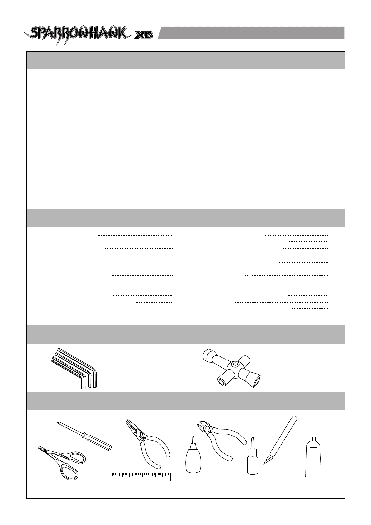
Tools Included
內附工具
Hex Wrenches
1.5 / 2.0 / 2.5 / 3.0mm
六角板手組
4-Way Cross Wrench
十字套筒
Tools Required For Assembly
組裝維修工具
Philips Screwdrivers
(L/M/S)
十字起子
Needle Nose Pliers
尖嘴鉗
Hobby Knife
模型用切割刀
Wire Cutter
斜口剪
Lexan Body Curved Scissor
車殼專用剪
Ruler
尺
Super Glue
(CA Glue)
快乾膠
Grease
潤滑油膏(黃油)
Thread Locking Adhesive
(Threadlocker)
螺絲防鬆膠
CA
Manual Format 說明書使用方式
Symbols Used Throughout The Manual 符號說明
STEP1 Rear Differential 後差速組
STEP2 Slipper Clutch 扭力控制器
STEP3 Rear Bulkhead Unit 後差速箱
STEP4 Rear Suspension 後擺臂懸吊組
STEP5 Front Bullkhead Unit 前齒輪箱
STEP6 Front Suspension 前擺臂懸吊組
STEP7 Shock Absorber 避震器組
STEP8 Steering Bellcrank 轉向曲柄組
STEP9 Installation of Rear End 結合後擺臂懸吊組
STEP10 Installation of Front End 結合前擺臂懸吊組
STEP11 Steering Servo 轉向伺服機
P.2
P.2
P.3
P.3
P.4
P.4
P.6
P.7
P.10
P.12
P.13
P.13
P.14
P.15
P.15
P.16
P.16
P.17
P.17
P.18
P.19
P.22
P.27
P.30
P.31
P.32
How to read the instruction manual?
Must be purchased separately
改裝品需另購
Apply C.A Glue
使用快乾膠黏合
Apply silicon oil
使用模型專用矽油
Assemble as many times as specified
依指示組裝所需數量
Assemble left and right side the same way
左右側組件相同
Assemble in right order
依標示順序組裝
Drill holes with the specified diameter
依標示尺寸鑽孔
Cut off shaded portion
依標示部分裁切
Ensure smooth, non-binding movement when assembling
確認組件靈活度
Pay close attention here
注意組裝步驟
Cut off excess
裁剪多餘部分
Apply threadlocker
使用螺絲防鬆膠
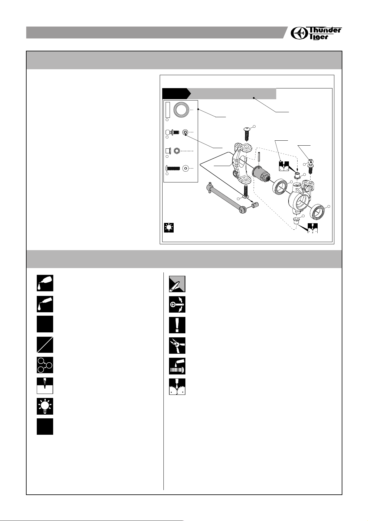
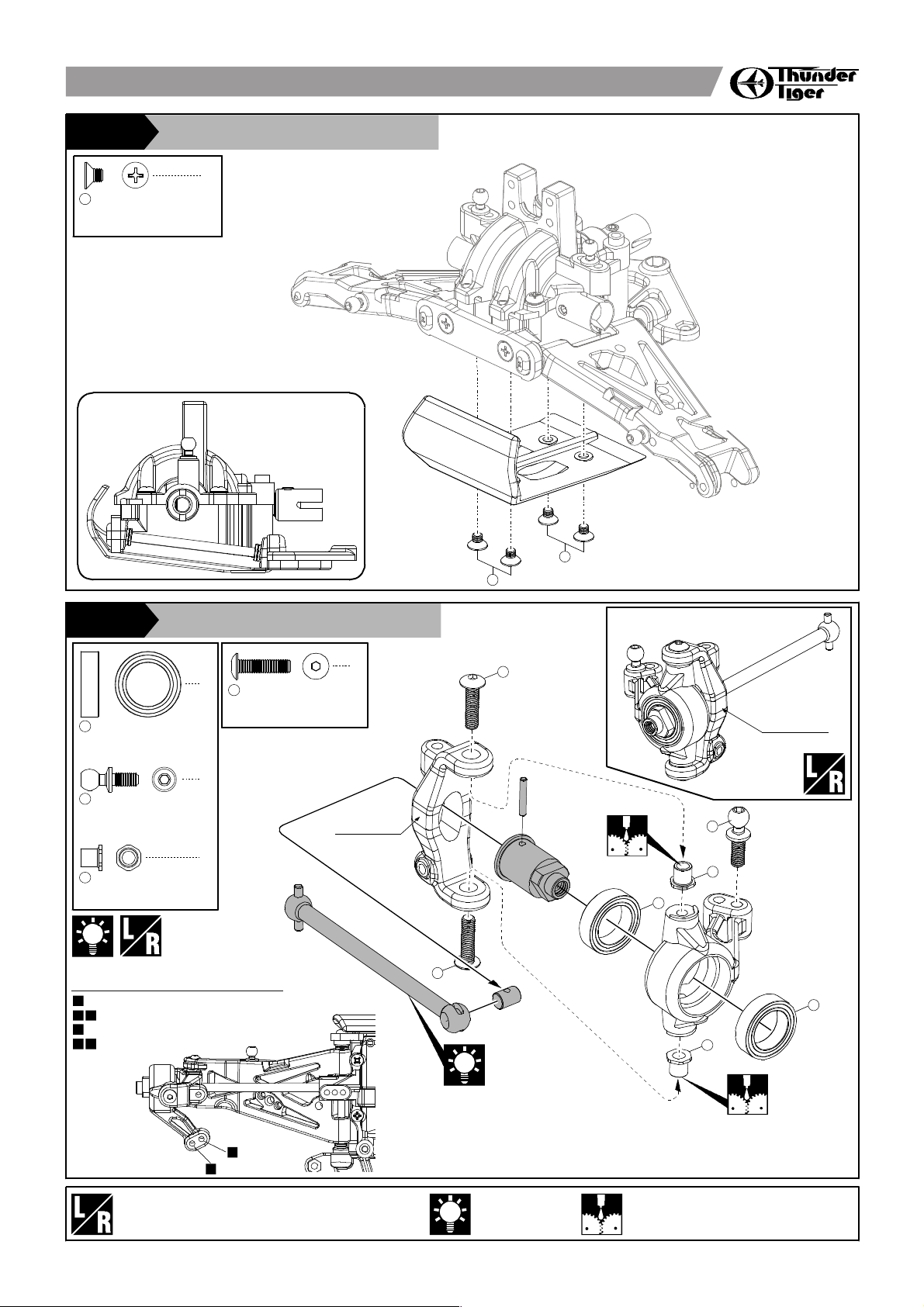
STEP4
Front Suspension 前擺臂懸吊組
6mm
Ball Stud
球頭座
10x15x4mm
Ball Bearing
軸承
3x12mm
BT Machine Screw
圓頭十字螺絲
Caster Block Bushing
C型輪座
In the chassis set, these dog bones have been assembled in one-piece unit.
原廠已組配完成
Marked "L"
標示 "L"
4
2
4
4
4
3
2
1
1
4
3
2
4
1
3
Apply grease
使用潤滑油膏(黃油)
2
Manual Format
Example 說明範例
Symbols Used Throughout The Manual
oil
C.A
x
2
L
R
1
2
3
Hint
組裝提示
x
Indicates the assembly step number and the
parts that are to be assembled.
Displays actual size drawing s, and pa rt
quantities used.
All parts, except screws, are identified by its
order numbers. When purchasing spare parts,
identify the part required and cross reference
this to the spare parts list in the end of this
maunal, which shows the purchasable spare
parts and the corresponding order numbers.
This instruction manual uses several symbols.
Pay ca r ef ul atte n t ion to them du r i n g
construction. Details are given at the bottom
of each page.
顯示組立步驟及需組立之零件部位
零件實際對照尺寸及使用數量
請比對零件形狀以及後附零件料號對照圖示找
出需求零件料號
操作說明符號可更有效協助組裝者使用此說明
書,請依說明書符號指示進行組裝步驟
A:
B:
C:
D:
A:
B:
C:
D:
說明書使用方式
符號說明
A
B
C
C
D
說明書導讀
Must be purchased separately
改裝品需另購
silicon oil
矽油
Assemble as many times
as specified
依指示組裝所需數量
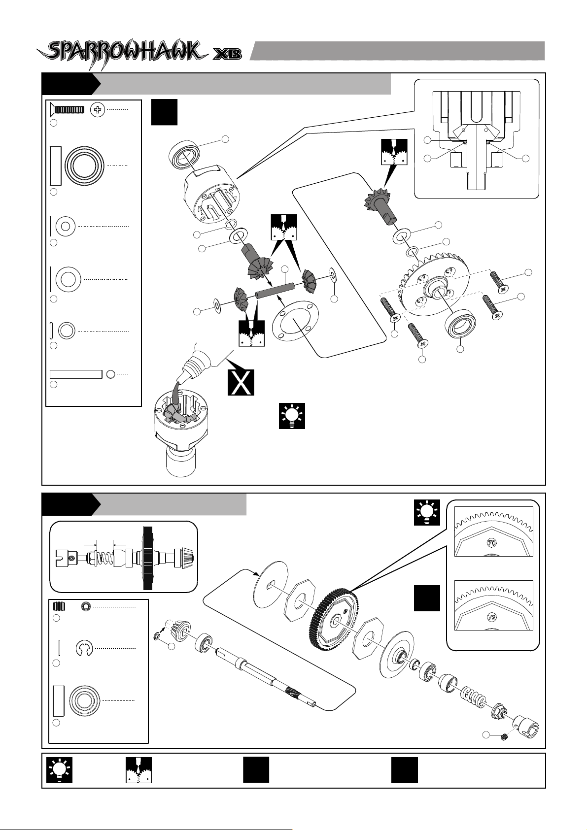
STEP2
Slipper Clutch 扭力控制器
3
STEP1
Front Differential 前差速組 / Rear Differential 後差速組
You m ay also use silicone oil to replace grease for the
differentials. Fill up to 80%. Change the viscosity of the silicone
oil according to track conditions and your driving style.
玩家可依需求選購不同番號之差速矽油來取代原廠組裝使用之
黃油。裝填時液面請勿超過差速本體上緣(約八分滿即可)。差
速矽油需另外採購。玩家可依操作習慣及操作路面情況選擇適
合濃度之矽油來調整差速反應。
Hint
組裝提示
Apply grease
使用潤滑油膏(黃油)
2
x
1
4
4
4
4
8
8x14x4mm
Ball Bearing
軸承
2
2.5x12mm
F/H Philip Machine Screw
平頭十字螺絲
1
3x5mm
Washer
墊圈
3
5x8mm
Washer
墊圈
4
4.4x0.8mm
O-Ring
O型環
5
3x19mm
Pin
銷
6
5
4
3
6
3
1
1
2
1
1
5
4
4
5 5
X
2
X
2
2
1
Standard
標準件
Optional
改裝件
x
7mm
Side View
側視圖
1
3x4mm
Set Screw
無頭內六角螺絲
1
1
2.5 mm
E-clip
E型扣環
2
2
5x11x4 mm
Ball Bearing
軸承
3
Assemble left and right
side the same way
左右側組件相同
Pay close attention here
注意組裝步驟
Apply threadlocker
使用螺絲防鬆膠
4
Rear Suspension 後擺臂懸吊組
STEP4
Apply grease
使用潤滑油膏(黃油)
Hint
組裝提示
Rear Differential Unit 後差速箱
STEP3
A B
AB
L
R
6mm(L)
Ball Stud
球頭座
1
2
4
3x12mm
BT Philip Machine Screw
圓頭十字螺絲
2
2
2
14x10.5.x0.1mm
Diff Shim
差速箱墊片
3
4x3mm
Set Screw
內六角螺絲
4
Also see P.5
另參考第5頁
A B
A B
B
B
Camber Adjustment
外傾角調整
For Ready Set Camber Linkage
For Optional Turnbuckle Linkage
Not Recommended Set Up
適用原廠固定式上臂拉桿
適用改裝可調式上臂拉桿
非原廠建議調整孔位
Adjust the backlash
with the shims.
用來調整差速器本
體與齒輪箱之間
距,減少共振。
Inner hinge Pin
擺臂軸
1
2
2
2
6mm(S)
Ball Stud
球頭座
2
3x10mm
F/H Philip Machine Screw
平頭十字螺絲
3
Roll Center Adjustment
調整滾動中心
Roll
Center
Position
滾動中心位置
Low
最低 偏低
Mid. Low
中間
(原廠 設 定 )
Mid. High
High
偏高 最高
Medium
(Factor y
Set-up)
arm
mount
bushings
擺臂軸套
Track路況Low Speed Track High Speed Track
多彎 高速路面
Always adjust the fro nt and rear bus hings at t he same time. Your car ma y not run stable if
front and reaer bushings are unbalanced.
調整時請同時更換前後擺臂軸套。不平衡的設定將增加車輛行駛的不穩定性。
1
3
4
1
2
2
3
4
Marked "。。"
標示 "。。"
3
2
1
1
2
3
Assemble as many times as specified
依指示組裝所需數量
Assemble left and right side the same way
左右側組件相同
5 6 7
Rear Suspension 後擺臂懸吊組
STEP4
4
10x15x4mm
Ball Bearing
軸承
1
6mm(L)
Ball Stud
球頭座
2
2
Rear Suspension 後擺臂懸吊組
STEP4
X
2
2
2x4mm
BT Self-Tapping Screw w/washer
圓頭十字墊圈螺絲
1
2
2.5x22mm
Outer Hinge Pin (Rear)
擺臂軸
2
X
2
1
2
Hint
組裝提示
Camber Adjustment
外傾角調整
For Ready Set Camber Linkage
For Optional Turnbuckle Linkage
適用原廠固定式上臂拉桿
適用改裝可調式上臂拉桿
A B
A B
B
B
A B
AB
1
1
2
In the chassis set, th ese dog
bones have been assembled in
one-piece unit.
原廠組配已完成
Marked "B-CM"
標示 "B-CM"
Hint
組裝提示
Rear Suspension 後擺臂懸吊組
STEP4
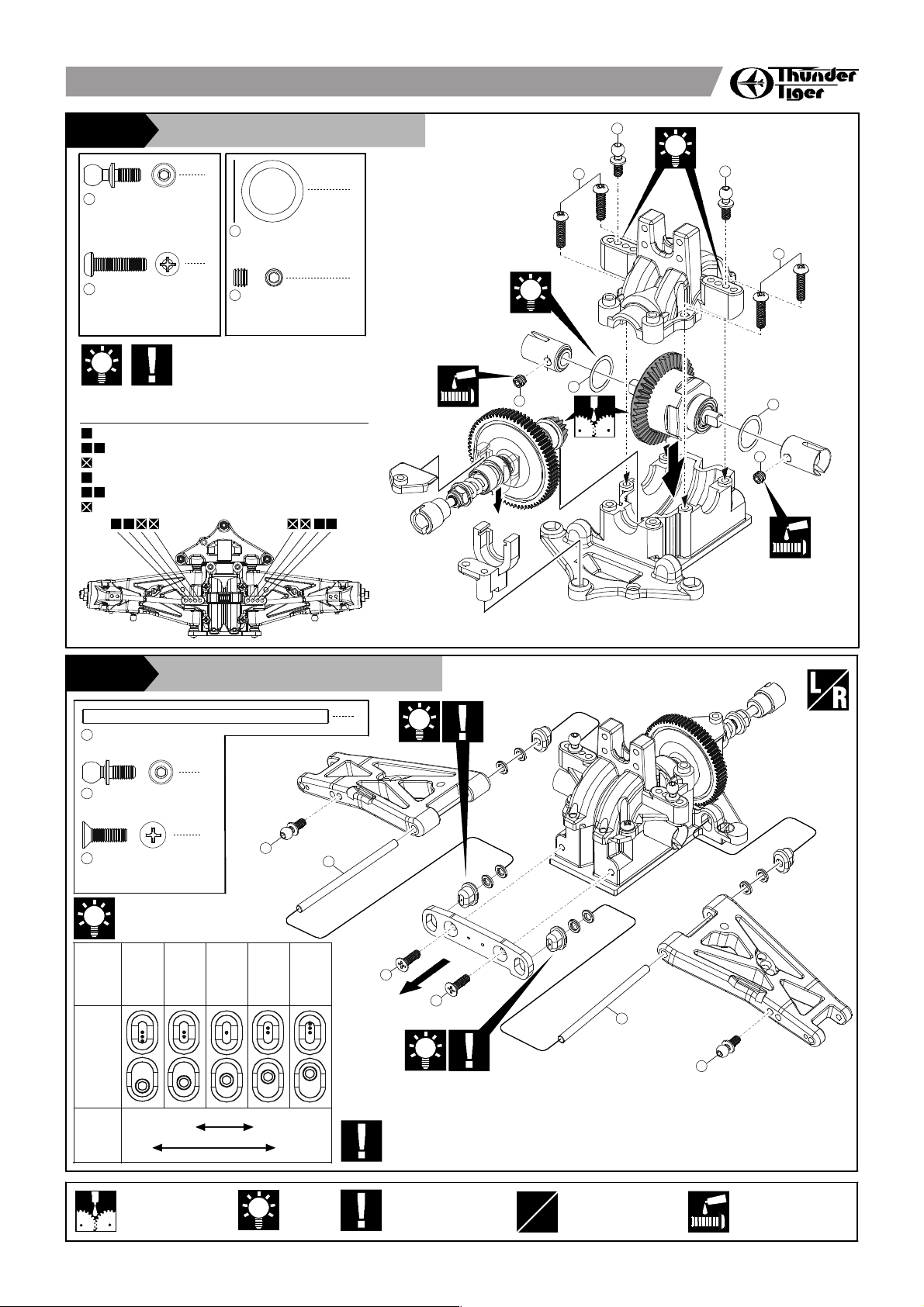
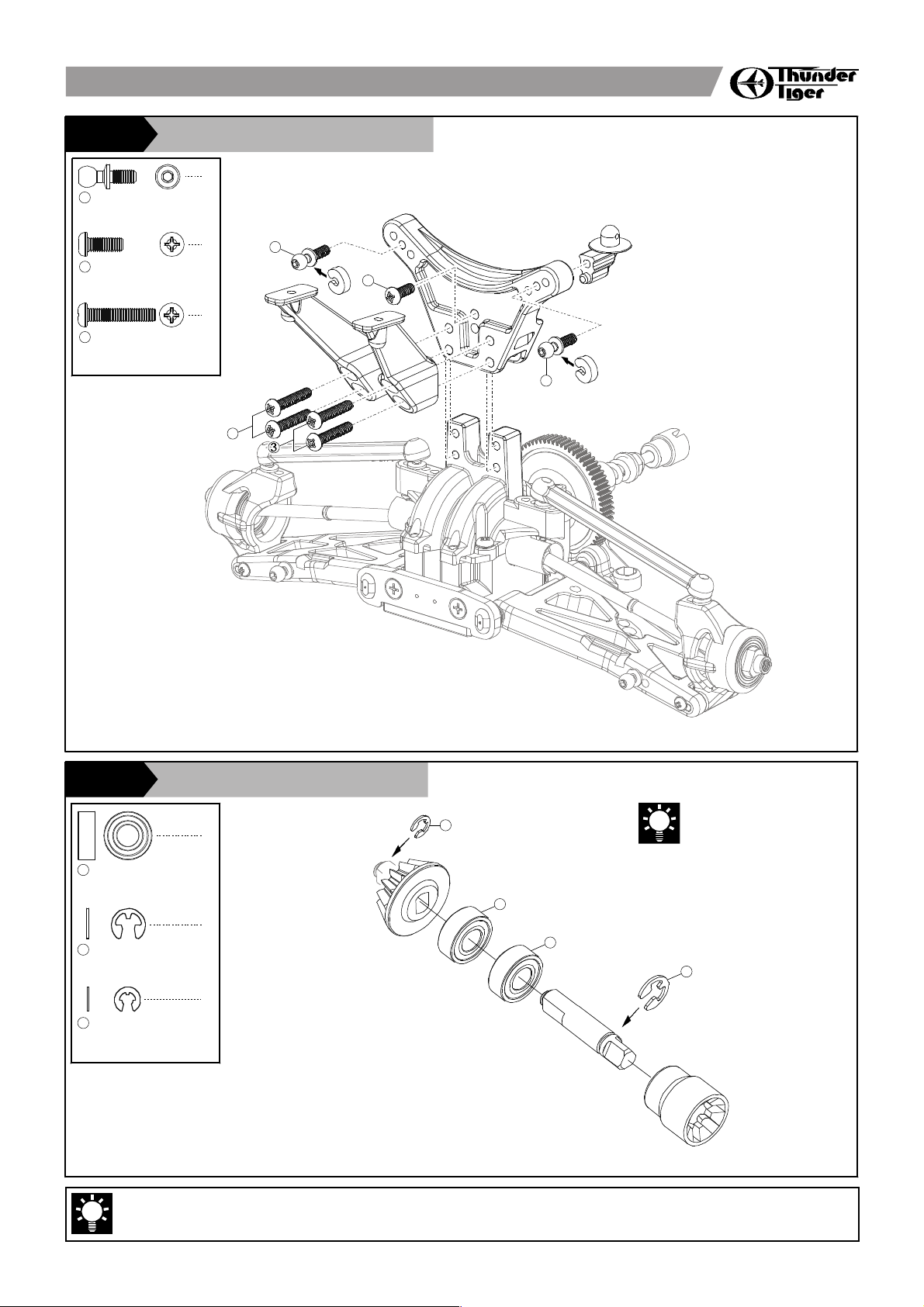
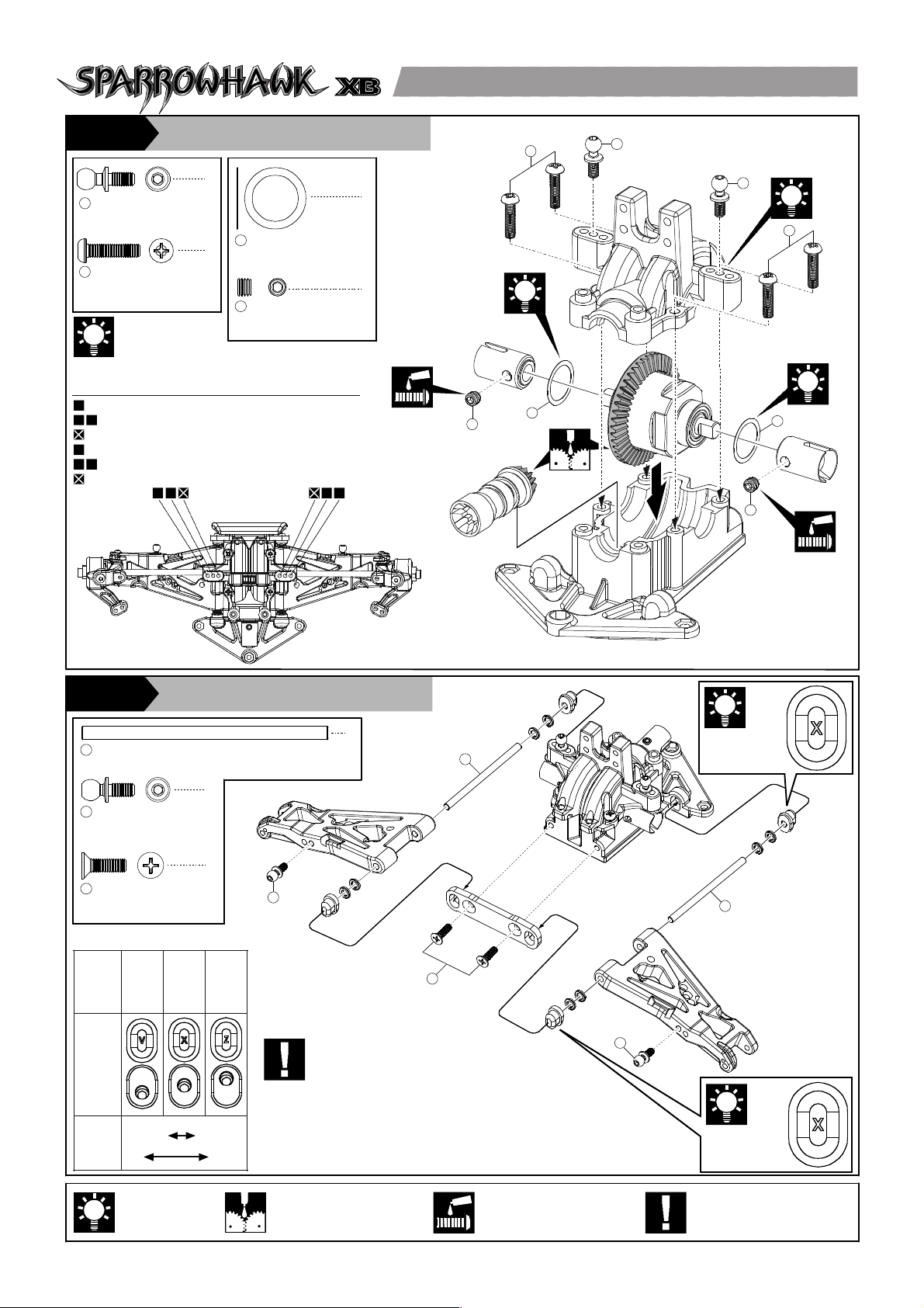
Front Differential Unit 前差速箱
STEP5
6 mm(L)
Ball Stud (PD9104)
球頭座
1
2
4
3x8 mm
BT Philip Machine Screw
圓頭十字螺絲
2
4
3x16 mm
BT Philip Machine Screw
圓頭十字螺絲
3
Leave one unit of drive axle for
next step.
將剩餘組件留待接下步驟組裝
2
5x11x4 mm
Ball Bearing
軸承
1
4 mm
E-clip
E型扣環
2
1
1
2.5 mm
E-clip
E型扣環
3
3
1
2
1
3
1
1
2
〈Rear Shock Tower〉
〈後避震器支架〉
Pay close attention here
注意組裝步驟
Apply threadlocker
使用螺絲防鬆膠
A B AB
Front Differential Unit 前差速箱
STEP5
6mm(L)
Ball Stud
球頭座
1
2
4
3x12mm
BT Philip Machine Screw
圓頭十字螺絲
2
2
2
14x10.5.x0.1mm
Diff Shim
差速箱墊片
3
4x3mm
Set Screw
內六角螺絲
4
A B
A B
B
B
Camber Adjustment
外傾角調整
For Ready Set Camber Linkage
For Optional Turnbuckle Linkage
Not Recommended Set Up
適用原廠固定式上臂拉桿
適用改裝可調式上臂拉桿
非原廠建議調整孔位
Adjust the backlash
with the shims.
用來調整差速器本
體與齒輪箱之間
距,減少共振。
Always adjust the fro nt a nd rear bush ings
at th e same time. Your car may not run
stab le if fr on t and reaer bushi ng s ar e
unbal anced.
調整時請同時更換前後擺臂軸套。不平衡的
設定將增加車輛行駛的不穩定性。
Roll
Center
Position
滾動中心位置
Low
最低
中間
(原廠 設 定 )
High
最高
Medium
(Factor y
Set-up)
arm
mount
bushings
擺臂軸套
Track
路況
Low Speed
Track
High Speed
Track
多彎 高速路面
Factory Set-up
原廠設定
Factory Set-up
原廠設定
Apply grease
使用潤滑油膏(黃油)
Hint
組裝提示
Inner hinge Pin
擺臂軸
1
2
2
6mm(S)
Ball Stud
球頭座
2
3x10mm
F/H Philip Machine Screw
平頭十字螺絲
3
2
2
1
1
2
4
3
3
4
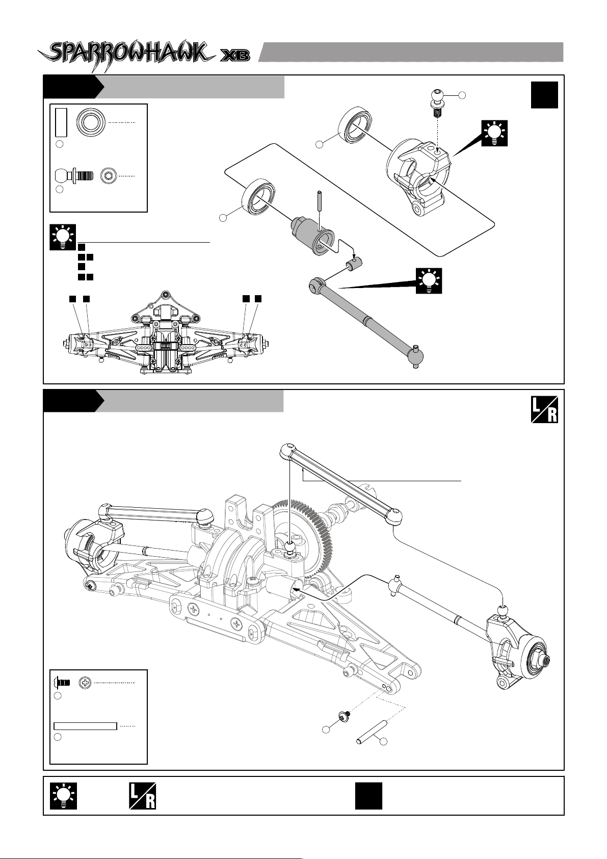
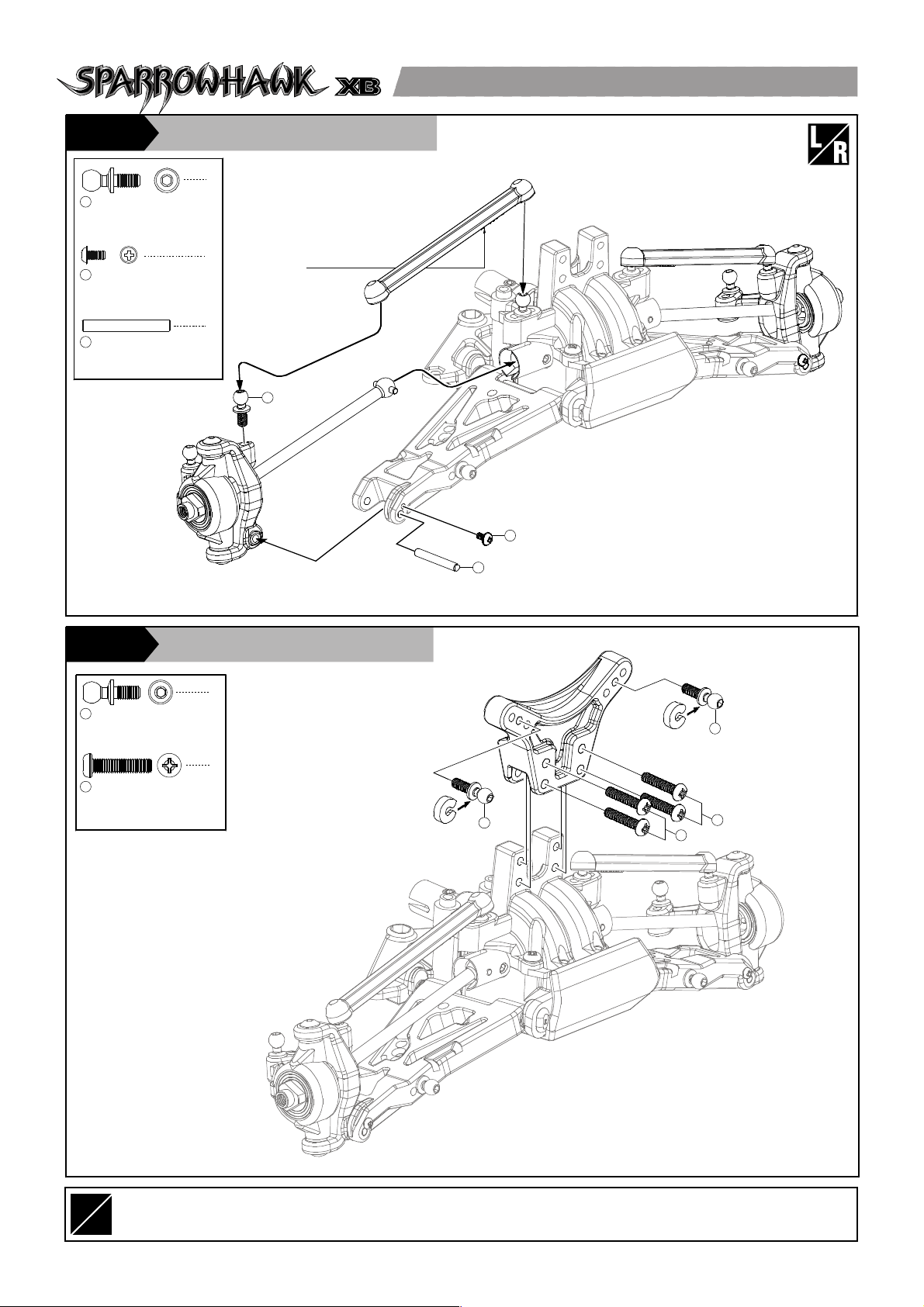
Front Suspension 前擺臂懸吊組
STEP6
1
2
3
2
1
Assemble left and right side the same way
左右側組件相同
8
Front Suspension 前擺臂懸吊組
STEP6
4
3x5 mm
F/H Philip Machine Screw
平頭十字螺絲
1
Front Suspension 前擺臂懸吊組
STEP6
〈Front Bumper〉
〈前防撞板〉
〈For Left〉
〈左側組件〉
3x12 mm
BT Machine Screw
半圓頭內六角螺絲
4
4
10x15x4 mm
Ball Bearing
軸承
1
6mm(L)
Ball Stud
球頭座
2
2
4
Caster Block Bushing
C型輪座
3
4
4
2
4
1
3
3
1
Marked "L"
標示 "L"
Marked "R"
標示 "R"
In the chassis set,
these dog bones have
been assembled in
one-piece unit.
原廠組配已完成
A
B
A B
A B
A
A
Toe Adjustment
前束角調整
For Ready Set Steering Linkage
For Optional Turnbuckle Linkage
適用原廠固定式轉向拉桿
適用改裝可調式轉向拉桿
Apply grease
使用潤滑油膏(黃油)
Hint
組裝提示
1
1
Side View
側視圖
Assemble left and right side the same way
左右側組件相同
9
L
R
2
6mm(L)
Ball Stud
球頭座
1
2
2x4mm
BT Self-Tapping Screw
圓頭十字墊圈螺絲
2
2
2.5x20mm
Outer Hinge Pin (Front)
輪座固定軸
3
Front Suspension 前擺臂懸吊組
STEP6
2
6mm(L)
Ball Stud
球頭座
1
4
3x14mm
BT Philip Machine Screw
圓頭十字墊圈螺絲
2
〈Front Shock Tower〉
〈前避震器支架〉
Front Suspension 前擺臂懸吊組
Marked "B-CM"
標示 "B-CM"
〈For Right〉
〈右側組件〉
1
2
3
1
1
STEP6
2
2

silicon oil
矽油
Piston
活塞
1mm
2mm
4mm
6mm
Assemble as many times as specified
依指示組裝所需數量
STEP7
2.5mm
1
E-Clips
E字扣
Shock Absorber 避震器組
8
1
Attach the shock eyelet onto
2
3
the shock shaft until it
reaches the mark line on
the shaft.
將避震球器頭鎖附於芯軸宜
到球頭上緣到達刻線。
Shock Eyelet
2
避震軸球頭
2.8x1.9 mm
3
O-Ring
O型環
Shock Shaft
4
避震器軸
Shock Shaft
5
避震器軸
4
or
8
Pull down the piston and
slowlly fill in the silicon oil.
The factory set-up of the
shock is #500 of silicon oil
for the front and rear shock
absorbers.
重新裝填矽油時,請先將活
塞及避震軸下拉,然後緩注
入避震器矽油于套筒內。原
廠避震器設定為前後避震器
皆使用#500號矽油。
4
2
Cover the shaft with cloth
before griping it with pliers.
2
組裝避震球頭時,可以用布
料包覆芯軸,以避免芯軸被
尖嘴鉗刮傷。
3
1
5
Add silicon oil one
more time up to the
brim.
等所有氣泡都消失後
再將液面補滿。
X
2
Front x2
前2組
X
4
Eensure the piston move
smoothly
最後再確認避震器活塞是
否移動順暢無阻。
X
2
Rear x2
後2組
Then gently move the shaft/piston
up and down to get rid of the
bubbles.
緩慢地將活塞及避震軸上下移動
使得套筒之氣泡能快點消失。
Use 6 mm preload spacer for front. Use 8 mm preloadd spacer for rear.
使用6mm避震器套筒調整夾片來調整避震器彈簧之鬆緊度。
Hint
組裝提示
Apply silicon oil
使用模型專用矽油
Put the shock bladder onto
the shock body, wipe off
excess oil and tighten the
shock cap.
將避震器封套置於套筒上端
並下壓結合,擦拭多餘之矽
油並鎖上避震器上蓋。
X
2X4
Front x2
前2組
Rear x2
X
2
後2組
Compress the spring
an d install spring cup.
將下定位套固定于彈
簧下緣。
4
X
 Loading...