

Page 1
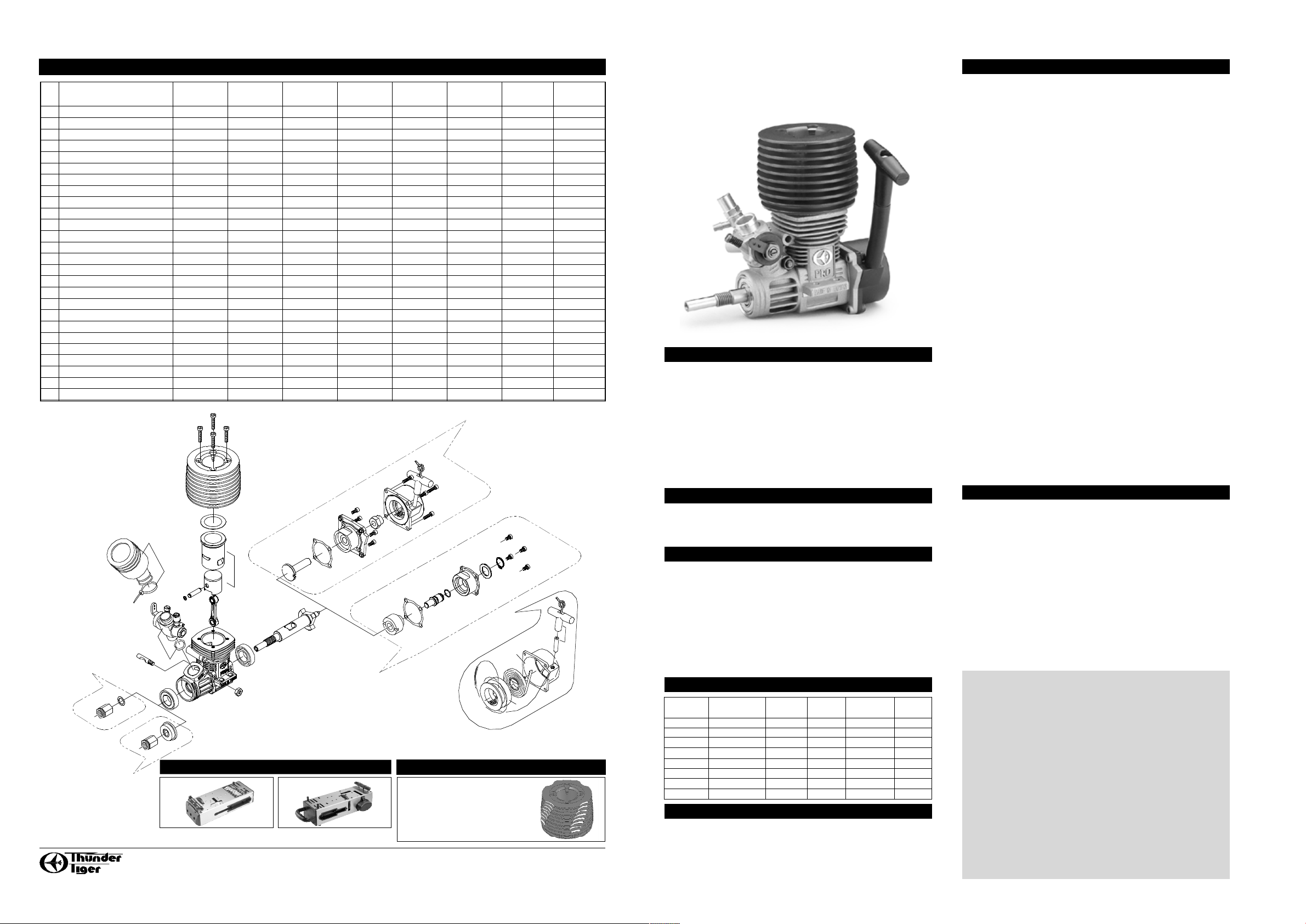
PARTS LIST / ENGINE
THUNDER TIGER CAR ENGINES
INSTRUCTIONS
PRO-18BX / 9442 SHOWN
INTRODUCTION
Congratulations on your purchase of a Thunder Tiger model engine. The
latest Thunder Tiger PRO-12/ 15/ 18 series car engines have been designed
for one tenth scale radio-controlled model cars to combine high performance
with easy handing and maintenanc e using modern CAD compu ter
technology. Majo r components of the engines are mac hined from the
highest quality materials using state-o f-the art CNC manufacturing
techniques, resulting in consistently high performance and reliability. The
PRO series engines are equipped with dual-ball bearings, Schnuerle
porting, ABC type piston and cylinder, and automatic mixture control
carburetors.
IMPORTANT
Be certain to completely read all of the instructions su pplied with your
engine, and pay close attention to the "SAFETY INSTRUCTIONS AND
WARNINGS".
SPECIAL ATTENTION
When you rotate the crankshaft of your engine by hand, you may find that
it becomes rough or "notch" as the piston approaches TDC (Top Dead
Center). This is not a defect or manufacturing fault, indeed it is normal
for an engine of ABC type construction. When the engine runs, the cylinder
actually expands as it heats. The cylinder has been precision machined
so that (at optimum operating temperature) the cylinder walls are perfectly
aligned with the piston. A s the engine cools after a run, you will notice
that the tightness will actually return. This is normal and typical of an ABC
type engine.
LEARNING ABOUT YOUR ENGINE
Before actually operate your engine, the following information is for the
benefit of the newcomers with no previous experience of model engines.
Please put the engine near you and read this instruction. The model engine
is just like the engine of a motorcycle or a car that needs a key to start.
You have to prepare some accessories and knowledge. It is not hard to
operate your model engine by following the instructions properly.
RECOIL STARTING SYSTEM & SHAFT STARTING SYSTEM
The Thunder Tiger "X" type series engines feature a built-in recoil starting
system that eliminates the need for a separate electric starter and battery
or a starter box, and allows the engine to be started easily by simply
pulling the starter handle.
1) Pull the handle straight away from the starter housing so that it prevents
the cord from being damaged by rubbing against the starting wheel
cover or car body.
2) Let the cord recoil slowly while still holding the handle. Do not release
the handle abruptly.
3) It is recommended to keep the cord away from fuel, as fuel will weaken
the cord and cause it to break.
4) The recoil starter system is developed to operate in a counter clockwise
direction (when viewed from front of the engine). If you attempt to crank
the flywheel or force the engine in the opposite direction, the one-way
clutch set will be damaged.
5) The spring in the recoil system is under extreme tension! If it is necessary
to dismantle your engine, remove the starting wheel cover set gently
to prevent damage or injury.
The Thunder Tiger "K" type series engines feature a built-in hexagonal
shaft starting system that can be operated to start the engine as simple
as the "X" type series. Please refer to the instruction of your model
vehicle for the compatibility of installing the "K" type series engine on
your model vehicle.
1) To use the Hex Starting shaft, either a cordless drill or 12V DC handy
starter is required.
2) Install the extended 6mm hex starting tool into the cordless drill or a
12V DC starter.
3) BEFORE inserting the Hex Starting shaft into the back start output,
squeeze the trigger and verify that the drill is turning the same direction
as is shown on the sticker on the back start cover.
4) Attempting to start the motor by using a counter-clockwise direction
could damage the pull-start mechanism or possibly the engine internal
components. Insert the ball end of the Hex Start shaft into the Dual
Start output. Grasp the drill tightly and squeeze the trigger.
NECESSARY ACCESSORIES
The following items are necessary for operating the engine, these are
available at you hobby dealer.
FUEL
A good quality, commercially available fuel containing 25% lubricant and
75% methanol is recommended for break-in/run-in and general usage.
We also recommend castor oil or a castor/synthetic blend only for use
as a lubricant. Fuel containing 10%-30% nitromethane and 20% lubricant
is for use when more power is required. Most fuels containing synthetic
lubricants (only) are much less tolerant of a lean run compared to fuel
that contains castor oil. If availability or local conditions force you to use
a fuel that contains only synthetic lubricant, we suggest that you keep
your needle valve set to a slightly richer setting, allowing more lubricant
to flow through your engine to extend engine life and maintain optimum
reliability. Do not use fuel containing less than 20% lubricant.
CAUTION 1
Methanol and nitromethane are poisonous and highly flammable.
Keep out the reach of small children and keep away from heat
and open flame.
CAUTION 2
Excessive heat can great reduce the life of your engine. Most
of the heat generated by combustion is removed via the
lubricants that are contained in your fuel, and exits the engine
as exhaust vapor. As a precaution, you should periodically
remove the muffler from your engine and visually inspect the
exhaust port and piston. If the outer surface of the piston is
stained a very dark color, it can indicate that your engine may
be overheating. This can be caused by either an excessively
lean needle setting or a lack of airstream across the cylinder
and head.
SPECIFICATION
11
17
12
10
7
8
9
19
15
13
16a
12
1
5
13
16b
4
22
12
20
12
22
12
24
17
20
33
17
12
12
24
17
25
26
23
27
21
33
3
1
28
ITEMS DISPLACEMENT BORE STROKE PRACTIAL OUTPUT
(cc/cu.in.) (mm/in.) (mm/in.) R.P.M. RANGE (BHP/RPM)
PRO12-BK 2.11/ 0.129 13.85/ 0.545 14/ 0.551 3,000-30,000 0.6/ 29,000
PRO12-BX 2.11/ 0.129 13.85/ 0.545 14/ 0.551 3,000-30,000 0.6/ 29,000
PRO12-BXP 2.11/ 0.129 13.85/ 0.545 14/ 0.551 3,000-30,000 0.6/ 29,000
PRO15-BX 2.47/ 0.151 15/ 0.591 14/ 0.551 3,000-30,000 0.7/ 29,000
PRO15-BXP 2.47/ 0.151 15/ 0.591 14/ 0.551 3,000-30,000 0.7/ 29,000
PRO18-BX 2.97/ 0.181 16.2/ 0.638 14.4/ 0.567 3,000-32,000 0.8/ 31,000
PRO18-BKP 2.97/ 0.181 16.2/ 0.638 14.4/ 0.567 3,000-32,000 0.8/ 31,000
PRO18-BXP 2.97/ 0.181 16.2/ 0.638 14.4/ 0.567 3,000-32,000 0.8/ 31,000
No. DESCRIPTION 9442 9443 9444 9459 9486 9487 9488 9489
PRO-18BX PRO-12BX PRO-15BX PRO-12BK PRO-12BXP PRO-15BXP PRO-18BKP PRO-18BXP
1 PROP NUT AA0199B AA0199B AA0199B AA0199B AA0199B AA0199B AA0199B AA0199B
3 DRIVE WASHER SET ******* ******* ******* ******* AA0023 AA0023 AA0023 AA0023
4 CRANKSHAFT AA2024 AA0728 AA0728 AA0728 AA0022 AA0022 AA2176 AA2176
5 CRANKCASE AN2033 AN2020 AN2029 AN2020 AN2020 AN2029 AN2033 AN2033
7 CONNECTING ROD AN2025 AN0433 AN0433 AN0433 AN0433 AN0433 AN2025 AN2025
8 WRIST PIN ASSEMBLY AA2006 AA0134 AA0188 AA0134 AA0134 AA0188 AA2006 AA2006
9 CIRCLIP AA0722 AA0722 AA0722 AA0722 AA0722 AA0722 AA0722 AA0722
10 CYLINDER&PISTON AN2030 AN0918 AN0716 AN0918 AN0918 AN0716 AN2030 AN2030
11 CYLINDER HEAD AA2121-R AA2124-R AA2125-R AA2122 AA2124-R AA2125-R AA2121-R AA2121-R
12 GASKET SET PN0245 PN0250 PN0248 PN0247 PN0260 PN0261 PN0265 PN0266
13 CARB RETAINING BOLT PN0188 PN0188 PN0188 PN0188 PN0188 PN0188 PN0188 PN0188
15 CARBURETOR ASSEMBLY 9785 9784 9785 9784 9784 9785 9785 9785
16a BALL BEARING, FRONT AMV6800Z AMV6800Z AMV6800Z AMV6800Z AMV6800Z AMV6800Z AMV6800Z AMV6800Z
16b BALL BEARING, REAR AMV6800X AMV6800X AMV6800X AMV6800X AMV6800X AMV6800X AMV6800X AMV6800X
17 SCREW SET PN0196 PN0196 PN0196 PN0195 PN0196 PN0196 PN0195 PN0196
19 AIR CLEANER SET 9262 9262 9262 PD1212 9262 9262 9262 9262
20 ONE WAY CLUTCH SET AN0924 AN0924 AN0924 AN0315 AN0924 AN0924 AN0315 AN0924
21 HANDLE SET PN0050 PN0050 PN0050 ******* PN0050 PN0050 ******* PN0050
22 STARTING AXLE AA0923 AA0923 AA0923 AA2017 AA0923 AA0923 AA2017 AA0923
23 STARTING SPRING AA0735 AA0735 AA0735 ******* AA0735 AA0735 ******* AA0735
24 BACKPLATE AN0764 AN0764 AN0764 AN2018 AN0764 AN0764 AN2018 AN0764
25 STARTING WHELL WIRE AA0733 AA0733 AA0733 ******* AA0733 AA0733 ******* AA0733
26 STARTING WHELL AA0721 AA0721 AA0721 ******* AA0721 AA0721 ******* AA0721
27 STARTING WHELL COVER AN0720 AN0720 AN0720 ******* AN0720 AN0720 ******* AN0720
28 STARTING SET ******* ******* ******* PN0267 ******* ******* PN0267 *******
33 STARTING COVER SET PN0246 PN0246 PN0246 ******* PN0246 PN0246 ****** PN0246
9442/ PRO-18BX
9443/ PRO-12BX
9444/ PRO-15BX
9486/ PRO-12BXP
9487/ PRO-15BXP
9489/ PRO-18BXP
9459/ PRO-12BK
9488/ PRO-18BKP
OPTIONAL CYLINDER HEAD
AA2034-R for PRO-18BX
AA2126-R for PRO-12BX/ 12BXP
AA2127-R for PRO-15BX/ 15BXP
9442/ PRO-18BX
9443/ PRO-12BX
9444/ PRO-15BX
9459/ PRO-12BK
9486/ PRO-12BXP
9487/ PRO-15BXP
9488/ PRO-18BKP
9489/ PRO-18BXP
2409 PRO STARTER BOX
OTHER ITEMS OF INTEREST
2408 PITMATE STARTER BOX
JA0460 V4
THUNDER TIGER CORP.
http://www.thundertiger.com
Page 2

CARBURETOR ITEM NO 9784 9785
NO. DESCRIPTION PART# PART#
A CARBURETOR BODY W/ROTOR PN1304 PN1303
B CARB. ROTOR ASSY PN1125 PN1128
C NEEDLE VALVE ONLY PN1035 PN1035
D SPRAY BAR ASSEMBLY PN1036 PN1036
E NEEDLE VALVE ASSY. PN1037 PN1037
F THROTTLE LEVER PN1038 PN1038
G BOLT&FUEL INLET PN1039 PN1039
H THROTTLE ROTOR SET PN1124 PN1127
I O RING SET PN1041 PN1041
J MIXTURE METERING SCREW SET PN1042 PN1042
PRO-12BX/ 12BK/ 12BXP/ 9784
PRO-15BX/ 15BXP/ 18BX/ 18BKP/ 18BXP/ 9785
GLOW PLUG
The type and quality of glow plug used
in your engine will have a maior impact
on overall performance and reliability.
All of the Thunder Tiger engi nes
operate best with a R/C long-type plug
such as Thunder Tiger, K&B, or O.S.
No.8. Fox plug s (while of excellent
quality) have a colder heat range and
may cau se idle or throttle transit ion
problems in smaller engines . Select
the best one by practical tests.
GLOW STARTER
The electric power source for heating
the glow plug.
PLUG WRENCH
Used for tight ing or screwing off the
glow plug. 4-way type (Thunder Tiger
4-way wrench) is preferred.
FUEL FILL BOTTLE OR FUE L
PUMP
Required to transfer fuel into the fuel
tank in your model. A Thun der Tiger
hand-crank pump or an electric pump
are available at your hobby dealer.
INSTALLATION
ENGINE
Locate your engine onto the engine mount on the chassis. Make sure the
gear mesh is smooth without excessive backlash. Set the clearance and
secure the engine mounting screw. Both the top and bottom surfaces of
the engine mount must be absolutely flat and parallel to avoid crankcase
distortion, stress and power loss.
MUFFLER/SILENCER
After the engine is mounted onto your model , secure the muffler to the
engine with two screws equipped with your engine. Be sure to tighten
them firmly. The rear half of the muffler can be rotated to direct the exhaust
residue away.
GLOW PLUG
Use 4-way wrench to screw the glow plug into your engine and do not
over tighten. Be sure to put the glow plug washer between the cylinder
head and glow plug to eliminate gas leakage.
AIR CLEANER
It preven ts damag ing dust an d dirt from being draw n into the engine
through the carburetor. Even minute foreign particles can easily damage
the engine and cause unreliable performance. It is necessary to chec k
the filter element periodly and replace it as required.
PREPARATION FOR STARTING YOUR ENGINE
PRE-ADJUST NEEDLE VALVE
Turn the needle valve clockwise until you begin to feel resist ance. This
is the fully closed position. Do not force the needle valve or you ma y
damage your carburetor! It may be convenient to remember the position
of the mark on the end of the needle valve. Now turn the needle valve
counter-clockwise about 2 1/2-3 turns. This will be a good place to start.
(Turn the needle valve clockwise is to "close" for leaner mixture, while
counter-clockwise is to "open" for richer mixture.)
CHOKING/PRIMING YOUR ENGINE
Turn on your control system and shift the throttl e full to test. Press fuel
pump in your fuel tank twice to prime your engine. The quanti ty of fuel
drawn into the engine by priming is an important factor for starting your
engine successfully. It needs more choke for the first starting and when
the engine is cold.
HEATING GLOW PLUG
Fit the glo-starter or conn ect the 1.2 volt ignition battery onto the glow
plug. The glow plug is made to keep the engine turning after removing
the glow-starter or cutting off the ignition battery. The platinum alloy coil
inside the glow plug is heated by the starter battery current, and remains
hot to keep the engine running even after the electric power is cut off.
STARTING
1) Pull Start/ Starter Box- Turn the flywheel by using an electric starter/starter
box or pull the handle of the recoil starting system to start the engine
with the throttle opening slightly (appro ximately 1m/m). The engine
should fire after one or two tries.
2) Hex Starter- Make sure that your drill/ starter is set to the clockwise
or forward position. Fit the extension starting shaft to the drill/starter
tight. Insert the shaft into the starting output on th e engine and then
power on the drill/starter. The engine should fire after one or two tries.
If the engine becomes flooded: turn off your vehicle, and then the radio.
Remove the glow plug using a glow wrench and then remove the air filter.
Turn the vehicle over to allow any excess fuel in the engine to run out.
Turn the vehicle right side up. Reinstal l the air cleaner. Slowly pull the
start cord about 8 inches, 5 to 7 times. Reinstall the glow plug with the
glow plug wrench. And return to the normal starting procedure.
CAUTION 1
Do not open the throttle beyond the setting position described
above before starting. It can develop enou gh power to injure
people seriously and do substantial property damage.
CAUTION 2
Never operate your engine at high R.P.M without a "load", that
is, with the wheels off the ground. Otherwise, your engine may
be damaged in a few seconds!
STOP YOUR ENGINE
Cut off the f uel supply to the carburetor by pinching the fuel line closed
or disconnect the fuel line at idle.
BREAK-IN/RUN-IN PROCEDURES
Because your Thunder Tiger engine has been precision-made from quality
materials and is an ABC-type engine, a prolonged break-in period is not
necessary. In fact, your engine can be run in your car to break it in.
1) We strongly recommen ded a fu el containing 20 % caster oil or
castor/synthetic blend with no more than 10% nitromethane be used
for break-in. We strongly discourage using fuel containing only synthetic
lubricants during the initial break-in period.
2) Turn the needle valve clockwise to the fully closed position and back
counter-clockwise about 3-3 1/2 turns. Start your engine as described
above.
3) Use the thro ttle-stop screw to set the idle position (with the throttle
opening approximately 1m/m) where the engine runs at a fast idle but
without engaging the clutch. Then, disconnect the battery from the glow
plug.
4) Let the car run down the longest available straight, or at least, around
a wide curve of sufficient radius to permit full-throttle driving and allow
the engine to consume the entire tank of fuel at this needle setting. If
it stops from being over-rich (i.e. dense smoke coming from the exhaust),
close the needle valve 1/8 turn and re-start the engine.
5) All adjustments during break-in will be made to the high speed needle
valve. If your engine stops in the mid-range or does not accelerate
smoothly (when the thrott le is opened fro m any setting above idle),
ple ase adju st the mixture metering screw as describe d in the
CARBURETOR ADJUSTMENT paragraph after break-in.
6) After the first tank full, allow the engine to cool for a few minutes before
re-filling the tank. Then close the needle valve 1/8 turn an d restart .
During the second tank of fue l, run the engine at alternate throttle
settings (i.e.1/2 throttle for 30 seconds, then full throttle for 30 seconds,
etc.) for about half the tank. Advance the throttle to full, and slowly lean
the needle setting (about 1/8 turn at a time) until the highest speed is
obtained (the smoke has thinned to a light gray).
7) At this point, richen the needle setting about 1/8 turn (counter clockwise)
and run a third tank of fuel at this needle setting. After 4-5 runs, your
engine will be completely broken-in and ready for consistent performance.
CARBURETOR ADJUSTMENT
These Thunder Tiger carburetors are specially designed for use with the
high performance Thunder Tiger engines. The y are able to provi de a
proper air-fuel mixture automatically at all throttle ranges from idle to full
speed. The carburetor has been pre-adjusted at the factory, which should
give excellent engine performance in most cases. Large adjustments of
the carbur etor should not be re quired. However, different operation
conditions (such as your choice of fuel, glow pl ug, gear ratio, clutch
engagement point and climate) may make further adjustments necessary
Model fuel contains alcohol, which is hydroscopic (meaning that it attracts
moisture from the atmosphere). This can cause corrosion to the internal
engine parts. After each running session, run all the fuel out from inside
the engine and disconnect the fuel line from the carburet or. Put 4 or 5
drops of after-run oil (Marvel Mystery Oil, Prather, Pacer, etc.) into the
carburetor and turn the engine over by hand several times to protect the
engine bearings and internal parts from corrosion.
The use of after-run oil is also important during periods of prolonged
storage (such as winter). We suggest removing the engine from the model,
and liberally applying oil into the carburetor and glow plug hole, wrap your
engine in a soft cloth and store in a sealed plastic bag.
Do not dismantle your engine unnecessarily, as this may upset precision
fits such as piston/cylinder and crank pin/connecting rod assembly. If it
is necessary to clean your engine completely, remove only the carb. (do
no disassemble), muffler, backplate, and cylinder head . Flush the entire
engine with fresh fuel and reassemble. Apply after-run oi l to the engine
and store or re-install into the model. Do not disassembl e your engine
further than described above.
SERVICE PROCEDURES
Thunder Tiger strives to bring you the highest level of
quality and service we can provide. We race and test
our products around the world to bring you state-of-theart items. Thunder Tiger guarantees that you should
enjoy many hours of trouble free use from our R/C
products. Thunder Tiger products have been sold
worldwide through the authorized distributors that are
supported directly and rapidly from Thunder Tiger. You
may find that Thunder Tiger is always pursuing to explore
new items creatively with highest quality. To update the
latest product information and to get the best technical
support, please feel free to contact your local hobby
shops or Thunder Tiger authorized distributor.
NEEDLE VALVE ADJUSTMENT
This is use d to adjust the high speed fuel mixture. Opti mum setting is
described in the BREAK-IN/RUN-IN PROCEDURES.
MIXTURE METERING SCREW ADJUSTMENT
This is used to obtain a smooth transition and stable idle.
1) After the needle valve has been set, keep running at the highest speed
for about 10 seconds the n abruptly close the throttle to the lowest
speed. Run at idle for about 5 seconds. Then quickly open the throttle.
2) If the engine hesitates before picking up speed, and there is plenty of
smoke and un-burned fuel coming out from the exhaust, the mixture
is too rich. Screw in (clockwise) the mixture metering screw about 1/8
turn.
3) On the other hand, if it speeds up before qu itting, the mixture is too
lean. Screw it out about 1/8 turn.
4) If this is difficult to observe, then allow the engine to idle slightly longer
before opening the throttle. Repeat procedure 1) patiently for few times
to ensure the best running is obtained.
THROTTLE-STOP SCREW ADJUSTMENT
This is used to set the minimum idle speed. If the engine runs too fast at
the lowest throttle opening, turn the throttle stop screw counter-clockwise
to reduce the throttle opening.
ENGINE CARE
Always keep the outside of your engine clean. Use clean, fresh fuel and
keep your fuel can, pump, and fueling system free from dirt particles.
Install a fresh fuel filter between the fuel tank and carburetor, and between
your fuel pump and filling line to prevent any potential of dirt entering your
engine.
B
I
D
G
C
E
J
H
F
A
NO.9281
GLOW PLUG
NO.2150/ 2151/ 2152
GLOW STARTER
NO.1102
PLUG WRENCH
NO.1645
FUEL PUMP
PARTS LIST / CARBURETOR
NOTE 1
The m ix ture m et ering scre w of yo ur
carburetor has been pre-adjusted at the
factory. If it is screwed in or out too far, reset
it as follow:
Screw in or out the mixture metering screw
until its end is flush with the throttle. Then
screw the mixture metering screw out about
1 turn. Now it is the standard position.
1 turn
Mix. Metering Screw
 Loading...