

Page 1
No.6526-F
1:10 ELECTRIC POWERED 2WD TRUCK & BUGGY
No.6525-F
Page 2
Thank you for purchasing the Thunder Tiger PHOENIX stadium truck / buggy. Thunder Tiger strives to bring you
the highest level of quality and service we can provide. We race and test our products around the world to bring
you state-of-the-art items.
This instruction manual contains the steps you will use to prepare and use your new vehicle. Please read all
instructions and familiarize yourself with the systems and controls of this product before operating. You should
enjoy many hours of trouble free use from this advanced R/C produc t. We offer on-line help 24- 7 on our
www.acehobby.com or www.thundertiger.com web site and our product specialists are ready to take your call if
you have any technical questions. Have fun and enjoy the exciting world of R/C.
INTRODUCTION
PRECAUTION
Thanks you for purchasing a Thunder Tiger product. Please read all instructions thoroughly
before operation.
1. This product is not a toy. It is a high performance model product. It is important to familiarize
yourself with the model, its manual, and its construction before assembly or operation.
Children's operating under the supervision of the adults is necessary.
2. Do not operate model products in rain, on public roads, near crowds, near airport, or near
areas with restricted radio operation.
3. This product, its parts, and its construction tools can be harmful to your health. Always
exercise extreme caution when assembling and/or operating this product. Do not touch
any part of model that rotates.
4. Check your radio frequency with the proper operating frequency of the area or country.
Always check if there are any modelers operating on the same frequency as you are. Also,
check your radio for proper operation before operating a model.
5. Use an adequate charger for the batteries and follow the instruction correctly.
6. Right after use, do not touch equipment on the model because they may generate high
temperatures!
7. Do not stall the motor. The ESC may fail if power is applied to the motor when car cannot
move freely.
8. Improper operations may cause personal and/or property damage. Thunder Tiger and its
distributor have no control over damage resulting from shipping, improper building materials,
construction, or improper usage.
9. By the act of assembling or operating this product, the user accepts all resulting liability.
If the buyer is not prepared to accept this liability, then he/she return this product in new,
unassembled, and unused condition to the place of purchase.
10. WARNING: To avoid a possible fire hazard, ALWAYS unplug the battery after use.
Do NOT leave your vehicle unattended with the battery plugged in.
Page 3
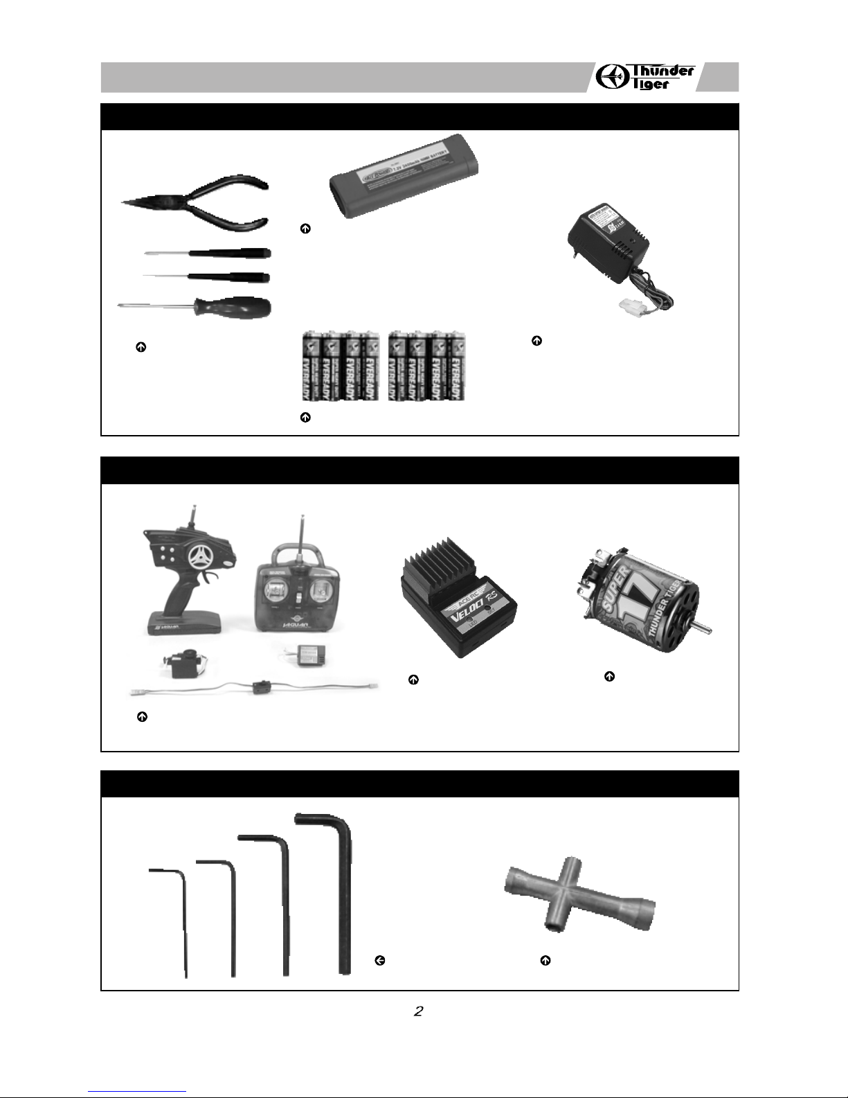
ITEMS REQUIRED FOR OPERATION
ITEMS INCLUDED
TOOLS INCLUDED
Nose Plier,
Philips Screwdriver,
Allen Wrench
Ni-MH Battery Pack
2974 IB Ni-MH Batter Pack, 7.2V/IB3000
2977 IB Ni-MH Batter Pack, 7.2V/IB4200
Power Charger (AC/DC Charger)
2605AC 110V/7.2-8.4V
2606AC 230V/7.2-8.4V (2P)
2607AC 230V/7.2-8.4V (3P)
2-Channel Surface or Pistol Radio
with Standard Servo.
Electric Speed Control
8050 ACE R/C VELOCI RS
Motor
SUPER 17
Hex Wrench Set 4-Way Wrench
For Car
For Transmitter
Alkaline Batteries(8), AA-size
Page 4

1
INSTALLING STEERING SERVO LINKAGE
(Skip if already assembled)
a b
a b
d
a. Find the appropriate servo horn for your servo. Remove the servo horn from your servo and replace
with the stock horn, then fasten with the stock mounting screw. Install the ball end into the servo horn.
Add the dust cover. Attach the mounts with the screws and washers. Add the spacers if you have an
Airtronics servo.
b. Mount the servo with two screws.
c. Assemble the servo link, matching the length to the true scale drawing.
d. Use needle-nose pliers to attach link to ball ends.
2
INSTALLING THE RADIO GEAR
(Skip if already assembled)
a.
Attach speed control to chassis with a piece of double side tape.
b.
Run the wire of the speed control through the battery slot area.
c.
Cut a piece of double side tape, remove the paper from one side, and attach it to the bottom of your
receiver.
d.
Slip the receiver wire through the built-in chassis antenna mount. Remove the paper from the other
side and attach to the chassis as shown.
e.
Plug the small BEC plug into the receiver's on/off switch. Follow the instructions that accompany your
radio receiver system. Use a small zip tie to organize the excess wiring.
d
e
c
c
Page 5

3
PREPARING THE RADIO
4
a. Install 8 AA-size alkaline batteries into transmitter.
b. Install the power pack (Flat type battery pack shown in the picture) and connect to the ESC.
c.
Caution: Check all the wiring and connections before you connect the speed control to a drive battery.
Incorrect polarity will wreck your speed control.
INSTALLING THE BATTERY PACK
(Battery products are not included in kit)
a b
a.
When turning radio on, first turn on the transmitter.
b.
Then, turn on the receiver. When turning off, first turn the receiver off, then the transmitter off.
c.
To reverse the functions of servos, use the s mall, white servo reverse switches located on side of the
pistol transmitter (or the inset servo reverse switches located at the bottom of the stick transmitter).
To trim the servos on pistol transmitter, use the trim switches on side of the steering wheel (the ST.
trims steering, and the TH trims throttle/brake). On a stick transmitter, the trim levers are located
accordingly around the sticks.
d.
Do not run flat the battery of your transmitter in case of losing control of the car.
e. For more details, please check the transmitter instruction manual.
RADIO OPERATION
a
a
5
b
a
c
a. Install the antenna into transmitter.
b.
Check the frequency printed on the transmitter crystal.
c.
Check the frequency printed on the receiver crystal, and make sure it matches with the transmitter
crystal. Make sure no one will operate on the same frequency when you are. When there is a radio
glitch, it will most likely be caused by improper crystal, damaged crystal, or people operating on the
same frequency.
b
c
c
Page 6

d
e f
7
a.
Make sure the motor is disconnected or ensure some other way that the wheels are free to rotate.
b.
Turn the transmitter on.
c.
Connect your battery pack.
d.
Turn the power (ESC) switch on.
e.
Find the supplied tuning wand in the package or a small screwdriver.
f.
Hold the set-up button pressed in for at least 3 seconds using the plastic tuning wand supplied.
ADJUSTING ELECTRIC SPEED CONTROL (ESC)
6
a. Check the radio steering functions. With the radio transmitter and receiver on, turn the steering wheel/stick
to the left. The front tires/wheels should turn left accordingly. If not, flip the steering servo reverse
switch.
b. Return the steering wheel/stick to neutral. The front tires/wheels should point straight forward. If not,
use the steering trim lever to correct it.
c.
Turn the steering wheel/stick to the right. The front tires/wheels should turn right accordingly.
OPERATING RADIO STEERING FUNCTION
a b c
a b c
Page 7

7
g.
The set-up LED now flashes RED/GREEN to indicate that the ESC is in the set-up mode.
h.
Leave the throttle stick at the neutral position and the throttle trim knob/lever in the middle
i. Press the set-up button, the neutral setting is now stored, and the set-up LED lightens GREEN.
j.
Move the transmitter stick to full-throttle
k. Press the set-up button with the stick still in this position
l.
The full-throttle setting is now stored, and the set-up LED lightens RED.
m. Move the transmitter stick to full brake
n. Press the set-up button with the stick still in this position.
o.
The brake setting is now stored, and the set-up LED flashes 3 times simultaneously and then goes
RED/GREEN light still.
CONGRATULATIONS!
Your electric speed control is now completely set-up and ready to run.
Remember this! The transmitter is always the FIRST TO BE TURNED ON and THE LAST TURNED
OFF.
If you make a mistake during the set-up procedure, don't worry: disconnect the battery for about 10
seconds and start again from the first step.
Refer to the instruction manual for more information on setting the electric speed control.
ADJUSTING ELECTRIC SPEED CONTROL (ESC)
(Picture shows the Ace R/C "Veloci-RS" electric speed control pre-installing on PHOENIX Ready-To-Run
version). Before operating your model, you have to set to either NEUTRAL, HIGH SPEED and BRAKE
position of the electric speed control prior running the motor.
g
h i
j
k l
m
n o
GREEN / RED GREEN
RED
GREEN / RED
Page 8

a.
Make sure that the battery pack is completely discharged prior to charging. Discharging the battery
pack by running the electric motor until it slows down or using a discharger (Not included).
b.
For best results, let the battery pack cool before charging. Heat may prevent the battery pack from
charging to full capacity and also decreases the performance of the battery.
c.
Once the battery ready to be charged, first plug the AC quick charger into the outlet of AC power
source, and then connect the battery input/output harness to the charger.
d.
Continued to monitor the battery as it is being charged. As soon as the battery is fully charged,
disconnect the battery. from the charger plug (Over-charging or charging incorrectly using inadequate
chargers may cause the battery pack to become dangerously hot).
BATTERY CHARGING
(Battery products and charger are not included in kit)
9
1
CONNECT BATTERY PLUG
TO DC OUTLET PLUG FROM CHARGER.
PLUG INTO AC OUTLET.
2
AFTER CHARGE TIME EXPIRES, DISCONNECT
BATTERY PLUG FROM CHARGER PLUG.
3
MAINTENANCE AFTER RUNNING
a.
Always turn off the radio system and disconnect the battery pack when the car is not in use.
b.
Remove the sand, mud, dirt, and any other elements completely from the car before you store it.
c. Never use chemicals or any solvents to clean the chassis as it may cause damage to the electronics
components and plastic parts as well. Use compressed air, soft paintbrush, or toothbrus h to clean
dust and dirt.
10
JD6901.V3
VELOCI SPECIAL FEATURE
The VELOCI digital speed controls feature a new overheat protection function. This function protects
the VELOCI against overheating during operation. If the speed controls temperature exceeds safe levels,
the motor function will be temporarily switched off. However, full steering function is still maintained during
this period. When the overheat protection mode is activated, the setup LED will flash GREEN and RED
simultaneously. Simply wait a few minutes to allow the speed control to cool down to normal operating
temperatures and full function will be restored.
Overheating may be caused by the following:
a. Driving in reverse in excess of 8 seconds.
b. The motor used has less than factory limit of turns.
c. Gear mesh is too tight or other drivetrain problems.
d.
Inappropriate gear ratios.
e. Repeatedly going from full reverse to full forward instantaneously.
f. Using full brakes too often.
g.
Not enough ventilation to the speed control.
8
 Loading...