

Page 1
MEMO
Assembly Manual
Specifications:
Fuselage Length (less rotor): 49" (1245mm)
Fueslage Width (less rotor): 18.75"(475mm)
Full Equipped Weight: 7.7 lbs (3500g)
Hughes 530 MD Scale Fiberglass Fuselage (TTR3837)
Warranty
This kit is guaranteed to be free from defects in material and workmanship at the date of purchase.
It does not cover any damage caused by use or modification. The warranty does not extend
beyond the product itself and is limited only to the original cost of the kit. By the act of building this
user-assembled kit, the user accepts all resulting in liability for damage caused by the final
product. If the buyer is not prepared to accept this liability, it can be returned new and unused to
the place of purchase for a refund.
Notice: Adult Supervision Required
This is not a toy. Assembly and flying of this product requires adult supervision.
Read through this book completely and become familiar with the assembly and flight of this MD-
530. Inspect all parts for completeness and damage. Browse www.thundertiger.com for customer
service if you encounter any problems.
16
JK6014
1
Page 2
INTRODUCTION
PRE-ASSEMBLY NOTES
Congratulations on the purchase of our finest scale heli fuselage to date. This famous Hughes MD 530 (Military Defender),
used as an antitank, multi-mission helicopter under extreme conditions. The venerable MD 530 has been replicated to
exhibits this attack helicopters' sleek details. The light fuselage comes factory pre-painted with all necessary hardware. It
is very easy to assemble and only takes you few hours of enjoyable installation to put this scale body on your helicopter.
This replica MD is just like a real thing, hovering this MD that will definitely make you stand out on the flying field.
PRE-ASSEMBLY NOTES
Before beginning the assembly read the instructions thoroughly to give an understanding of the sequence of steps and a
general awareness of the recommended assembly procedures.
By following these instructions carefully and referring to the corresponding pictures, the assembly of your model will be
both enjoyable and rewarding. The result will be a well built, easy to assemble scale model, which you will be proud to
display.
This MD-530 is designed for intermediate to advanced pilots, and this manual assumes a basic knowledge of R/C model
construction.
BEFORE YOUR ASSEMBLY
1. Before you start to assemble this fuselage on your helicopter, we suggest you to first fine tune your helicopter in the air.
2. Double-check all screws, then secure and Loctite all the loose screws.
3. The instruction manual is written for Raptor 50, if user should choose to install it on other branded helicopters, we would
suggest you to study the manual thoroughly and see how it installed on a Raptor 50.
Before you begin, check the entire contents of your kit against the parts list and photos to make sure that no parts are
missing or damaged. This will also help you to become familiar with each component of your model. If you find that any of
the parts are either missing or damaged, please contact your local Thunder Tiger authorized distributors for replacements.
Neither your dealer nor Thunder Tiger authorized distributor can accept kits for return if construction has begun.
Trial fit each part before gluing it in place. Make sure you are using the correct part and that it fits well before assembling.
RECOMMENDED TOOLS & MATERIALS
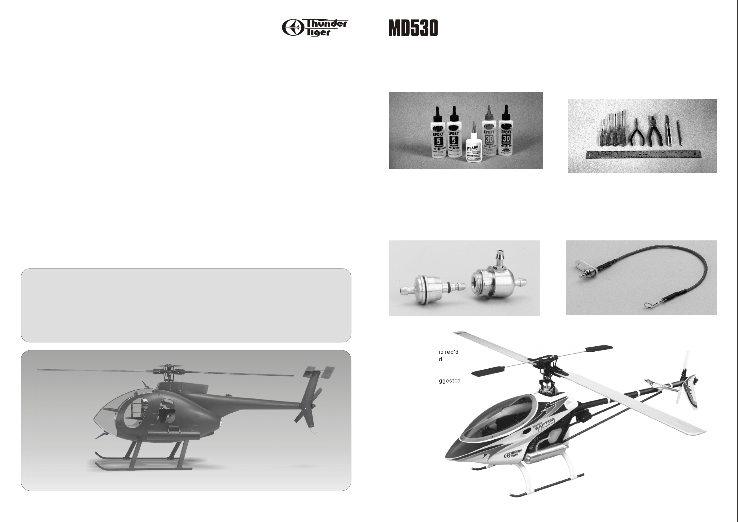
Adhesives:
Instant setting Cyanoacrylate adhesive (thin CA)
Slow setting Cyanoacrylate adhesive (thick CA)
10 Minute Epoxy (fast)20~30 Minute Epoxy(slow)
You will need two types of adhesives for the MD-530 Epoxy and Instant (cyanoacrylate) adhesives. We
recommend that you purchase both 5-minute and 30minute epoxy to cut down on assembly time, but you can
get by with only 30-minute epoxy if time is not important.
You will also need a small bottle of both "Thick" and
"Thin" instant CA adhesive.
ITEMS YOU MAY NEED
Tools:
Model Knife, 1/2" MASK Tape, Small & Medium Screwdrivers, Scissors, Long nose Pliers & Diagonal Cutting
Pliers, Drill and Drill Bits (1/16", 5/64"), 150 Grid Sand
Paper, Fine Felt Tip Pen & Soft Lead Pencil, Reamer
Model assembly can be much easier if the proper tools
are used. Therefore, we have included in our checklist
to the left, a complete listing of all the tools we used to
assemble our prototype models. As you will notice,
many household tools can be utilized during
construction.
TABLE OF CONTENTS
Introduction....................................................................................................................................................2
Recommended Tools & Materials......................................................................................................................3
Item You May Need..........................................................................................................................................3
Parts Drawings.............................................................................................................................................4-5
Parts Check List..............................................................................................................................................6
Assembly...................................................................................................................................................7-13
Test Flight.....................................................................................................................................................14
MEMO..........................................................................................................................................................16
TTR1115 - Precision Fueler Valve
R/C System:
6 Channel Heli radio req'd
GYRO system req'd
Helicopter:
Raptor 50 Titan Suggested
TTR3803 - Remote Glow Adapter
TTR4853 - Raptor 50 Titan
32
Page 3
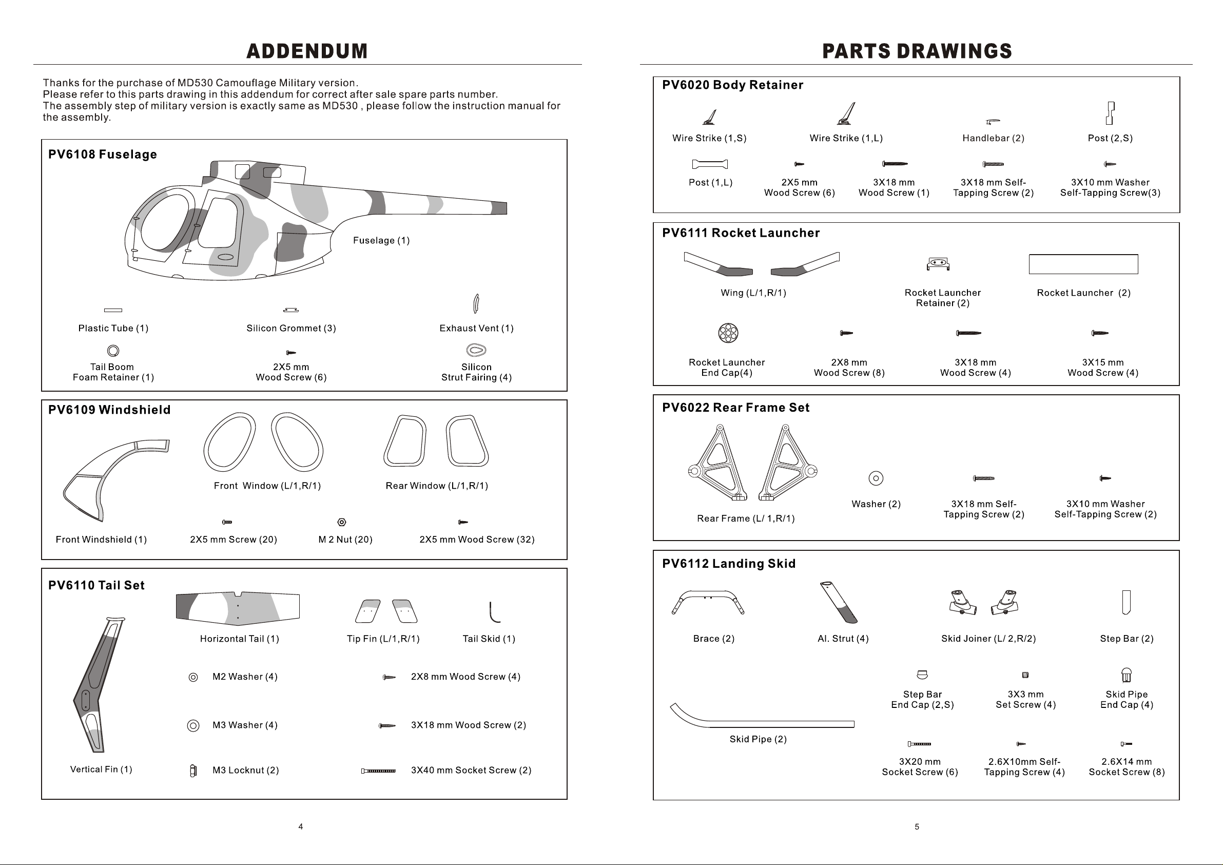
Page 4

PARTS CHECK LIST
ASSEMBLY
1. Note the orientation of the rocket launcher wing and
trail fit in the place on fuselage. Ascertain the two wings
are at same dihedral angle, adjust it until you obtain a
satisfactory result, then use pencil to make marks on
the wing at both sides as guidelines.
3. Epoxy two wings in the place, either wipe off the
excess epoxy or use masking tape to tape the
guideline to keep the wing root clean after the masking
tape removal. Make sure the two wings are at same
dihedral angles. If you see from the top the wings
should be in line with each other or the rocket launcher
will not be straight forward.
Kit Contents
Fuselage
Fuselage(1)
Plastic Tube(1)
Tall Boom Foam Retainer(S,1)
Silicon Grommet(3)
Exhaust(1)
Decoration(1)
Silicon Strut Fairing(4)
Windshield
Left Front Window(1)
Right Front Window(1)
Left Rear Window(1)
Right Rear Window(1)
Front Windshield(1)
Tail
Horizontal Tail(1)
Tip Fin(2)
Tail Skid(1)
Vertical Fin(1)
Body Retainer
Wire Strike(1,S)
Wire Strike(1,L)
Handlebar(2)
Post(2,S)
Post(1,L)
Rocket Launcher
Wing(L,1)
Wing(R,1)
Rocket Launcher Retainer(2)
Rocket Launcher(2)
Rocket Launcher Vent(4)
Landing Skid
Brace(2)
Al.Strut(4)
Skid Joiner(L/2)
Skid Joiner(R/2)
Step Bar(2)
Skid Pipe(2)
Skid Pipe End Cap(4)
Step Bar End Cap(2)
Rear Frame
Rear Frame(L/1)
Rear Frame(R/1)
Washer(2)
Screw
M2 Nut(20)
M2 Washer(4)
M3 Washer(4)
M3 Locknut(2)
2X5mm Screw(20)
2X5mm Wood Screw(44)
2X8mm Wood Screw(12)
3X15mm Wood Screw(4)
3X18mm Wood Screw(7)
3X3mm Set Screw(4)
2.6X10mm Self-Tapping Screw(4)
3X18 mm Self-Tapping Screw (4)
2.6X14mm Socket Screw(8)
3X20mm Socket Screw(6)
3X40mm Socket Screw(2)
3X10mm Washer Self-Tapping Screw(5)
2. Remove the wing to sand away the paint at the glue
area with150 grid sand paper to enhance the adhesion.
Remove the paint in the wing mount by scratching with
a hobby knife inside the well.
4. Next drill two 5/64" (2mm) holes through the wing
mount to the wing from the inside of the fuselage then
secure the wing firmly with two 3x15mm Wood Screws
at each side.
5. Locate the molded marks for landing strut, screw
holes and engine cooling openings at the bottom of the
fuselage. Note these marks are only for reference of
Raptors, shall you install it on other branded
helicopters then you will have to find out the correct
opening position for landing strut before you drill or
trim the fuselage.
76
Page 5

Note: It is recommended to enlarge the strut hole for
about 2~3mm wider as the Silicon Fairing will be
installed in the hole. Do not glue the Silicon Fairing at
this step. It is very important to make sure that silicon
fairing is loosened in the hole instead of tight.
6. Put the scale fuselage aside for a moment and get
your heli prepared. For Raptor owners, please remove
the Landing Skid, Muffler, Tail Fins, Boom Supports
and Tail Rotor Assembly. Locate the Extended Rear
Frames, which are specially designed for this MD
fuselage. Secure the Extended Rear Frame in place
with the screws and washers. (3x18mm self tapping
screw for the top; 3x 10mm washer self-tapping screw
and big flat washer for the bottom).
8. Remove the landing skid assembly from Heli.
Remove the brace from the aluminum strut. Do not
remove the strut and skid pipe as they are already
adjusted and secured. Place the brace in place and
install the strut and skid pipe onto the brace. You may
apply Vaseline on Silicon Fairing to increase the
lubrication for easier installation.
10. Install the lower post which is under the brace, drill
8mm hole and install the Silicon Grommet. Secure the
post in place with 3x10 washer self-tapping screw from
bottom and 3x18mm self- tapping screw from top.
12. If you use Raptor 50 Titan Version then it does not
need to trim anything but if you use on Raptor 50 V2 or
old version then you might need to trim off the fuselage
tail for about Remove the tail rotor
7/8" (20mm).
assembly, landing brace and body retainer from Raptor
then place the Raptor in the fuselage. Next install the
tail rotor assembly in place and check if holes on the
landing brace matches the side frame landing skidmounting holes. If it cannot reach the holes then trim
the tail until it is able to do so.
7. Assemble the Landing Skid as shown. Temporarily
install the Brace under the side frame. Adjust the
Landing Skid as shown and make sure it sits on the
table firmly. Secure the Joiner & Skid Pipe with the
furnished 3x3mm Set Screws. Do not over-tighten the
setscrews; just make sure the skid pipe will not rotate.
Then secure the Joiner and the Aluminum Strut with
2.6x10mm Self-Tapping Screws. Next press the end
cap on skid pipe.
9. Secure the Aluminum Strut and Brace with
2.6x14mm Socket Screws. Hint: Install the left
Aluminum Strut Assembly and Brace first. Pull the
brace out and secure the socket screws then push it
back and pull the right side out then install the right
aluminum strut assembly.
11. Drill two holes for handlebar one is 5/64" (2mm) and
the other is 1/16" (1.5mm). Secure the handlebar in
place with 2x5mm wood screw.
13. Remove the tail rotor assembly and proceed to
extract the Raptor from fuselage. Replace the old post
with the new plastic post mount with 3x18 self-tapping
screw. Place the Raptor into the fuselage again, the
post should be located near a molded dot on fuselage.
14. Drill the hole on the molded dot. Next enlarge the
hole at about 8mm in diameter. Insert the Silicon
Grommet on the hole. The smaller side faces outside.
98
Page 6

15. Unthread the ball link and install the sponge on the
tail boom section where the plastic tube for the sponge
insertion. CA the tube in the sponge but be careful not
to apply any glue inside the plastic tube and make sure
the pushrod can move freely.
Thread the ball link back to pushrod at the original
position.
Glue the sponge on tail boom but make sure the sponge
will tight-fit in the fuselage.
If Raptor 50 Titan is used then the position of sponge is
about 1-1/2" (40mm) to the end of boom.
If Raptor 50 V2 is used then the position of sponge is
about 1-1/8"(28mm) to the end of boom.
17. Secure the helicopter onto the landing brace with
four 3x20mm Socket Screws. Star from the rear brace
then the front.
Now you can CA the Silicon Landing Fairing in place.
18. Secure the fuselage with 3x10mm washer selftapping screw as shown.
20. Trial fit the Horizontal Tail onto the vertical fin, note
that flat surface should be facing up and the other side
with the air foil facing down. It might be necessary to
file/sand the contact area on the vertical fin so that
they make perfect contact. Apply epoxy at the contact
area and make sure it is perpendicular after securing it
with two 3x18mm Wood Screws and two M3 Washers.
Secure two vertical Tip Fins onto horizontal tail with
four 2x8mm Wood Screws and M2 washer.
22. Install the wire strike on the front windshield. The
big one is at the bottom and small one is on the top.
Use 2x5mm wood screws to secure the strike in place.
23. Install the front windshield with twenty 2x5mm
screws and M2 nuts. Carefully make drill marks and
drill 5/64" (2mm) holes then secure the front windshield
in place. Apply Loctite for each screw and nut.
16. Insert the tail boom into the fuselage again and sit
on the brace, make sure the sponge is tightly fit in the
tail and secure the tail boom firmly. Check the pushrod
movement is freely without binding and adjust it if
necessary. Install the tail rotor assembly in place
firmly and snap on the ball link.
Note: do not glue sponge in the fuselage in case you
had to remove the heli from fuselage.
19. Secure the Vertical Fin in place with two 3x40 Socket
Screws, two M3 Washers and two M3 Locknuts.
21. You will have to install the remote glow plug
adaptor (TTR3803). for easy glow ignition. Also install
a diverter and drill an exit hole at the bottom of the
fuselage or you may extend the diverter to fuselage
exhaust vent to obtain a more scale-like look.
24. Trail fit the windows and you may need to trim the
fuselage to get a better fit. Next make drill marks and
drill 1/16"(1.5mm) holes then secure the front side
window with eight 2x5mm wood screws. After you
done the installation of the window then peel away the
protecting film.
You may skip the installation of rear side windows as it
is easier for you in case of tuning engine or adjustment
and it also gets better cooling.
1110
Page 7

Test Flight
1. When hovering you MD, try to keep rotor speed at approximately 1600~1700 RPM.
2. Check the helicopter and fuselage to see if any screw loosened after each flight.
3. It is might be easy to get nose up in speed flight, please trim the elevator down when switching on the idle.
25. Locate the vacuum formed decoration and place it at
the center line of the tail section. Drill two 1/16" (1.5mm)
mounting holes and secure it with two 2x5mm Wood
Screws.
26. Locate the Rocket Launcher Retainer and center it
on the Launcher. Make marks and drill 1/16" (1.5mm)
holes then secure it with four 2x8mm Wood Screws. Do
the same procedure on the other launcher but note the
orientation of the other retainer. Glue the vents on the
launcher.
28. Secure the exhaust vent in the place with four 2x5mm
wood screws as shown.
29. Secure step bar on the strut with 3x20mm socket
screw. Apply Loctite and do not over tightened the
screw. Next press on the step bar end cap in place.
27. Use the retainer hole as the guide to make a drill
mark on the wing. Drill 5/64"(2mm) holes. Next apply
epoxy at the contact area and secure the retainer on
the wing with two 3x18mm Wood Screws. Do the same
procedure on the other launcher and make sure two
launchers are parallel and aim to front.
30. Drill 5/64" (2mm) hole then apply epoxy or thick CA
next thread the tail skid at the bottom of vertical fin.
1312
Page 8

No.4853
1514
 Loading...