

Page 1

1
Wireless video transmitter
Precautions
• Safety
This equipment contains heat sensitive components. Maximum ambient
temperature must not exceed 35° Celsius.
Humidity in rooms where this equipment is situated must not exceed a hygrometric
level of 85 %. If you have to use your equipment outside, avoid exposing it to rain
water or to splashes. The transition from a cold environment to a hot one may cause
condensation. Allow it to dry by itself before re-starting the equipment.
In the event of prolonged absence, switch off the equipment by means of the on/off
switch. Even when switched off, certain components remain live. In order to insulate
it completely you must remove the plug from the main electricity supply.
In the event of an electrical storm, it is advisable to disconnect the equipment from
the electricity supply so as to avoid potentially damaging electrical or
electromagnetic surges. To this end, make sure that the mains plug is easily
accessible for disconnection.
Disconnect the equipment immediately if you detect a smell of burning or smoke.
Under no circumstances must you open the equipment yourself; you run the risk of
electrocution.
• Maintenance
Clean the equipment with a soft cloth and a neutral detergent. The use of solvents,
abrasive products or alcohol-based products is likely to damage the equipment.
• Regulations
This equipment must only be installed inside. Its use is restricted to private radio
transmission. Connection to a public or independent network, or to an outside aerial
is prohibited.
Under no circumstances should this appliance be put to industrial use. It is designed
solely for domestic operation.
THOMSON disclaims all responsibility in the event of use that does not comply with the
present instructions.
en
VS360/460 - 5 langues 12/02/03 10:45 Page 1
Page 2
2
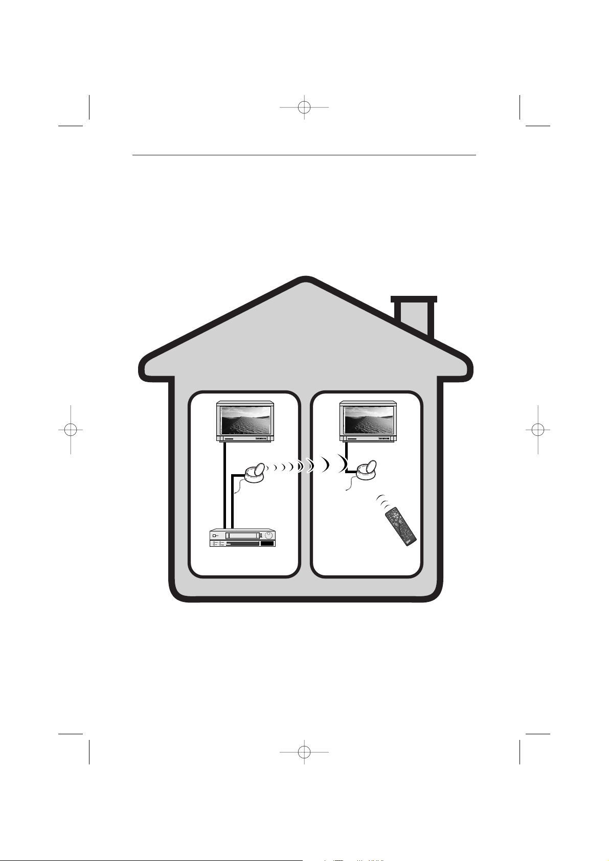
LIVING ROOM BEDROOM
Transmitter
Video recorder,
satellite receiver,...
Receiver
Remote control for
video recorder,
satellite receiver,…or
universal remote
control.
Principles of operation
VS360/460 - 5 langues 12/02/03 10:45 Page 2
Page 3
3
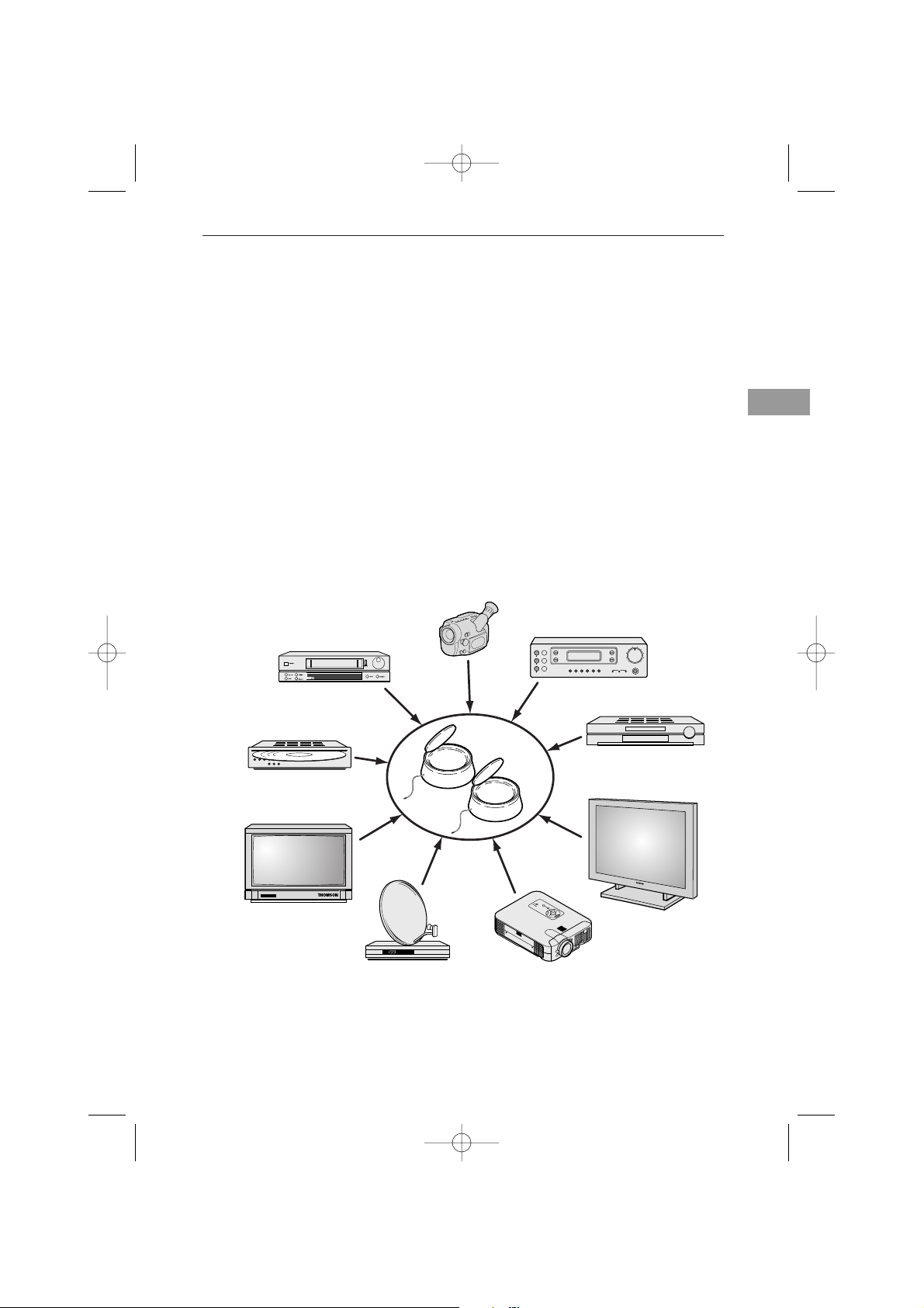
The Video Sender VS 360/460 permits the relay of an Audio-Video signal from your
main set-up to a second television set located in another room and equipped with a
scart connection (or RCA/Cinch). The main set-up is the place in which you have
chosen to install the majority of your equipment (television set, video recorder,
satellite receiver, DVD player,..) you can operate the units from the room with the
second television set by using their remote controls, or with a universal remote
control.
You can play and hear music if you connect the transmitter to a suitable outlet
(
AUDIO OUT), and the receiver to an amplifier (AUDIO IN) placed in another room. For
the link-up you will need to obtain 1 cinch/cinch cable (not supplied with
equipment).
If you already have a Thomson plasma screen monitor or video projector, the Video
Sender will ease your placing of these items where you most want them to be, thanks
to eliminating all problems related to long cable runs.
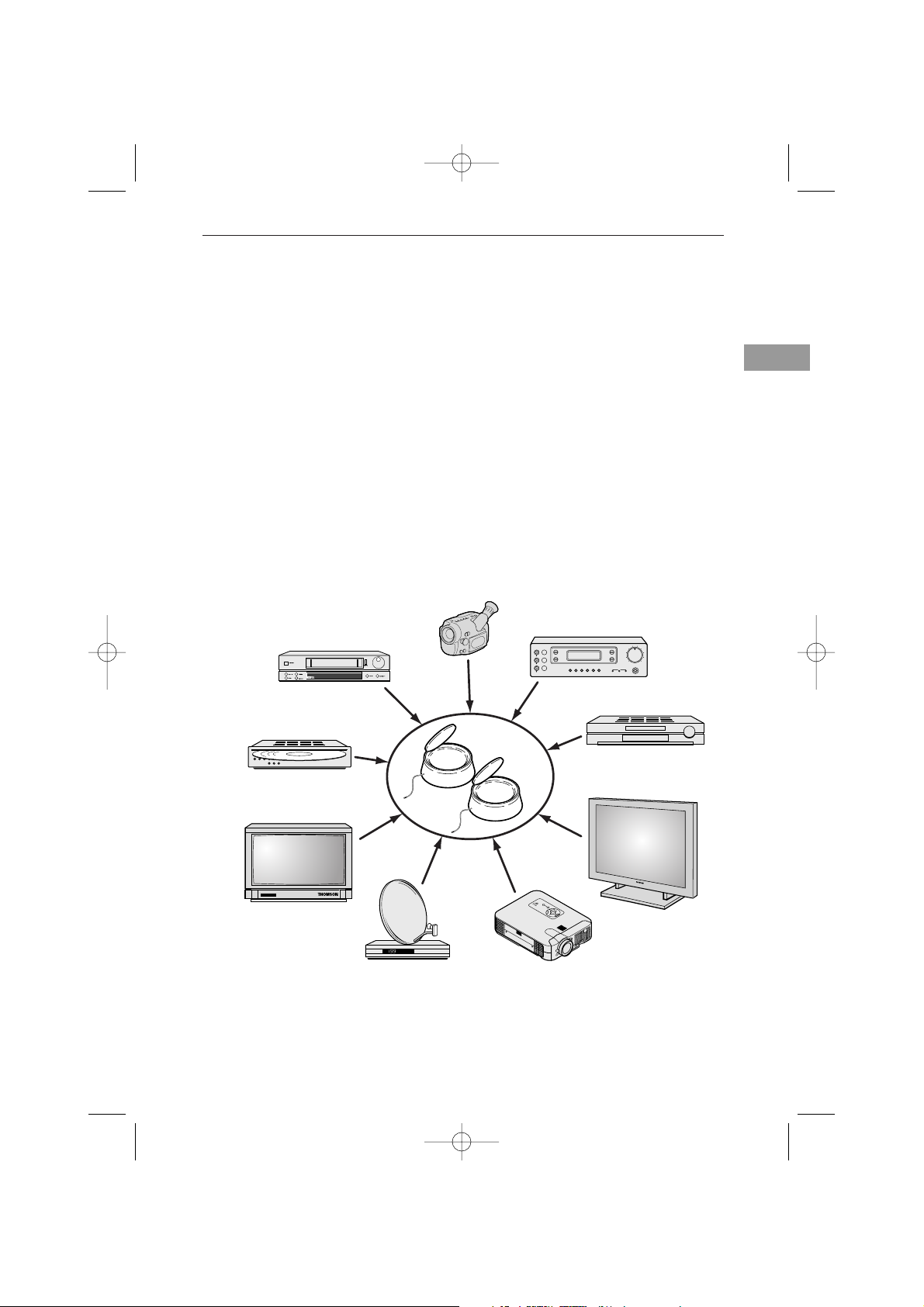
What is this equipment for?
M
E
N
U
E
N
T
E
R
C
A
N
C
E
L
SE
LE
CT
PO
W
ER
STATUS
O
N
/
S
TA
ND
BY
S
OURC
E
AU
TO
A
D
JUS
T
PC
CA
RD
A
C
CESS
DVD player
Plasma screen monitor
Television set
Video recorder
Camcorder
Video disc player
Satellite/Cable receiver
and decoder
Video projector
A/V Amplifier
en
VS360/460 - 5 langues 12/02/03 10:45 Page 3
Page 4

4
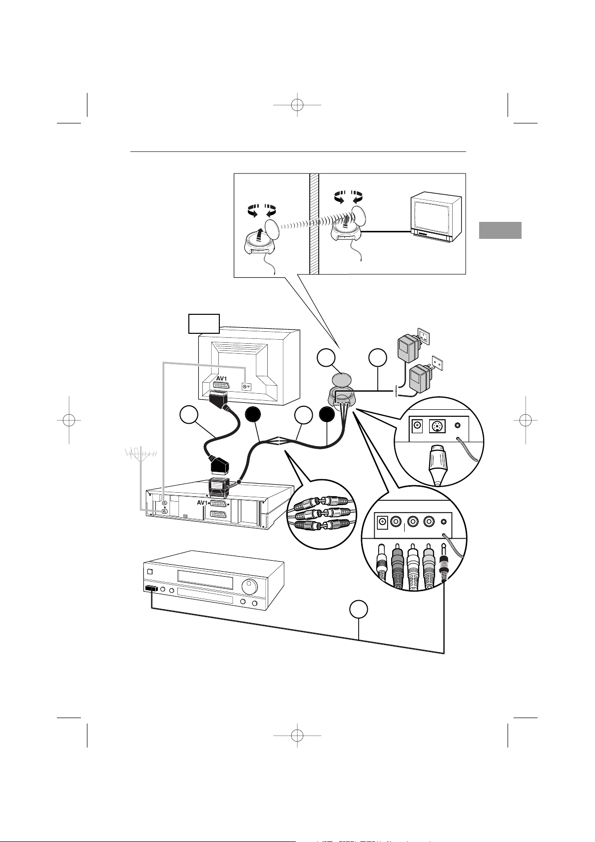
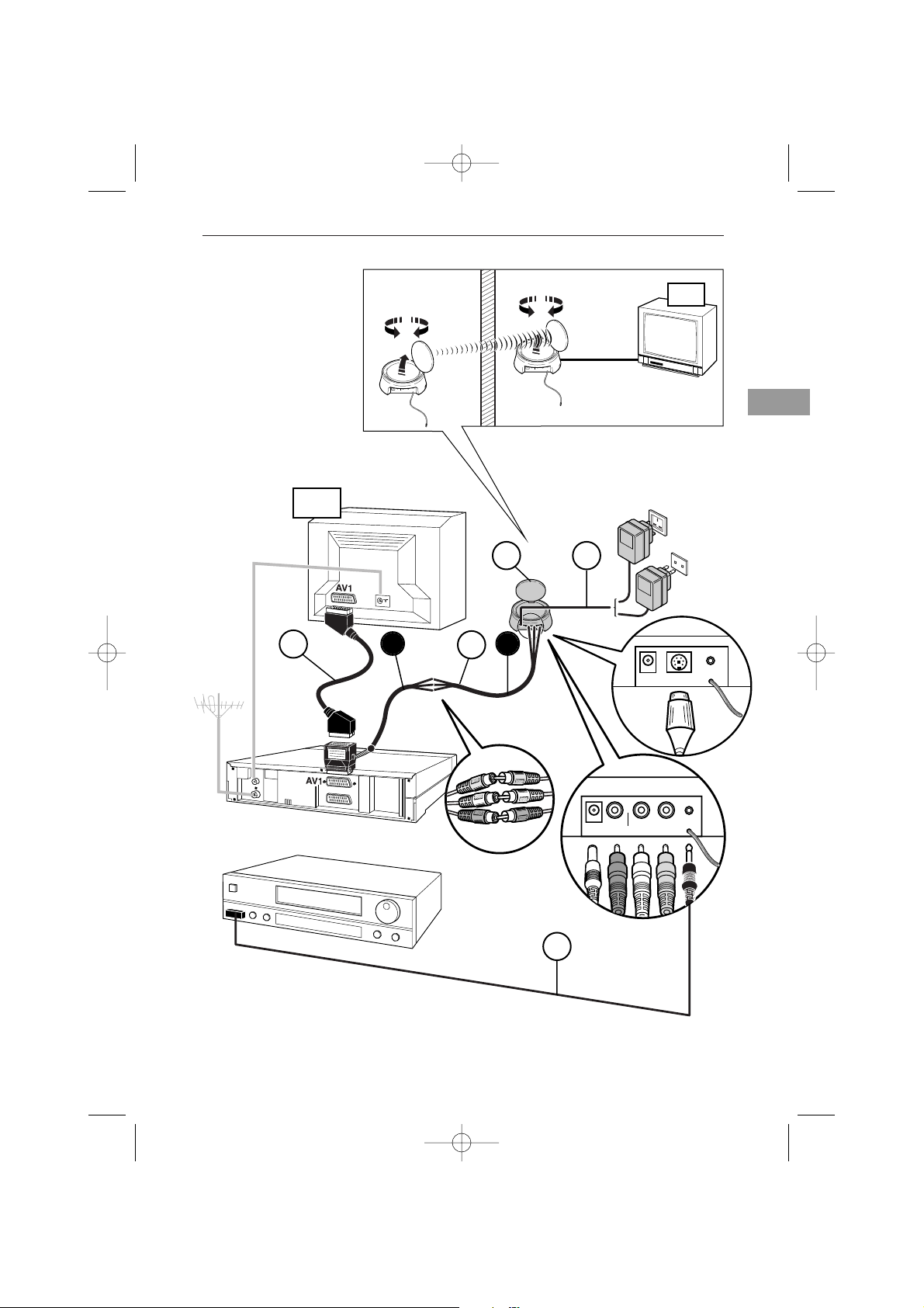
1. Place the transmitter (1) near the source equipment (VCR player, DVD player,
etc.) from which you want to transmit video or audio output, and connect it with
the two cords (2 A and 2 B) making sure you respect the color coding of the 3
cinch plugs (red and white for audio, yellow for video). Connect the TV set to a
suitable outlet from the VCR player or DVD player (AV1).
Obtain a (non-supplied) SCART-TV set connector and connect the TV set to the
2B adapter already connected to the VCR player or DVD player as shown on
Page 5 (see item marked
*
on Page 5).
2. Carefully extend the antenna of the transmitter (1) and orient it towards the room
where your second TV set (TV2) is located. Turn on (position ON) the transmitter
and receiver, using the ON/OFF switch located on its lower side. Place the
channel selectors of the transmitter and the receiver on the same channel (same
letter).
3. Fit the lead (4) following these stages:
- connect the jack plug to the IR EXTEND socket,
- unwind the lead and place one cell near the infrared window of the unit to be
operated (video recorder or other),
- after installing the receiver (see Pages 6 and 7), ask someone to use the remote
control of that equipment item to be controlled from the room where the second
(TV2) is located,
- by moving the cell around in front of the unit to be operated you will find the
location that permits its control from the other room. You must fix the cell in that
position. Usually, this will be a more or less large, transparent area located on the
front of the unit.
4. Remove the protective self-adhesive film from the infrared cell of cord (4) and affix
it to the infrared-sensitive panel of the equipment to be remote controlled. The
cordon has 3 cells in order to let you play video and audio from 3 equipment items
connected to the (TV1) set (see Diagram 2 on Page 10).
5. Fit the mains supply lead (3) to the transmitter and plug it into a 220/240 V ~ 50 Hz
mains power supply.
Installation of transmitter
VS360/460 - 5 langues 12/02/03 10:45 Page 4
Page 5
5
en
AUDIO IN DC 12VVIDEO INIR OUT
LEFT RIGHT
DC 12V
IR EXTEND
AV EXTEND
AUDIO IN
DC 12V
VIDEO IN IR EXTENDLR
AUDIO IN
DC 12V
VIDEO INIR EXTENDLR
2
1
3
4
220/240V ~ 50 Hz
TV1
*
A
B
UNITEDKINGDOM EIRE
VS 360
VS 460
CONTINENTAL
EUROPE
VS360/460 - 5 langues 12/02/03 10:45 Page 5
Page 6
6
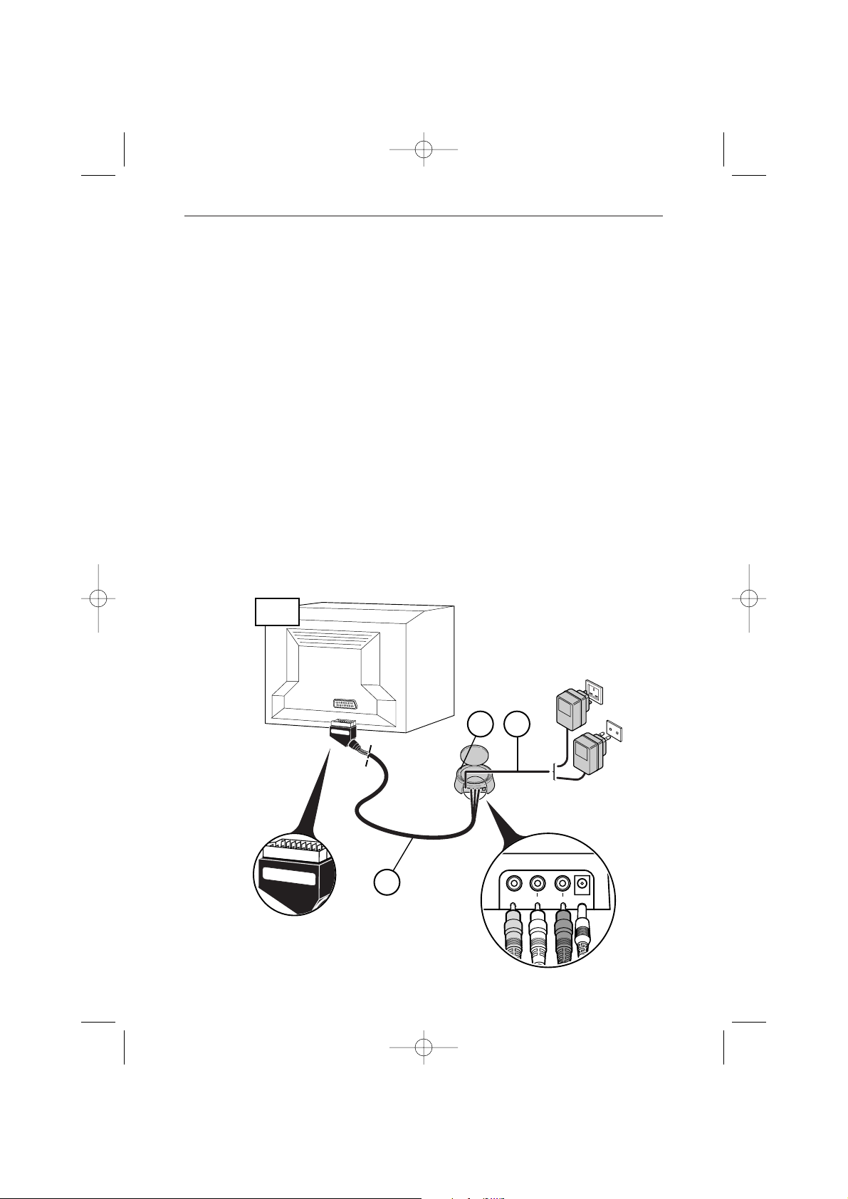
1. Place the receiver (5) on, or near, the second television set.
2. Connect the receiver (5) to the second television set using the lead (6) following
the same instructions as for the transmitter.
3. Extend the antenna on the receiver (5) and orient it toward the main TV set (TV1).
4. Fit the mains supply lead (7) to the receiver and plug it into a 220/240 V ~ 50 Hz
mains power supply.
! THE ANTENNA allows you to transmit and receive audio and video signals over a
maximum range of 30 meters in free air environments. Inside a typical lodgment the
range will be less because of signal attenuation by building material absorption.
! THE FLEXIBLE ANTENNA permits the control of the unit whose pictures you wish
to see in the room containing the second television set (TV2).
! THE POWER SUPPLY plug fitted to the transmitter (1) is not the same as the one
fitted to the receiver (7).
Installation of receiver
AUDIO IN DC 12VVIDEO INIR OUT
LEFT RIGHT
R
e
c
e
i
v
e
r
Receiver
AUDIO OUT
LR
DC 12VVIDEO OUT
6
TV2
5
7
220/240V ~ 50 Hz
UNITEDKINGDOM EIRE
CONTINENTAL
EUROPE
VS360/460 - 5 langues 12/02/03 10:45 Page 6
Page 7
7
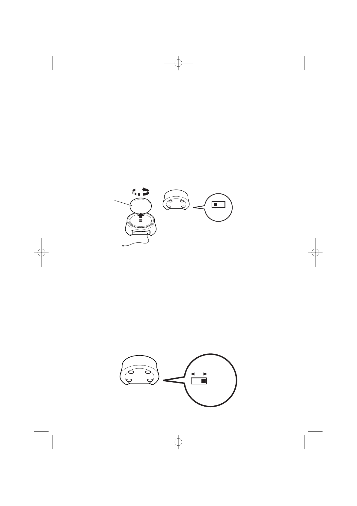
1. Switch on the transmitter (1) and the receiver (5) by switching their ON/OFF
buttons to the ON position.
2. Make sure that the transmitter and the receiver are set to the same
channel by checking the position of the selectors located under the
casing. They must be set to the same channel (same letter).
3. Switch on your equipment (television sets, video recorders ...) in both rooms.
4. Using the remote control of the unit whose pictures you wish to see, and from the
room containing the second television set (TV2), select the channels or video
functions (or others) according to the unit you are controlling.
Special operating details:
No pictur
e on TV2? If you fail to obtain the desired picture on the second television
set TV2, select the AV socket, to which the receiver (5) is connected, using the
television’s remote control.
Using a decoder (in France: Canal +, TPS, etc.) on your TV2
? To have clear
images on your second TV set (TV2), output from the decoder must pass through a
VCR player, placed in (AV2) mode or set to the channel number assigned for the
encrypted TV channel.
Use of a monitor
? If your second television set does not have a connection for an
outside aerial (terrestrial reception), or if it is a monitor, you will be able to see the
channels in the room containing the second television set by selecting those of the video
recorder with its remote control.
The pictur
e is scrambled? The running of certain equipment (micro-wave ovens,
digital telephone DECT, un-shielded acoustic loudspeakers, etc ...) may interfere with
signal transmission. Ensure that they are kept away from the transmitter and the
receiver or switch them off.
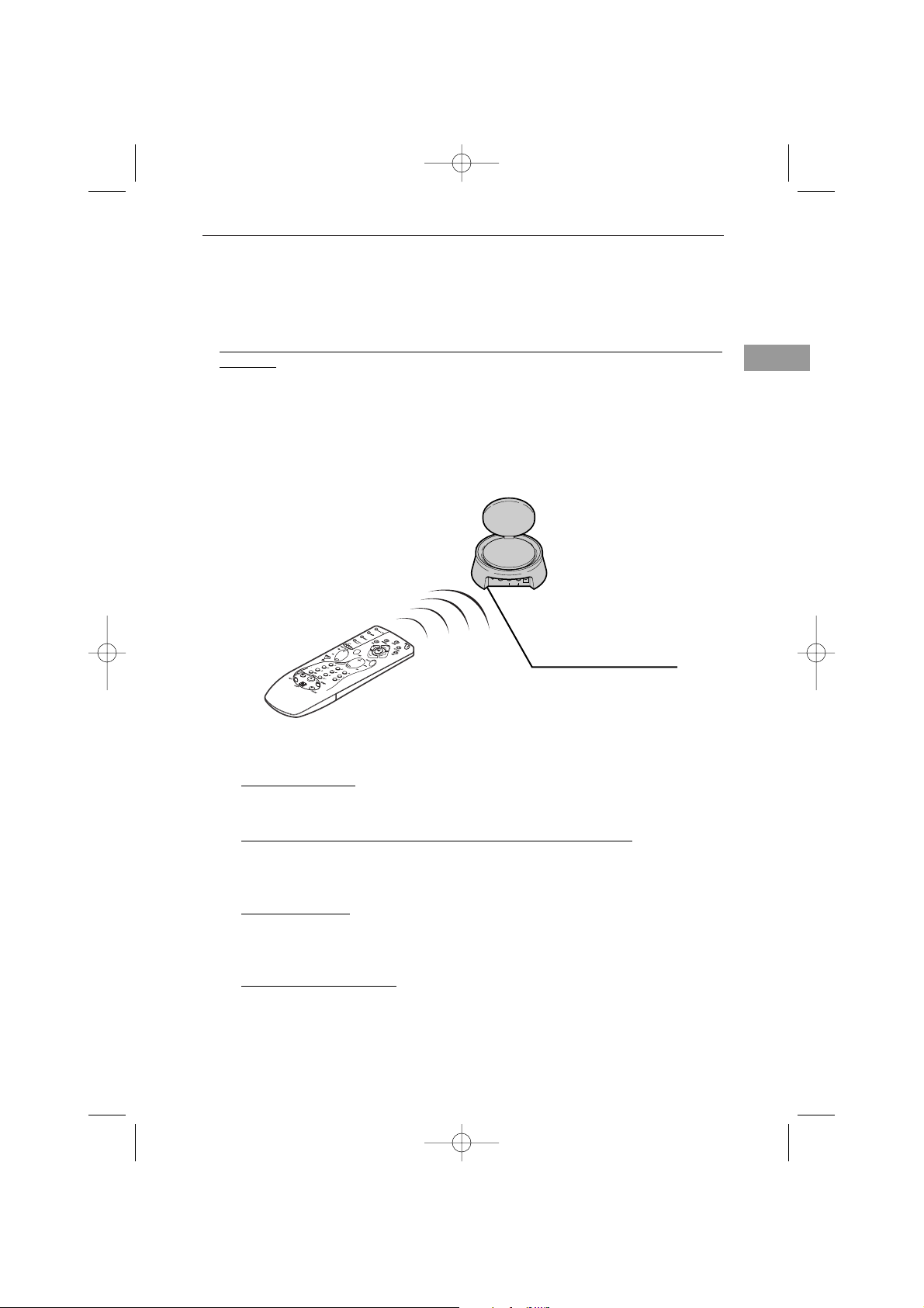
Make sure that you point the
remote control directly at the
receiver’s (5) infrared window
AUDIO IN DC 12VVIDEO INIR OUT
LEFT RIGHT
Receiver
Instructions for use
en
VS360/460 - 5 langues 12/02/03 10:45 Page 7
Page 8
8
You will obtain optimal service operation of your Video Sender by correctly
orienting the antennae (A). However, reflected signals or other signal degrading
factors can affect good quality signal transmission. In this case, readjust antennae
positions or slightly move the transmitter or receiver until you get crystal clear
reception.
If no picture is obtained,
check that the transmitter and the receiver have not been installed in the reverse
order (each unit corresponds either to the input or to the output of the Audio-Video
signal). Check that they have been properly connected and that they are switched on
(ON position). Ensure that the channel selector is set to the same letter on both units.
If transmission is blurred or scrambled,
choose another channel but make sure that it is identical on both units.
Improvement of picture and sound
AUDIO IN
DC 12V
VIDEO IN IR EXTENDLR
ON OFF
a, b, c, d
Transmitter / Receiver
Transmitter / Receiver
(A)
VS360/460 - 5 langues 12/02/03 10:45 Page 8
Page 9

9
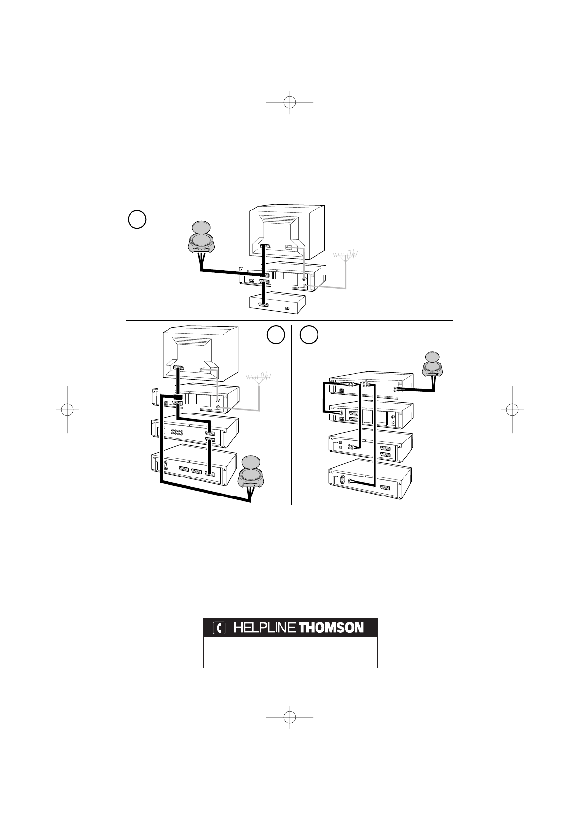
If you have several equipment items (VCR player, satellite receiver, DVD player, etc.)
in your main equipment room and want to transmit and receive audio and video
signals to a second TV set, connect your equipment items as shown in the Diagrams
on following pages. Usually, the units are connected in series, the last unit having a
free scart connection that you can use for the connection of the transmitter.
!
These diagrams represent some connection possibilities the operation of which depends on
the type of unit, its sockets and the signals it produces. There exist other connections that
you might perhaps wish to try if diagrams 1 to 3 here are not satisfactory. If this is the case,
ask your dealer for assistance.
!
As a general rule, remember to switch off units not in use. Also, refer to the manufacturers’
instructions to see if there are any particularities regarding connection or use. Certain units
may need to have their input scart connection “programmed”.
! I
n all cases the transmitter must be connected to a scart connection that produces an Audio-
Video signal Out. Refer to the manufacturer’s instructions for confirmation of this.
Relay of pictures from several units
en
VS360/460 - 5 langues 12/02/03 10:45 Page 9
Page 10
10
Technical characteristics
You can contact THOMSON by dialing: 0845 601 3093
(For Great-Britain, all calls will be charged at local rate)
www.thomson-europe.com
AUDIO IN DC 12VVIDEO INIR OUT
LEFT RIGHT
1
32
VCR
AV output
Audio amplifier
DVD
SAT
Transmitter
AUDIO IN DC 12VVIDEO INIR OUT
LEFT RIGHT
AUDIO IN DC 12VVIDEO INIR OUT
LEFT RIGHT
TV1
TV1
VCR
DVD
SAT
Transmitter
Satellite or Cable decoder
(Canal+, Canal Sat,TPS, Premiere,Telepiu, Via Digital…)
VCR
AV1
AV2
AUDIO
AV1
AV2
Transmitter
General information on connections...
Power supply: 12V DC
VS 360/460 : 4 channels (A : 2.411 GHz - B : 2.434 GHz - C : 2.454 GHz - D : 2.473 GHz)
VS 360U/460U : 4 channels (A : 2.411 GHz - B : 2.434 GHz - C : 2.454 GHz - D : 2.473 GHz)
VS 360SP/460SP : 3 channels (A : 2.421 GHz - B : 2.449 GHz - C : 2.477 GHz)
Remote control return: 433,92 MHz
Transmitter power: 10 mW
VS360/460 - 5 langues 12/02/03 10:45 Page 10
Page 11

1
Transmetteur vidéo sans fil
Précautions
• Sécurité
Les composants de cet appareil sont sensibles à la chaleur. La température maximale
ambiante ne doit pas dépasser 35° Celsius.
L’humidité des locaux où est placé l’appareil ne doit pas dépasser un taux
hygrométrique de 85 %. Evitez de l’exposer à l’eau de pluie ou aux éclaboussures.
Le passage d’une atmosphère froide à une ambiance chaude peut provoquer de la
condensation. Laissez-la disparaître d’elle-même avant de remettre l’appareil en
marche.
En cas d’absence prolongée, éteignez l’appareil avec l’interrupteur marche/arrêt.
Même à l’arrêt, certains composants restent en contact avec le réseau électrique. Pour
l’isoler complètement vous devez débrancher la fiche d’alimentation de la prise
secteur.
En cas d’orage, il est recommandé d’isoler l’appareil du réseau électrique afin de ne
pas le soumettre à des surcharges électriques ou électromagnétiques qui peuvent
l’endommager. A cette fin, laissez la fiche secteur accessible pour le débrancher.
Débranchez immédiatement l’appareil si vous constatez qu’il dégage une odeur de
brûlé ou de la fumée. En aucun cas vous ne devez ouvrir l’appareil vous-même,
vous risquez l’électrocution.
• Entretien
Nettoyez l’appareil avec un chiffon doux et un détergent neutre. L’utilisation de
solvants, de produits abrasifs ou de produits à base d’alcool risque d’endommager
l’appareil.
• Réglementation
Cet appareil ne doit être installé qu'à l'intérieur d'un local. Son utilisation est
restreinte aux transmissions radioélectriques privées. Le branchement à un réseau
public ou indépendant ou à une antenne extérieure est interdit.
Cet appareil ne doit en aucun cas être utilisé à des fins commerciales. Il est
uniquement prévu pour un usage domestique.
THOMSON dégage sa responsabilité en cas d’utilisation non conforme aux indications de
cette notice.
fr
VS360/460 - 5 langues 12/02/03 10:45 Page 1
Page 12

2
SALON CHAMBRE
Transmitter
(Emetteur)
Magnétoscope,
Récepteur satellite, ...
Receiver
(Récepteur)
Télécommande du
magnétoscope, récepteur
satellite... ou
télécommande universelle.
Principes de fonctionnement
VS360/460 - 5 langues 12/02/03 10:45 Page 2
Page 13
3
Le Video Sender VS 360/460 permet de diffuser un signal Audio-Video à partir de
votre installation principale vers un second téléviseur installé dans une autre pièce
et équipé d’une prise péritélévision (ou RCA/Cinch). L’installation principale est
l’endroit où vous avez regroupé la plupart de vos appareils (téléviseur,
magnétoscope, récepteur satellite, lecteur DVD, ...). Vous pourrez commander les
appareils depuis la pièce où se trouve le second téléviseur à l’aide de leurs
télécommandes, ou avec une télécommande universelle.
La diffusion de musique est possible si vous raccordez l’émetteur à une
source (
AUDIO OUT) et le récepteur à un amplificateur (AUDIO IN) dans une autre
pièce. Dans ce cas vous devrez vous procurer 1 câble cinch / cinch non fourni.
Si vous possédez un moniteur plasma ou un projecteur vidéo Thomson, le Video
Sender vous facilitera leur implantation à l’endroit désiré grâce à l’élimination des
problèmes liés à la longueur des câbles de connexions.
A quoi sert cet appareil ?
M
E
N
U
E
N
T
E
R
C
A
N
C
E
L
SE
LE
CT
PO
W
ER
STATUS
O
N
/
S
TA
ND
BY
S
OURC
E
AU
TO
A
D
JUS
T
PC
CA
RD
A
C
CESS
DVD
Moniteur plasma
TV
Magnétoscope
Camescope
Lecteur Video-disc
Récepteur et décodeur
Satellite/Câble
Vidéo projecteur
Amplificateur A/V
fr
VS360/460 - 5 langues 12/02/03 10:45 Page 3
Page 14

4
1. Placez l’émetteur (1) à proximité de l’appareil (magnétoscope, lecteur DVD…)
dont vous souhaitez diffuser les images et le son et raccordez-le à l’aide des deux
cordons (2 A et 2 B) en respectant les couleurs des 3 fiches cinch (rouge et blanche
pour l’audio, jaune pour la vidéo). Raccordez la fiche péritélévision à une prise du
magnétoscope ou du lecteur DVD (AV1).
Procurez-vous un cordon SCART-Péritélévision (non fourni) et raccordez le
téléviseur à l’adaptateur 2B déjà branché au magnétoscope ou lecteur DVD (voir
repère
*
de la page 5).
2. Déployez l’antenne de l’émetteur (1) avec précaution et orientez-la en direction de
la pièce du second téléviseur (TV2). Mettez en marche (position ON) l’émetteur et
le récepteur à l’aide du bouton ON/OFF situé en dessous et sur le coté. Placez le
sélecteur de canal de l’émetteur et du récepteur sur la même position (même
lettre).
3. Installez le cordon (4) en suivant ces étapes :
- raccordez la fiche jack dans la prise IR EXTEND,
- déroulez le cordon et placez une cellule à proximité de la fenêtre infrarouge de
l'appareil à commander,
- après l’installation du récepteur (voir page 6 et 7), demandez à une personne
d'utiliser la télécommande de l'appareil à commander depuis la pièce où se
trouve le second téléviseur (TV2),
- en déplaçant la cellule devant l'appareil à commander vous pourrez déterminer
l'emplacement qui permet sa commande depuis l'autre pièce. Vous devrez y
coller la cellule. Généralement il s'agit d'une zone transparente plus ou moins
grande située en façade.
4. Enlevez le papier de protection de la partie auto-collante de la cellule infrarouge
du cordon (4) et collez-la sur la fenêtre infrarouge de l’appareil à télécommander.
Le cordon est équipé de 3 cellules afin de vous permettre de diffuser les images et
le son de 3 appareils connectés au téléviseur (TV1) (voir schéma 2 de la page 10).
5. Branchez l’alimentation secteur (3) à l’émetteur et à une prise secteur 220/240V ~
50 Hz.
Installation de l’émetteur
VS360/460 - 5 langues 12/02/03 10:45 Page 4
Page 15
5
AUDIO IN DC 12VVIDEO INIR OUT
LEFT RIGHT
DC 12V
IR EXTEND
AV EXTEND
AUDIO IN
DC 12V
VIDEO IN IR EXTENDLR
AUDIO IN
DC 12V
VIDEO INIR EXTENDLR
2
1
3
4
220/240V ~ 50 Hz
TV1
TV2
*
A
B
fr
VS 360
VS 460
ROYAUME-UNI IRLANDE
EUROPE
CONTINENTALE
VS360/460 - 5 langues 12/02/03 10:45 Page 5
Page 16

6
AUDIO IN DC 12VVIDEO INIR OUT
LEFT RIGHT
R
e
c
e
i
v
e
r
Receiver
AUDIO OUT
LR
DC 12VVIDEO OUT
6
TV2
5
7
1. Placez le récepteur (5) sur, ou à proximité du second téléviseur.
2. Raccordez le récepteur (5) au second téléviseur à l’aide du cordon (6) en suivant
les mêmes recommandations que pour l’émetteur.
3. Déployez l’antenne du récepteur (5) et orientez-la en direction du téléviseur
principal (TV1).
4. Branchez l’alimentation secteur (7) au récepteur et à une prise secteur
220/240V ~ 50 Hz
.
! L’ANTENNE permet la diffusion du signal Audio-Video sur une portée maximum de
30 mètres en champ libre. A l’intérieur d’une habitation cette portée est inférieure et
dépend des matériaux que les ondes auront à franchir.
! L’ANTENNE SOUPLE permet la commande de l’appareil dont vous souhaitez voir les
images à partir de la pièce où se trouve le second téléviseur (TV2).
! L’ALIMENTATION de l’émetteur (1) possède une prise différente de celle de
l’alimentation du récepteur (7).
Installation du récepteur
220/240V ~ 50 Hz
ROYAUME-UNI
- IRLANDE
EUROPE
CONTINENTALE
VS360/460 - 5 langues 12/02/03 10:45 Page 6
Page 17

7
1. Mettez en marche l’émetteur (1) et le récepteur (5) en plaçant leurs boutons
ON/OFF sur la position ON.
2. Assurez-vous que l’émetteur et le récepteur soient bien sur le même
canal en vérifiant la position des sélecteurs sous leurs boîtiers. Ils
doivent être placés sur le même canal (même lettre).
3. Mettez en marche vos appareils (téléviseurs, magnétoscopes, ...) dans les 2 pièces.
4. A l’aide de la télécommande de l’appareil dont vous voulez voir les images, et de
la pièce où se trouve le second téléviseur (TV2), sélectionnez les chaînes ou les
fonctions de lecture (ou autres) selon l’appareil que vous commandez.
Quelques particularités de fonctionnement :
Pas d’image sur TV2
? Si vous n’obtenez pas l’image souhaitée sur le second
téléviseur TV2, sélectionnez la prise AV, à laquelle est raccordée le récepteur (5), à
l’aide de la télécommande du téléviseur.
Décodeur (Canal +, TPS…) sur TV2
? Pour être visible sur le second téléviseur
(TV2), l’image d’un décodeur doit passer par un magnétoscope, mis en marche, en
mode AV2 ou sur le n° de chaîne attribué à la chaîne codée. (Reportez-vous aux notices
des appareils correspondants).
Utilisation d’un moniteur
? Si votre second téléviseur ne possède pas de
raccordement à une antenne extérieure (réception hertzienne), ou si c’est un moniteur,
vous pourrez voir les chaînes en sélectionnant celles du magnétoscope, à partir de la
pièce du second téléviseur et à l’aide de la télécommande du magnétoscope.
L'image est br
ouillée ? Le fonctionnement de certains appareils (four à micro-ondes,
téléphone numérique DECT, enceintes acoustiques non blindées,etc ...) peut perturber
la transmission du signal. Veillez à les tenir éloignés de l'émetteur et du récepteur ou
éteignez-les.
Prenez soin de diriger la
télécommande vers la fenêtre
infrarouge du récepteur (5)
AUDIO IN DC 12VVIDEO INIR OUT
LEFT RIGHT
Receiver
(Récepteur)
Utilisation
fr
VS360/460 - 5 langues 12/02/03 10:45 Page 7
Page 18

8
Vous obtiendrez un fonctionnement optimal de votre Video Sender en orientant les
antennes (A). Toutefois, certaines réflexions ou autres effets parasites peuvent
affecter la bonne transmission du signal. Il suffira alors, soit de réajuster la position
des antennes soit de déplacer légèrement l'émetteur ou le récepteur jusqu’à
l’obtention d’une parfaite réception.
AUDIO IN
DC 12V
VIDEO IN IR EXTENDLR
ON OFF
Si vous n’obtenez aucune image,
vérifiez que l'émetteur et le récepteur n’aient pas été inversés (chaque boîtier
correspond soit à l’entrée soit à la sortie du signal Audio-Video). Vérifiez qu’ils sont
bien connectés et en marche (position ON). Assurez-vous que le sélecteur des canaux
est bien positionné sur la même lettre.
Si la transmission n’est pas claire ou brouillée,
choisissez un autre canal en veillant à ce qu’ils soient identiques sur les 2 boîtiers.
a, b, c, d
Transmitter / Receiver
(Emetteur) / (Récepteur)
Transmitter / Receiver
(Emetteur) / (Récepteur)
(A)
Amélioration de l’image et du son
VS360/460 - 5 langues 12/02/03 10:45 Page 8
Page 19

9
Si dans votre installation principale, vous possédez plusieurs appareils
(magnétoscope, récepteur satellite, lecteur DVD...) dont vous souhaitez diffuser les
images et le son vers un second téléviseur, raccordez-les en suivant les indications
des schémas proposés en page suivante. En général les appareils sont raccordés en
série, le dernier appareil disposant d’une prise péritélévision de libre que vous
pourrez utiliser pour raccorder l’émetteur.
!
Ces schémas représentent quelques possibilités de raccordements dont le fonctionnement
dépend des appareils, de leurs prises et des signaux qu’ils fournissent. Il existe donc d’autres
raccordements que vous serez peut-être amenés à essayer si les schémas 1 à 3 proposés ne
vous satisfont pas. Dans ce cas faites-vous aider par votre revendeur.
!
De façon générale, pensez à éteindre les appareils non utilisés. Consultez également les
notices des constructeurs pour connaître d’éventuelles particularités de branchement ou
d’utilisation. Certains appareils peuvent nécessiter une “programmation” de la prise
péritélévision du signal entrant.
!
Dans tous les cas l’émetteur doit être branché sur une prise péritélévision fournissant un
signal Audio-V
ideo Out. Reportez-vous à la notice du constructeur pour le vérifier.
Diffusion des images de plusieurs
appareils
fr
VS360/460 - 5 langues 12/02/03 10:45 Page 9
Page 20

10
Caractéristiques techniques
Alimentation : 12V DC
VS 360/460 : 4 canaux (A : 2.411 GHz - B : 2.434 GHz - C : 2.454 GHz - D : 2.473 GHz)
VS 360U/460U : 4 canaux (A : 2.411 GHz - B : 2.434 GHz - C : 2.454 GHz - D : 2.473 GHz)
VS 360SP/460SP : 3 canaux (A : 2.421 GHz - B : 2.449 GHz - C : 2.477 GHz)
Retour télécommande : 433,92 MHz
Puissance de l’émetteur : 10 mW
Votre contact THOMSON : 0 810 810 891
(Pour la France, prix d’un appel local)
www.thomson-europe.com
AUDIO IN DC 12VVIDEO INIR OUT
LEFT RIGHT
1
32
VCR
Sortie AV
Amplificateur Audio
DVD
SAT
Transmitter
(Emetteur)
AUDIO IN DC 12VVIDEO INIR OUT
LEFT RIGHT
AUDIO IN DC 12VVIDEO INIR OUT
LEFT RIGHT
TV1
TV1
VCR
DVD
SAT
Transmitter
(Emetteur)
Décodeur satellite / câble
(Canal+, Canal Sat,TPS, Premiere,Telepiu, Via Digital…)
VCR
AV1
AV2
AUDIO
AV1
AV2
Transmitter
(Emetteur)
A propos des raccordements …
VS360/460 - 5 langues 12/02/03 10:45 Page 10
Page 21

1
Video-Signal-Sender/-Empfänger
Vorsichtsmaßnahmen
• Sicherheit
Die Bauteile dieses Geräts sind wärmeempfindlich. Die maximale
Umgebungstemperatur darf 35 °C nicht überschreiten.
Die Luftfeuchtigkeit im Aufstellungsraum des Geräts darf einen
Feuchtigkeitsgehalt von 85% nicht übersteigen. Sollten Sie Ihr Gerät im Freien
betreiben, schützen Sie es unbedingt vor Regen und Spritzwasser. Der Transport des
Geräts aus einer kalten Umgebung in einen warmen Raum kann Kondensation
hervorrufen. Warten Sie, bis diese von allein abtrocknet, bevor Sie das Gerät in
Betrieb nehmen.
Bei längerer Abwesenheit das Gerät mit dem Netzschalter abschalten. Selbst wenn
der Netzschalter sich in der Aus-Stellung befindet, ist das Gerät nicht vollständig
vom Netz getrennt. Um das Gerät vollständig stromlos zu machen, muß der
Netzstecker gezogen werden.
Bei Gewitter wird empfohlen, das Gerät vom Netz zu trennen, damit es nicht
elektrischen bzw. elektromagnetischen Einwirkungen ausgesetzt wird, die es
beschädigen können. Deshalb muß der Netzstecker stets zugänglich sein, damit Sie
ihn jederzeit aus der Steckdose ziehen können.
Sofort den Netzstecker ziehen, wenn Sie bemerken, daß das Gerät einen
Verbrennungsgeruch oder Rauch verströmt. Öffnen Sie das Gerät auf keinen Fall
selbst, Sie setzen sich sonst der Gefahr lebensgefährlicher elektrischer Schläge aus.
• Pflege
Das Gerät mit einem weichen Lappen und einem neutralen Putzmittel reinigen.
Verwenden Sie keine Lösungsmittel, Scheuermittel und Reinigungsmittel auf
Alkoholbasis, da diese Ihr Gerät beschädigen könnten.
• Gesetzliche Vorschriften
Dieses Gerät ist zum Betrieb in geschlossenen Räumen bestimmt. Seine Benutzung
ist auf die private Funkübertragung beschränkt. Der Anschluß an ein öffentliches
bzw. privates Netz oder an eine Außenantenne ist untersagt.
Dieses Gerät darf auf keinen Fall zu gewerblichen Zwecken verwendet werden,
sondern dient ausschließlich dem Heimgebrauch.
Der nichtbestimmungsgemäße Gebrauch bzw. die Nichtbeachtung der Anweisungen dieser
Bedienungsanleitung erfolgt auf eigene Gefahr, unter Ausschluß aller Rechtsansprüche
gegenüber THOMSON.
de
VS360/460 - 5 langues 12/02/03 10:45 Page 1
Page 22

2
WOHNZIMMER SCHLAFZIMMER
Transmitter
(Sender)
Videorecorder,
Satellitenempfänger usw.
Receiver
(Empfänger)
Fernbedienung des
Videorecorders,
Satellitenempfängers
usw. – oder
Universalfernbedienung.
Funktionsprinzipien
VS360/460 - 5 langues 12/02/03 10:45 Page 2
Page 23

3
Der Video Sender VS 360/460 erlaubt die Übertragung eines Audio-Video-Signals über
Ihre Hauptanlage an einen zweiten, in einem anderen Raum aufgestellten und mit
einer SCART-Buchse (oder RCA/Cinch) ausgestatteten Fernseher. Die Hauptanlage
befindet sich dort, wo Sie den größten Teil Ihrer Geräte (Fernseher, Videorecorder,
Satellitenempfänger, DVD-Spieler usw.) aufgestellt haben. Sie können diese Geräte
vom Raus aus, in dem sich der Zweitfernseher befindet, steuern, entweder mit den
Fernbedienungen Ihrer Geräte, oder mit einer Universalfernbedienung.
Die Musikübertragung ist möglich, wenn Sie den Sender an eine Quelle (
AUDIO OUT)
und den Empfänger an einen Verstärker (
AUDIO IN) in einem anderen Raum
anschließen. In diesem Fall müssen Sie sich ein Kabel cinch / cinch (nicht
mitgeliefert) beschaffen.
Wenn Sie einen Plasma-Bildschirm oder einen Thomson-Videoprojektor besitzen,
erleichtert der Video Sender Ihnen deren Aufstellung am gewünschten Ort, denn es
gibt keine durch lange Anschlusskabel hervorgerufene Probleme.
Wozu dient dieses Gerät?
M
E
N
U
E
N
T
E
R
C
A
N
C
E
L
SE
LE
CT
PO
W
ER
STATUS
O
N
/
S
TA
ND
BY
S
OURC
E
AU
TO
A
D
JUS
T
PC
CA
RD
A
C
CESS
DVD-Spieler
Plasma-Bildschirm
Fernseher
Videorecorder
Camcorder
Video-disc-Spieler
Satelliten- und
Kabelempfänger / -decoder
Videoprojektor
A-V-Verstärker
de
VS360/460 - 5 langues 12/02/03 10:45 Page 3
Page 24

4
1. Sender (1) in der Nähe des Gerätes (Videorecorder, DVD-Player…), dessen Bilder
und Ton Sie übertragen wollen, anordnen und mit Hilfe der beiden Schnüre (2 A
und 2 B) anschließen, indem Sie die Farben der 3 Cinch-Stecker beachten (rot und
weiß für Audio, gelb für Video). Peritelevision-Stecker an eine Buchse des
Videorecorders oder des DVD-Players (AV1) anschließen.
Beschaffen Sie sich eine SCART-Peritelevision-Anschlussschnur (nicht
mitgeliefert) und schließen das Fernsehgerät an den bereits an den Videorecorder
oder den DVD-Player angeschlossenen Adapter 2B an (siehe Markierung
*
auf
Seite 5).
2. Antenne des Senders (1) vorsichtig ausfahren und auf den Raum ausrichten, in
dem sich das zweite Fernsehgerät (TV2) befindet. Sender und Empfänger mit dem
unten und seitlich befindlichen Schaltknopf ON/OFF einschalten. Kanalwähler
des Senders und Empfängers in die gleiche Position stellen (gleicher Buchstabe).
3. Zum Anschließen des Kabels (4) die folgenden Schritte ausführen:
- Den Klinkenstecker in die Buchse IR EXTEND stecken,
- Das Kabel abwickeln und eine Zelle in der Nähe des Infrarotfensters des zu
steuernden Geräts (Videorecorder oder anderes Gerät) positionieren.
- Nach Installation des Empfängers (siehe Seiten 6 und 7) eine Person bitten, die
Fernbedienung des zu bedienenden Gerätes von dem Raum aus, in dem sich das
zweite Fernsehgerät (TV2) befindet, zu betätigen.
- Durch Verschieben der Zelle vor dem zu steuernden Gerät können Sie den
Anbringungsort bestimmen, der das Steuern vom anderen Raum aus erlaubt.
Kleben Sie die Zelle an der ermittelten günstigsten Stelle an. Es handelt sich in
der Regel um einen mehr oder weniger großen durchsichtigen Bereich auf der
Vo rderseite.
4. Schutzpapier des Selbstklebeteils der Infrarotzelle der Schnur (4) entfernen und
auf das Infrarotfenster des fernzubedienenden Geräts kleben. Die Schnur ist mit
drei Zellen ausgestattet, um es Ihnen zu gestatten, Bilder und Ton von drei an das
Fernsehgerät (TV1) angeschlossenen Geräten zu übertragen (siehe Schema 2 auf
Seite 10).
5. Das Netzgerät (3) an den Sender und an eine Netzsteckdose (220/240V ~ 50 Hz)
anschließen.
Inbetriebnahme des Senders
VS360/460 - 5 langues 12/02/03 10:45 Page 4
Page 25

5
de
AUDIO IN DC 12VVIDEO INIR OUT
LEFT RIGHT
DC 12V
IR EXTEND
AV EXTEND
AUDIO IN
DC 12V
VIDEO IN IR EXTENDLR
AUDIO IN
DC 12V
VIDEO INIR EXTENDLR
2
1
3
4
220/240V ~ 50 Hz
TV1
*
A
B
VS 360
VS 460
GROßBRITANNIEN
- IRLAND
KONTINENTALEUROPA
VS360/460 - 5 langues 12/02/03 10:45 Page 5
Page 26

6
1. Den Empfänger (5) auf dem bzw. in der Nähe des zweiten Fernsehers aufstellen.
2. Den Empfänger (5) mit dem Kabel (6) an den zweiten Fernseher anschließen,
indem Sie nach den selben Anweisungen wie für den Sender vorgehen.
3. Antenne des Empfängers (5) ausfahren und auf das Hauptfernsehgerät (TV1)
richten.
4. Das Netzgerät (7) an den Sender sowie an eine Netzsteckdose (220/240V ~ 50 Hz)
anschließen.
! DIE ANTENNE ermöglicht die Übertragung des Audio/Video-Signals über eine
maximale Reichweite von 30 Metern im freien Feld. Innerhalb eines Wohnhauses ist
diese Reichweite geringer und hängt von den Baustoffen ab, welche die Wellen zu
durchdringen haben.
! DIE FLEXIBLE ANTENNE dient zur Steuerung des Geräts, dessen Bilder Sie im
Aufstellungsraum des zweiten Fernsehers (TV2) betrachten möchten.
! DAS NETZGERÄT des Senders (1) ist mit einer anderen Buchse als das Netzgerät des
Empfängers (7) ausgestattet.
Inbetriebnahme des Empfängers
AUDIO IN DC 12VVIDEO INIR OUT
LEFT RIGHT
R
e
c
e
i
v
e
r
Receiver
AUDIO OUT
LR
DC 12VVIDEO OUT
6
TV2
5
7
220/240V ~ 50 Hz
GROßBRITANNIEN
- IRLAND
KONTINENTAL
-EUROPA
VS360/460 - 5 langues 12/02/03 10:45 Page 6
Page 27

7
1. Den Sender (1) und den Empfänger (5) einschalten, indem Sie deren ON/OFF-
Schalter auf ON schalten.
2. V
ergewissern Sie sich, daß Sender und Empfänger auf den selben
Kanal eingestellt sind, indem Sie die Stellung der an den
Gehäuseunterseiten angebrachten Wahlschalter überprüfen. Beide
Wahlschalter müssen auf den selben Kanal eingestellt sein (d.h. auf
den selben Buchstaben).
3. Schalten Sie Ihre Geräte (Fernseher, Videorecorder usw.) in den beiden Räumen ein.
4. Im Aufstellungsraum des zweiten Fernsehers (TV2) mit der Fernbedienung des
Geräts, dessen Bilder Sie sehen möchten, das gewünschte Programm bzw. die
Wiedergabefunktion (oder eine andere Funktion) wählen bzw. aktivieren, je nach
dem zu steuernden Gerät.
Einige Besonderheiten des Betriebs:
TV2 hat kein Bild
?Wenn das gewünschte Bild nicht vom zweiten Fernseher TV2
angezeigt wird, müssen Sie die AV-Buchse, an die der Empfänger (5) angeschlossen
ist, mit der Fernbedienung des Fernsehgeräts wählen.
Decoder (Canal +, TPS…) an TV2
? Damit es auf dem zweiten Fernseher (TV2)
sichtbar ist, muss das Bild eines Decoders über einen Videorecorder, der im Modus
AV2 eingeschaltet ist, oder über das dem codierten Programm zugeordneten
Programm gehen.
Einsatz eines Monitors
?Wenn Ihr zweiter Fernseher nicht an eine Außenantenne
(Funkfernsehempfang) angeschlossen ist oder wenn es sich um einen Monitor handelt,
können Sie die Fernsehprogramme sehen, indem Sie im Ausstellungsraum des zweiten
Fernsehers bzw. Monitors die vom Videorecorder empfangenen Programme mit dessen
Fernbedienung wählen.
Bildstörungen
? Der Betrieb einiger Geräte (Mikrowellengerät, DECT-Digitaltelefon,
nicht abgeschirmte Lautsprecherboxen usw.) kann die Signalübertragung stören.
Denken Sie daran, diese Geräte in möglichst großer Entfernung vom Sender und
Empfänger aufzustellen oder auszuschalten.
Denken Sie daran, die
Fernbedienung stets auf das
Infrarotfenster des Empfängers
(5) zu richten
AUDIO IN DC 12VVIDEO INIR OUT
LEFT RIGHT
Receiver
(Empfänger)
Benutzung
de
VS360/460 - 5 langues 12/02/03 10:45 Page 7
Page 28

8
Ihr Video-Sender funktioniert optimal, wenn Sie die Antennen (A) richtig
ausrichten. Gewisse Reflexionen oder sonstige Störeffekte können jedoch die gute
Übertragung des Signals beeinträchtigen. In diesem Fall genügt es, entweder die
Antennen neu auszurichten oder den Sender oder Empfänger leicht zu verschieben,
um einen guten Empfang zu erhalten.
Sie haben überhaupt kein Bild,
Ve rgewissern Sie sich, daß Sender und Empfänger nicht vertauscht sind (jedes Gerät
entspricht entweder dem Audio-Video-Signaleingang oder -ausgang). Prüfen Sie, ob
die Geräte richtig angeschlossen und eingeschaltet sind (Schalter auf ON). Stellen
Sie sicher, daß beide Kanalwählschalter auf den selben Buchstaben gestellt sind.
Bei schlechter Übertragungsqualität bzw. gestörtem Bild,
Einen anderen Kanal wählen und dabei darauf achten, daß an beiden Geräten der
selbe Kanal eingestellt wird.
Verbessern von Bild und Tone
AUDIO IN
DC 12V
VIDEO IN IR EXTENDLR
ON OFF
a, b, c, d
Transmitter / Receiver
( Sender) / ( Empfänger)
Transmitter / Receiver
( Sender) / ( Empfänger)
(A)
VS360/460 - 5 langues 12/02/03 10:45 Page 8
Page 29

9
Wenn Sie in Ihrer Hauptanlage mehrere Geräte (Videorecorder, Satellitenempfänger,
DVD-Player…) besitzen, deren Bilder und Ton Sie auf einen zweiten Fernseher
übertragen wollen, schließen Sie diese gemäß den Angaben der auf folgender Seite
abgebildeten Schemata an. Die Geräte werden in der Regel in Serie geschaltet, wobei
das letzte Gerät über eine freie Scart-Buchse verfügen muß, an die Sie Ihren Sender
anschließen.
! Auf diesen Anschlußplänen werden einige Anschlußmöglichkeiten dargestellt, deren
Funktionieren von den Geräten und deren Buchsen und Ausgangssignalen abhängt.
Es bestehen jedoch noch weitere Anschlußmöglichkeiten, welche Sie vielleicht
ausprobieren müssen, falls Sie die in den Plänen 1-3 vorgeschlagenen Lösungen nicht
befriedigen. In diesem Fall sollten Sie sich von Ihrem Fachhändler helfen lassen.
!
Denken Sie stets daran, die nicht benutzten Geräte auszuschalten. Schlagen Sie ebenfalls
in den Bedienungsanleitungen der Hersteller nach, um sich über eventuelle Besonderheiten
hinsichtlich der Anschlüsse oder des Betriebs zu informieren. Einige Geräte erfordern eine
“Programmierung“ der Scart-Buchse auf das Eingangssignal.
!
Der Sender muß immer an eine ein Audio-V
ideo-Signal Out liefernde Scart-Buchse
angeschlossen werden. Schlagen Sie in der Bedienungsanleitung des Herstellers nach, um
diesen Punkt zu überprüfen.
Übertragung der Bilder von
mehreren Geräten
de
VS360/460 - 5 langues 12/02/03 10:45 Page 9
Page 30

10
AUDIO IN DC 12VVIDEO INIR OUT
LEFT RIGHT
1
32
VCR
AV-Ausgang
Audio-Verstärker
DVD
SAT
Transmitter
(Sender)
AUDIO IN DC 12VVIDEO INIR OUT
LEFT RIGHT
AUDIO IN DC 12VVIDEO INIR OUT
LEFT RIGHT
TV1
TV1
VCR
DVD
SAT
Transmitter
(Sender)
Satelliten- oder Kabelempfänger/decoder
(Canal+, Canal Sat,TPS, Premiere,Telepiu, Via Digital…)
VCR
AV1
AV2
AUDIO
AV1
AV2
Transmitter
(Sender)
Apropos Anschlüsse…
Technische Daten
Ihr Kontakt zu THOMSON: 0180 1000 390
(Für Deutschland, Kosten zum Ortstarif.)
www.thomson-europe.com
Versorgungsspannung: 12V DC
VS 360/460 : 4 Kanäle (A : 2.411 GHz - B : 2.434 GHz - C : 2.454 GHz - D : 2.473 GHz)
VS 360U/460U : 4 Kanäle (A : 2.411 GHz - B : 2.434 GHz - C : 2.454 GHz - D : 2.473 GHz)
VS 360SP/460SP : 3 Kanäle (A : 2.421 GHz - B : 2.449 GHz - C : 2.477 GHz)
Weiterleitungsfrequenz: 433,92 MHz
Sendeleistung: 10 mW
VS360/460 - 5 langues 12/02/03 10:45 Page 10
Page 31

1
Video sender senza fili
Precauzioni
• Sicurezza
I vari elementi che compongono quest’apparecchio sono sensibili al calore. La
temperatura massima ambiente non deve oltrepassare i 35° Celsius.
L’umidità dei locali in cui si trova l’apparecchio non deve oltrepassare un tasso
igrometrico dell’85%. Se dovete utilizzare l’apparecchio all’aperto, evitate di esporlo
alla pioggia o a schizzi d’acqua. Il passaggio da un’atmosfera fredda ad un ambiente
caldo può provocare l’apparizione di condensa. Lasciatela sparire da sola prima di
rimettere in funzione l’apparecchio.
In caso di assenza prolungata, spegnete l’apparecchio con l’interruttore
acceso/spento. Anche se l’apparecchio è spento, alcuni elementi restano sempre in
contatto con la rete elettrica. Per isolarlo completamente dovete staccare la spina di
alimentazione dalla presa della rete elettrica.
In caso di temporale, si raccomanda di isolare l’apparecchio dalla rete elettrica per
non sottoporlo a sovraccarichi elettrici o elettromagnetici che possono danneggiarlo.
A questo scopo, lasciate la spina della rete elettrica ben accessibile per poter staccare
l’apparecchio dalla corrente.
Staccate immediatamente l’apparecchio dalla corrente se constatate che emana fumo
o odore di bruciato. Non dovete in nessun caso aprirlo da soli, rischiereste di restare
fulminati.
• Manutenzione
Pulite l’apparecchio con un panno morbido ed un detergente neutro. L’uso di
solventi, di prodotti abrasivi o a base di alcol rischia di danneggiare l’apparecchio.
• Normativa
Questo apparecchio deve essere installato solo all’interno di un locale. La sua
utilizzazione è limitata alle trasmissioni radioelettriche private. Il collegamento ad
una rete pubblica o indipendente o ad un’antenna esterna è vietato.
Questo apparecchio non deve in alcun modo essere utilizzato a fini industriali.
E’ previsto soltanto per un uso domestico.
THOMSON declina ogni responsabilità in caso di utilizzazione non conforme a quanto
indicato in questo libretto.
it
VS360/460 - 5 langues 12/02/03 10:45 Page 1
Page 32

2
SALOTTO CAMERA
Transmitter
(Emettitore)
Videoregistratore,
ricevitore via satellite, ...
Receiver
(Ricevitore)
Telecomando del
videoregistratore,
ricevitore via satellite, ...
o telecomando
universale.
Principi di funzionamento
VS360/460 - 5 langues 12/02/03 10:45 Page 2
Page 33

3
Il Video Sender VS 360/460 permette di diffondere un segnale Audio-Video a partire
dal vostro impianto principale verso un secondo televisore installato in un’altra
stanza ed equipaggiato di una presa SCART (o RCA/Cinch). L’impianto principale
è il punto dove avete riunito la maggior parte dei vostri apparecchi (televisore,
videoregistratore, ricevitore via satellite, lettore DVD, ...). Potrete comandare gli
apparecchi dalla stanza dove si trova il secondo televisore servendovi dei loro
telecomandi o con un telecomando universale.
La diffusione di musica è possibile se si collega l’emettitore a una fonte (
AUDIO OUT)
e il ricevitore a un amplificatore (
AUDIO IN) in un’altra stanza. In questo caso, occorre
procurarsi 1 cavo cinch / cinch (non fornito).
Se si possiede un monitor al plasma o un videoproiettore Thomson, il Video Sender
ne faciliterà l’installazione nel luogo desiderato grazie all’eliminazione dei problemi
legati alla lunghezza dei cavi di connessione.
A che cosa serve questo apparecchio?
M
E
N
U
E
N
T
E
R
C
A
N
C
E
L
SE
LE
CT
PO
W
ER
STATUS
O
N
/
S
TA
ND
BY
S
OURC
E
AU
TO
A
D
JUS
T
PC
CA
RD
A
C
CESS
Lettore di DVD
Monitor al plasma
Televisore
Videoregistratore
Videocamera
Lettore di Video-disc
Ricevitore e decodificatore
Satellite/Cavo
Videoproiettore
Amplificatore A/V
it
VS360/460 - 5 langues 12/02/03 10:45 Page 3
Page 34

4
1. Collocare l’emettitore (1) in prossimità dell’apparecchio (videoregistratore,
lettore DVD…) di cui si desiderano diffondere le immagini e il suono e
collegarlo mediante i due cordoni (2 A e 2 B) rispettando i colori delle 3 spine
cinch (rosso e bianco per l’audio, giallo per il video). Collegare la spina peritel a
una presa del videoregistratore o del lettore DVD (AV1).
Procurarsi un cavo SCART-Peritel (non fornito) e collegare il televisore
all’adattatore 2B già collegato al videoregistratore o lettore DVD (cfr. il simbolo
*
della pagina 5).
2. Spiegare l’antenna dell’emettitore (1) con precauzione e orientarla in direzione
della stanza del secondo televisore (TV2). Accendere (posizione ON) l’emettitore
e il ricevitore mediante il pulsante ON/OFF situato al di sotto e sul lato. Collocare
il selettore di canale dell’emettitore e del ricevitore sulla stessa posizione (stessa
lettera).
3. Installate il cavo (4) rispettando le seguenti tappe:
- collegate la spina jack nella presa IR EXTEND,
- svolgete il cavo e mettete una cellula nelle vicinanze della finestra ad infrarossi
dell’apparecchio da comandare (videoregistratore o altro),
- dopo l’installazione del ricevitore (vedere pagine 6 e 7), chiedere a una persona
di utilizzare il telecomando dell’apparecchio da comandare dalla stanza in cui si
trova il secondo televisore (TV2),
- spostando la cellula davanti all’apparecchio da comandare potrete determinare il
punto che permette di comandarlo partendo dall’altra stanza. Dovrete incollarvi
la cellula. Di solito si tratta di una zona trasparente più o meno grande situata
sulla faccia avanti.
4. Rimuovere la carta protettiva dalla parte autoadesiva della cellula infrarossa del
cordone (4) e incollarla sulla finestra infrarossa dell’apparecchio da
telecomandare. Il cordone è munito di 3 cellule per consentire la diffusione delle
immagini e del suono di 3 apparecchi collegati al televisore (TV1) (vedere schema
2 della pagina 10).
5. Collegate l’alimentazione rete elettrica (3) all’emittente e ad una presa rete elettrica
220/240 V ~ 50 Hz.
Installazione dell’emittente
VS360/460 - 5 langues 12/02/03 10:45 Page 4
Page 35

5
it
AUDIO IN DC 12VVIDEO INIR OUT
LEFT RIGHT
DC 12V
IR EXTEND
AV EXTEND
AUDIO IN
DC 12V
VIDEO IN IR EXTENDLR
AUDIO IN
DC 12V
VIDEO INIR EXTENDLR
2
1
3
4
220/240V ~ 50 Hz
TV1
*
A
B
VS 360
VS 460
GRAN
BRETAGNA IRLANDA
EUROPA
CONTINENTALE
VS360/460 - 5 langues 12/02/03 10:45 Page 5
Page 36

6
1. Posizionate il ricevitore (5) su o nelle vicinanze del secondo televisore.
2. Collegate il ricevitore (5) al secondo televisore mediante il cavo (6) seguendo le
stesse raccomandazioni fatte per l’emittente.
3. Spiegare l’antenna del ricevitore (5) e orientarla in direzione del televisore
principale (TV1).
4. Collegate l’alimentazione rete elettrica (7) al ricevitore e ad una presa rete
elettrica 220/240 V ~ 50 Hz.
! L’ANTENNA consente la diffusione del segnale Audio-Video su una portata massima
di 30 metri in campo libero. All’interno di un’abitazione, questa portata è inferiore e
dipende dai materiali che le onde dovranno attraversare.
! L’ANTENNA FLESSIBILE permette di comandare l’apparecchio del quale desiderate
vedere le immagini a partire dalla stanza in cui si trova il secondo televisore (TV2).
! L’ALIMENTAZIONE dell’emittente (1) possiede una presa diversa da quella
dell’alimentazione del ricevitore (7).
Installazione del ricevitore
AUDIO IN DC 12VVIDEO INIR OUT
LEFT RIGHT
R
e
c
e
i
v
e
r
Receiver
AUDIO OUT
LR
DC 12VVIDEO OUT
6
TV2
5
7
220/240V ~ 50 Hz
GRAN
BRETAGNA IRLANDA
EUROPA
CONTINENTALE
VS360/460 - 5 langues 12/02/03 10:45 Page 6
Page 37

7
1. Mettete in funzione l’emittente (1) ed il ricevitore (5) mettendo i loro pulsanti
ON/OFF in posizione ON.
2. V
erificate che l’emittente ed il ricevitore sono sullo stesso canale
verificando la posizione dei selettori sotto le loro scatole. Devono
trovarsi sullo stesso canale (stessa lettera).
3. Mettete in funzione i vostri apparecchi (televisori, videoregistratore,...) nelle 2
stanze.
4. Mediante il telecomando dell’apparecchio di cui desiderate vedere le immagini e
dalla stanza dove si trova il secondo televisore (TV2) selezionate i canali o le
funzioni di lettura (o altre) secondo l’apparecchio che comandate.
Qualche particolarità di funzionamento:
Non ci sono immagini sul TV2
? Se non ottenete l’immagine voluta sul secondo
televisore TV2, selezionate la presa AV alla quale è collegato il ricevitore (5) mediante
il telecomando del televisore.
Decoder (T
ele+, Canal +, TPS…) su TV2? Per essere visibile sul secondo televisore
(TV2), l’immagine di un decoder deve passare per un videoregistratore, acceso, in
modalità AV2 o sul n° di canale attribuito al canale codificato.
Utilizzazione di uno schermo
? Se il vostro secondo televisore non possiede
collegamento ad un’antenna esterna (ricezione hertziana) o se è un semplice schermo,
potrete vedere i canali selezionando quelli del videoregistratore, dalla stanza del
secondo televisore e mediante il telecomando del videoregistratore.
L
’immagine è disturbata
? Il funzionamento di alcuni apparecchi (forno a microonde, telefono digitale DECT, altoparlanti non schermati ecc...) può disturbare la
trasmissione del segnale. Teneteli lontani dall’emittente e dal ricevitore o spegneteli.
Abbiate cura di dirigere il
telecomando verso la finestra
ad infrarossi del ricevitore (5)
AUDIO IN DC 12VVIDEO INIR OUT
LEFT RIGHT
Receiver
(Ricevitore)
Utilizzazione
it
VS360/460 - 5 langues 12/02/03 10:45 Page 7
Page 38

8
Si otterrà un funzionamento ottimale del Video Sender orientando le antenne (A).
Tuttavia, alcune riflessioni o altri effetti parassiti possono influire sulla buona
trasmissione del segnale. Basterà, allora, regolare nuovamente la posizione delle
antenne, oppure spostare leggermente l’emettitore fino all’ottenimento di una
ricezione perfetta.
Se non ottenete nessuna immagine,
verificate che l’emittente ed il ricevitore non siano stati invertiti (ogni scatola
corrisponde sia all’entrata sia all’uscita del segnale Audio/Video). Verificate che
sono ben collegati ed in funzione (posizione ON). Verificate che il selettore dei canali
è posizionato sulla stessa lettera.
Se la trasmissione non è chiara o è disturbata,
scegliete un altro canale facendo attenzione a che siano identici sulle due scatole.
Miglioramento dell’immagine e del
suono
AUDIO IN
DC 12V
VIDEO IN IR EXTENDLR
ON OFF
a, b, c, d
Transmitter / Receiver
( Emettitore) / ( Ricevitore)
Transmitter / Receiver
( Emettitore) / ( Ricevitore)
(A)
VS360/460 - 5 langues 12/02/03 10:45 Page 8
Page 39

9
Se nell’impianto principale si possiedono più apparecchi (videoregistratore,
ricevitore satellite, lettore DVD...) di cui si desidera diffondere le immagini e il suono
verso un secondo televisore, collegarli seguendo le indicazioni degli schemi proposti
alla pagina seguente. In genere gli apparecchi sono collegati in serie, e l’ultimo
dispone di una presa scart libera che potrete utilizzare per collegare l’emittente.
!
Questi schemi rappresentano alcune possibilità di collegamento il cui funzionamento
dipende dai vostri apparecchi, dalle prese e dai segnali che forniscono. Esistono altri
collegamenti che dovrete forse provare se gli schemi da 1 a 3 proposti non vi soddisfano. In
questi casi, fatevi aiutare dal vostro rivenditore.
!
In linea generale, pensate a spegnere gli apparecchi non utilizzati. Consultate anche le
istruzioni dei fabbricanti per sapere le particolarità eventuali di collegamento o di
utilizzazione. Alcuni apparecchi possono richiedere una “programmazione” della presa
scart del segnale in entrata.
!
In tutti i casi l’emittente deve essere collegata su una presa scart che fornisce un segnale
Audio-Video Out. Fate riferimento alle istruzioni del fabbricante per verificarlo.
Diffusione delle immagini di diversi
apparecchi
it
VS360/460 - 5 langues 12/02/03 10:45 Page 9
Page 40

10
Caratteristiche tecniche
Il vostro contatto THOMSON: 8488 10 168
(Tariffa chiamata urbana.)
www.thomson-europe.com
AUDIO IN DC 12VVIDEO INIR OUT
LEFT RIGHT
1
32
VCR
Uscita AV
Amplificatore Audio
DVD
SAT
Transmitter
(Emettitore)
AUDIO IN DC 12VVIDEO INIR OUT
LEFT RIGHT
AUDIO IN DC 12VVIDEO INIR OUT
LEFT RIGHT
TV1
TV1
VCR
DVD
SAT
Transmitter
(Emettitore)
Decodificatore Satellite/Cavo
(Canal+, Canal Sat,TPS, Premiere,Telepiu, Via Digital…)
VCR
AV1
AV2
AUDIO
AV1
AV2
Transmitter
(Emettitore)
I collegamenti...
Alimentazione: 12V DC
VS 360/460 : 4 canali (A : 2.411 GHz - B : 2.434 GHz - C : 2.454 GHz - D : 2.473 GHz)
VS 360U/460U : 4 canali (A : 2.411 GHz - B : 2.434 GHz - C : 2.454 GHz - D : 2.473 GHz)
VS 360SP/460SP : 3 canali (A : 2.421 GHz - B : 2.449 GHz - C : 2.477 GHz)
Ritorno telecomando: 433,92 MHz
Potenza dell’emittente: 10 mW
VS360/460 - 5 langues 12/02/03 10:45 Page 10
Page 41

1
Transmisor de video sin cables
Precauciones
• Seguridad
Los componentes de este aparato son sensibles al calor. La temperatura ambiente
máxima no debe superar los 35° C.
La humedad de los lugares donde se coloque el aparato no deben superar un índice
higrométrico del 85 %. Si tiene que utilizar el aparato en el exterior, no lo exponga al
agua de lluvia ni a salpicaduras. El paso de un ambiente frío a uno cálido puede
producir condensación. Deje que desaparezca por sí misma antes de volver a poner
el aparato en marcha.
En caso de ausencia prolongada, apague el aparato con el interruptor
marcha/parada. Incluso en posición de parada, ciertos componentes siguen en
contacto con la red eléctrica. Para aislarlo por completo, debe desconectar la clavija
de alimentación de la toma de sector.
En caso de tormenta, se recomienda aislar el aparato de la red eléctrica con el fin de
no someterlo a sobrecargas eléctricas o electromagnéticas que puedan dañarlo. Con
este fin, deje la ficha de sector accesible para poder desconectarlo.
Desconecte inmediatamente el aparato si constata que desprende olor a quemado o
humo. No debe abrir el aparato Vd. mismo en ningún caso, pues corre peligro de
electrocutarse.
• Mantenimiento
Limpie el aparato con un trapo suave y un detergente neutro. La utilización de
disolventes, productos abrasivos o productos a base de alcohol puede dañar al
aparato.
• Regulación
Este aparato sólo puede instalarse en el interior de un local. Su utilización está
limitada a las transmisiones radioeléctricas privadas. La conexión a una red pública
o independiente, o a una antena exterior, está prohibida.
Este aparato ha sido previsto para un uso doméstico. No debe ser nunca utilizado
para fines industriales.
THOMSON no se hace responsable en caso de una utilización que no siga las indicaciones de
este punto.
es
VS360/460 - 5 langues 12/02/03 10:45 Page 1
Page 42

2
SALÓN HABITACIÓN
Transmitter
(Emisor)
Vídeo, receptor de
satélite, ...
Receiver
(Receptor)
Mando a distancia del
vídeo, receptor de
satélite, ... o mando a
distancia universal.
Principios de funcionamiento
VS360/460 - 5 langues 12/02/03 10:45 Page 2
Page 43

3
El Video Sender VS 360/460 permite difundir una señal Audio-Vídeo a partir de su
instalación principal hacia un segundo televisor instalado en otra habitación si está
equipado con una toma de peritelevisión (o RCA/Cinch). La instalación principal es
el lugar donde Vd. haya situado la mayor parte de sus aparatos (televisor, vídeo,
receptor de satélite, lector DVD, ...). Podrá controlar los aparatos desde la habitación
en que se encuentre el segundo televisor con ayuda de los mandos a distancia, o de
un mando a distancia universal.
Podrá retransmitir música si conecta el emisor a una fuente (
AUDIO OUT) y el receptor
a un amplificador (
AUDIO IN) situado en otra habitación. En este caso deberá
disponer de un cable equipado con un conector cinch (RCA) en cada extremo, ya que
no se incluye con el aparato.
Si posee un monitor de plasma o un proyector de vídeo Thomson, el Video Sender
hará que sea más fácil colocarlos en el lugar deseado, ya que se eliminan los
problemas derivados de la longitud de los cables de conexión.
¿Para qué sirve este aparato?
M
E
N
U
E
N
T
E
R
C
A
N
C
E
L
SE
LE
CT
PO
W
ER
STATUS
O
N
/
S
TA
ND
BY
S
OURC
E
AU
TO
A
D
JUS
T
PC
CA
RD
A
C
CESS
Lector de DVD
Monitor de plasma
Televisor
Magnetoscopio
Camascopio
Lector de Vídeo-disc
Receptor y descodificador
Satélite/Cable
Proyector de vídeo
Amplificador A/V
es
VS360/460 - 5 langues 12/02/03 10:45 Page 3
Page 44

4
1. Coloque el emisor (1) cerca del aparato (equipo de vídeo o reproductor de DVD…)
del que quiere retransmitir las imágenes y el sonido, y conéctelo por medio de los
dos cables (2 A y 2 B) teniendo en cuenta los colores de los 3 conectores cinch
(rojo y blanco para audio, amarillo para vídeo). Conecte el euroconector
a una toma del equipo de vídeo o del reproductor de DVD (AV1).
Con un cable SCART-Euroconector (no incluido), conecte el televisor al adaptador
2B previamente conectado al equipo de vídeo o reproductor de DVD (ver
localización
*
en la página 5).
2. Extienda con cuidado la antena del emisor (1) y oriéntela hacia la habitación
donde se encuentra el segundo televisor (TV2). Encienda (posición ON) el emisor
y el receptor con el botón ON/OFF situado en el borde de la parte inferior. Sitúe
el selector de canal del emisor y del receptor en la misma posición (misma letra).
3. Instale el cable (4) siguiendo las siguientes etapas:
- conecte la toma jack en la toma IR EXTEND,
- desenrolle el cable y colóquelo cerca de una celda situada cerca de la ventana
infrarroja del aparato que se va a controlar (vídeo u otro).
- después de haber instalado el receptor (ver páginas 6 y 7), otra persona, situada
en la habitación donde se encuentre el segundo televisor (TV2), deberá utilizar el
mando a distancia del aparato que se desea controlar.
- desplazando la celda delante del aparato que se va a controlar, puede determinar
el emplazamiento que permite el control desde la otra habitación. Deberá pegar
la celda ahí. Lo normal es que sea una zona transparente, más o menos grande,
situada en la fachada.
4. Retire el papel protector de la parte autoadhesiva de la célula de infrarrojos del
cable (4) y pegue esta última al visor de infrarrojos del aparato que desea controlar
a distancia. El cable viene equipado con 3 células para permitir la retransmisión de
las imágenes y el sonido de 3 aparatos conectados al televisor (TV1) (ver esquema
2, página 10).
5. Conecte la alimentación del sector (3) al emisor y a una toma de sector 220/240V
~ 50 Hz.
Instalación del emisor
VS360/460 - 5 langues 12/02/03 10:45 Page 4
Page 45

5
es
AUDIO IN DC 12VVIDEO INIR OUT
LEFT RIGHT
DC 12V
IR EXTEND
AV EXTEND
AUDIO IN
DC 12V
VIDEO IN IR EXTENDLR
AUDIO IN
DC 12V
VIDEO INIR EXTENDLR
2
1
3
4
220/240V ~ 50 Hz
TV1
*
A
B
VS 360
VS 460
REINO
UNIDO IRLANDA
EUROPA
CONTINENTAL
VS360/460 - 5 langues 12/02/03 10:45 Page 5
Page 46

6
1. Coloque el receptor (5) sobre o cerca del segundo televisor.
2. Conecte el receptor (5) al segundo televisor con ayuda del cable (6) siguiendo las
mismas recomendaciones que para el emisor.
3. Extienda la antena del receptor (5) y oriéntela hacia el televisor principal (TV1).
4. Conecte la alimentación del sector (7) al receptor y a una toma de sector
220/240V ~ 50 Hz.
! LA ANTENA permite la retransmisión de la señal Audio-Vídeo con un alcance
máximo de 30 metros en un lugar despejado. Dentro de una vivienda, el radio de acción
es más reducido, dependiendo de los materiales que las ondas tengan que atravesar.
! LA ANTENA FLEXIBLE permite el control del aparato cuyas imágenes desee ver
desde la habitación en que se encuentre el segundo televisor (TV2).
! LA ALIMENTACIÓN del emisor (1) posee una toma diferente de la de la alimentación
del receptor (7).
Instalación del receptor
AUDIO IN DC 12VVIDEO INIR OUT
LEFT RIGHT
R
e
c
e
i
v
e
r
Receiver
AUDIO OUT
LR
DC 12VVIDEO OUT
6
TV2
5
7
220/240V ~ 50 Hz
REINO
UNIDO IRLANDA
EUROPA
CONTINENTAL
VS360/460 - 5 langues 12/02/03 10:45 Page 6
Page 47

7
1. Ponga en marcha el emisor (1) y el receptor (5) poniendo los botones ON/OFF en
posición ON.
2. Asegúrese de que el emisor y el receptor estén en el mismo canal
verificando la posición de los selectores bajo sus cajetines. Deben
situarse en el mismo canal (misma letra).
3. Ponga en marcha los aparatos (televisores, vídeos...) en las 2 habitaciones.
4. Por medio del mando a distancia del aparato desde el que desee ver las imágenes
y de la habitación donde se encuentre el segundo televisor (TV2), seleccione los
canales o las funciones de lectura (u otras), según el aparato que esté controlando.
Algunas particularidades de funcionamiento:
¿No hay imagen en el TV2
? Si no obtiene la imagen deseada en el segundo televisor
TV2, seleccione la toma AV, a la que está conectado el receptor (5), por medio del
mando a distancia del televisor.
¿Decodificador (Canal +, Canal satélite, etc.) en TV2
? Para poder verse en el
segundo televisor (TV2), la imagen del decodificador debe pasar por un equipo de vídeo
encendido y sintonizado en AV2 o en el nº de cadena asignado a la cadena codificada.
¿Utilización de un monitor
? Si su segundo televisor no posee conexión a una
antena (recepción hertziana), o si es un monitor, podrá ver los canales seleccionando
los del vídeo, desde la habitación del segundo televisor y por medio del mando a
distancia del vídeo.
¿La imagen tiene interfer
encias
? El funcionamiento de ciertos aparatos (horno
microondas, teléfono numérico DECT, recintos acústicos no aislados, etc. ...) pueden
distorsionar la transmisión de la señal. Manténgalos alejados del emisor y del receptor
o apáguelos.
Preste atención para dirigir el
mando a distancia hacia la
ventana infrarroja del
receptor (5).
AUDIO IN DC 12VVIDEO INIR OUT
LEFT RIGHT
Receiver
(Receptor)
Utilización
es
VS360/460 - 5 langues 12/02/03 10:45 Page 7
Page 48

8
Para un óptimo funcionamiento del Video Sender, las antenas (A) deben orientarse
correctamente. No obstante, la transmisión de la señal puede verse afectada por
fenómenos reflexivos u otros efectos indeseados. En este caso, bastará con reajustar
la posición de las antenas o desplazar ligeramente el emisor o el receptor hasta
obtener una recepción perfecta.
Si no obtiene ninguna imagen,
compruebe que el emisor y el receptor no estén al revés (cada cajetín corresponde o
a la entrada o a la salida de la señal Audio-Vídeo). Compruebe que estén bien
conectados y en marcha (posición ON). Asegúrese de que el selector de los canales
esté bien situado sobre la misma letra.
Si la transmisión no es clara o tiene interferencias,
escoja otro canal, cuidando que sean iguales en los 2 cajetines.
Mejora de la imagen y del sonido
AUDIO IN
DC 12V
VIDEO IN IR EXTENDLR
ON OFF
a, b, c, d
Transmitter / Receiver
( Emisor) / ( Receptor)
Transmitter / Receiver
( Emisor) / ( Receptor)
(A)
VS360/460 - 5 langues 12/02/03 10:45 Page 8
Page 49

9
Si dispone de varios aparatos (equipo de vídeo, receptor de satélite, reproductor de
DVD), y desea retransmitir sus imágenes y sonido a través de un segundo televisor,
conéctelos de acuerdo con los esquemas que figuran en la página siguiente. En
general, los aparatos están conectados en serie, y el último aparato dispone de una
toma de peritelevisión libre que podrá utilizar para conectar el emisor.
!
Estos esquemas representan algunas posibilidades de conexión cuyo funcionamiento
depende de los aparatos, de sus tomas y de las señales que suministran. Así pues, puede que
tenga que probar otras conexiones en caso de que no le satisfagan los esquemas 1 a 3 que se
proponen. En ese caso, acuda a su vendedor para que le ayude.
!
Como regla general, no olvide apagar los aparatos que no utilice. Asimismo, consulte las
instrucciones de los constructores para conocer posibles particularidades de conexión o de
utilización. Ciertos aparatos pueden precisar una “programación” de la toma de
peritelevisión de la señal de entrada.
!
En todos los casos, el emisor debe estar conectado en una toma de peritelevisión que
suministre una señal Audio-Vídeo Out. Consulte las instrucciones del constructor para
comprobarlo.
Difusión de las imágenes de varios
aparatos
es
VS360/460 - 5 langues 12/02/03 10:45 Page 9
Page 50

10
Características técnicas
Para contactar con THOMSON marque: 901 900 410
(Las llamadas serán cargadas al precio de la tarifa local.)
www.thomson-europe.com
AUDIO IN DC 12VVIDEO INIR OUT
LEFT RIGHT
1
32
VCR
Salida AV
Amplificador de Audio
DVD
SAT
Transmitter
(Emisor)
AUDIO IN DC 12VVIDEO INIR OUT
LEFT RIGHT
AUDIO IN DC 12VVIDEO INIR OUT
LEFT RIGHT
TV1
TV1
VCR
DVD
SAT
Transmitter
(Emisor)
Descodificador Satélite/Cable
(Canal+, Canal Sat,TPS, Premiere,Telepiu, Via Digital…)
VCR
AV1
AV2
AUDIO
AV1
AV2
Transmitter
(Emisor)
En cuanto a las conexiones…
Alimentación: 12V DC
VS 360/460 : 4 canales (A : 2.411 GHz - B : 2.434 GHz - C : 2.454 GHz - D : 2.473 GHz)
VS 360U/460U : 4 canales (A : 2.411 GHz - B : 2.434 GHz - C : 2.454 GHz - D : 2.473 GHz)
VS 360SP/460SP : 3 canales (A : 2.421 GHz - B : 2.449 GHz - C : 2.477 GHz)
Retorno mando a distancia: 433,92 MHz
Potencia del emisor: 10 mW
VS360/460 - 5 langues 12/02/03 10:45 Page 10
 Loading...